To avoid these ads, REGISTER NOW!

Rebuilding a Do-All V-36 band saw

OP
A

A_Pmech

Well-known member
Joined
May 8, 2007
Messages
8,002
Location
IL
Rebuilding the Blade Welder, Parts Repair

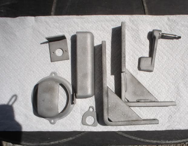
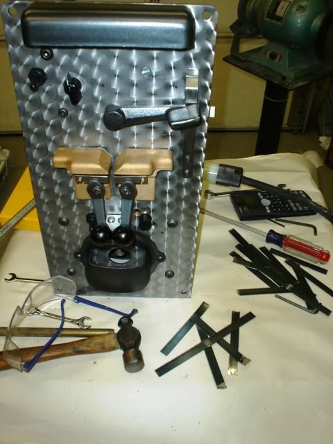
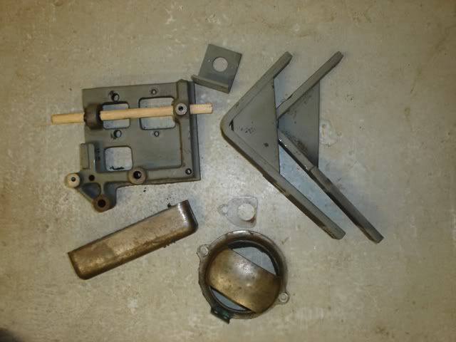
My first step was to separate all the parts to be sandblasted and get them primed and painted. Shown in the photo are the motor and transformer brackets, the lamp shade, grinder guard, and contactor bracket.
179.jpg


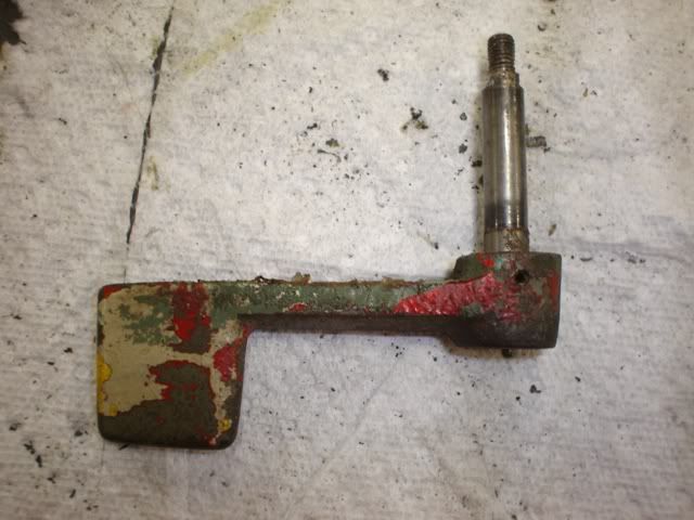
Here's the weld control handle. Can you count the different colors?

I see:

Bright Green
Dark Green
Yellow
White
Red
180.jpg


Not for long!

181.jpg


Next up, I made a trip to the local motor shop and hit the industrial supply along the way. I picked up some .018" 5-10-5 Dacron-Mylar-Dacron insulating sheet (blue), 1/16" Phenolic (tan), and 3/8" Delrin rod (white). All this is to make the old insulators shown in the left of the photo. Most of these insulators are to protect the "hot" stationary jaw from grounding to the frame.

182.jpg


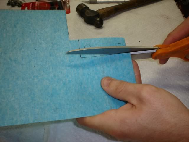
The 5-10-5 material came from the motor shop. It is used to insulate the windings of electric motors during rebuild. Thanks, Kurt, for the free "sample"!. It is tough to cut with an X-acto knife, but works readily with sharp scissors. I traced the outline of each insulator on the material and cut them out:
183.jpg


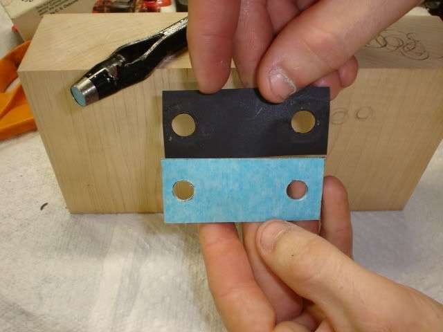
Then, I punched the necessary holes, just like if it was gasket material:
184.jpg


You'll recall that when I disassembled the welder, I damaged the cardboard insulator tubes that insulate the "hot" jaw copper bolts where they pass though the slide frame and main frame. The Delrin rod was used to make new bushings which should be more durable. I love machining Delrin, it machines beautifully and always leaves a perfect finish.

I neglected to take any photos of the machining process, but here's the finished product, next to the old bushings:

185.jpg


All the finished insulators, next to the originals:
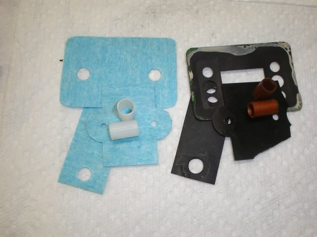
186.jpg


I intended to use the 1/16" phenolic to build a new insulating block for the weld stop contactor, but I decided the existing block was in suitable condition for re-use. Plus, my Unisaw is disassembed in a corner where I can't easily get to it. Making the new phenolic block would require sawing a number of perfectly sized squares, which is best accomplished on the table saw. Should the insulator block ever break down, it is an easy to reach part. Yes, even I have to stop *somewhere*!

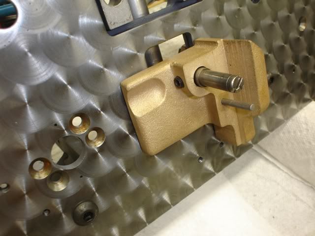
After finishing the insulators, I got to work on the welder jaws. These are machined bronze castings. Here, I'm removing the set screw that locks the clamp cam adjustment:
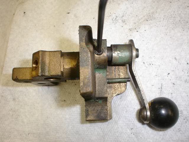
187.jpg


After sandblasting, I dressed up the back side of the movable jaw. This is important, as the two gibs ride on this surface. 600-grit sandpaper made quick work of things. Notice, the jaw was originally machined on a lathe, probably a turret lathe.
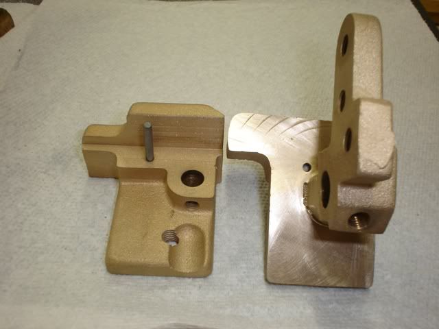
188.jpg


Then, I disassembled the grinder motor and cleaned everything up. This motor uses journal bearings and the rear journal was running dry. However, the grinder sees little use, so the bearings were still in excellent shape. Beyond cleaning, re-oiling the bearings and dressing the centrifugal starter contacts there was little to do here:
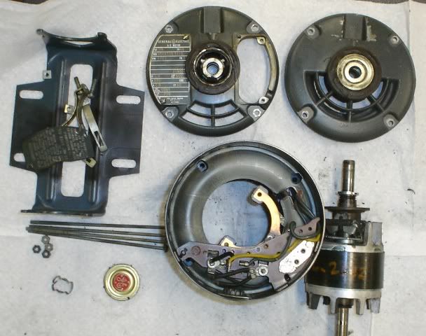
189.jpg


190.jpg


SIDENOTE: You'll recall when I first disassembled the saw, the welder was mounted on a piece of 3/8" plywood. I finally figured out why! The grinder motor is not original to the machine. The original motor is actually somewhat shorter, probably around 1/2" or more. Because the new motor is longer, the welder is actually too "deep" to fit in the cavity provided in the saw!

Good thing I haven't been able to finish-paint the machine yet... I'll have to build out the welder cavity with a custom 1/2" plate frame so that the welder will "fit".

Having just finished the motor and being in an "electrical mood", I decided to have a go at the main power contactor:
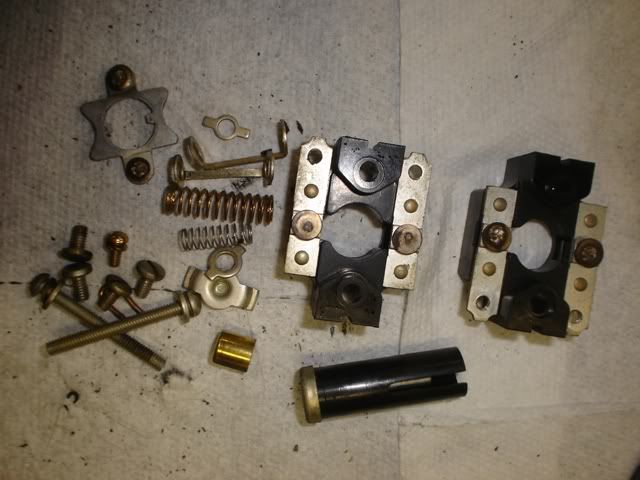
191.jpg


Again, like the grinder motor, it was in good shape. I cleaned everything up and dressed the points down and called it "good 'nuff". I couldn't quite dress out all the pitting, but I did get most of it:

192.jpg


Putting it back together took five attempts to make a video that actually made sense. Due to the miracle of television, you'll only be seeing attempt #5. :)

Fresh from futzing with the contactor rebuild, I decided to do something easy, and it doesn't get any easier than degreasing. Here's most of the hardware about ready to get a bath in degreaser:
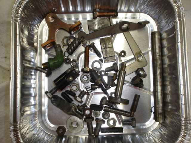
193.jpg


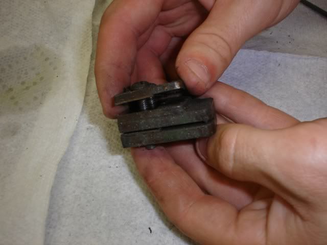
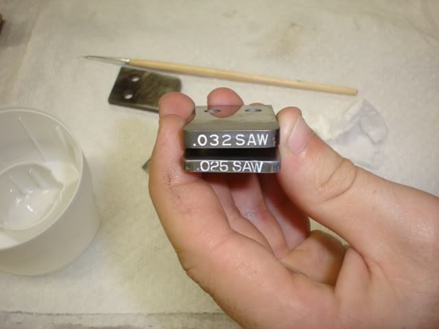
While waiting on the degreaser, I quickly cleaned up the blade thickness gauge. This gauge mounts above the grinding wheel. It's purpose is to act as a go-no-go gauge for grinding the upset weld down to thickness. Without the gauge, it would be impossible to tell if the weld was too thick to pass between the saw's guides.

The gauge is really just a couple pieces of ground tool steel, with a couple punched pieces of shim stock in-between. A little Scotch Brite cleaned things right up. Then, I used some white paint to highlight the stamped lettering:
195.jpg


194.jpg


About here, I called it a day and closed up for the night.

Day Two

The next morning, I took a trip down to the Ace Hardware store a few towns over to find new control knobs. I knew they had a rather "vintage" collection of knobs in their hardware bins. I was hoping they had something close.

For the welder width control, what I found was better than close, but an actual NOS knob from "Daka-Ware" in Chicago, IL! Unfortunately, they didn't have any spherical knobs of the appropriate size. Back at the shop, I thought about ordering a few before I remembered that Bakelite works readily with abrasives...

Here are the welder clamp knobs before:

196.jpg


I found a 1/4" by 5" bolt which I promptly threaded into the base of one of the knobs. Then, I chucked the bolt in my small lathe where I sanded down the exterior of the knob and polished it:

197.jpg


It turned out so well, I did the other one. You can't tell the difference from new!

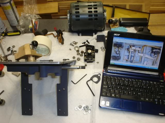
That pretty well covers cleaning up and repairing the welder's parts. While the welder transformer was drying off from it's motor cleaner bath, I took this photo of the components, ready to go back together:
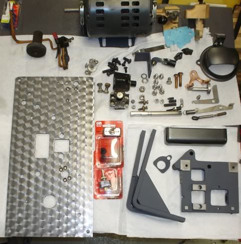
198.jpg


In addition to the new blade width control knob near the upper right, you'll also notice some new switches and switch boots in the lower left. These will replace the annealing heat control switch as well as the grinder and lamp switch. Both of the original switches were worn beyond repair.

In the next post, I'll cover putting it back together.
 
To avoid these ads, REGISTER NOW!

Dr. Bolt

Member
Joined
Jul 17, 2009
Messages
10
Location
Cullman, Alabama
I've enjoyed the thread, you're a real craftsman.
I've brought back from the dead a 18" C Monarch lathe (1947 model) and a J head Bridgeport. Not quite to the level of your saw.
I'm in the market for a Doall vertical bandsaw. "Googling" for one brought me to this thread.

Keep it up, have you restored any other machinery?
 
OP
A

A_Pmech

Well-known member
Joined
May 8, 2007
Messages
8,002
Location
IL
Dr. Bolt,

Thanks.

Cool! I didn't know this thread had made it to Google. That's neat!

The 16C is a nice machine. I'm sure you enjoy running it!

Do-All saws turn up in all kinds of strange places. Craigslist can be a good resource. "huge bandsaw" or "big metal bandsaw" or similar language is always a good sign. Hopefully, this thread will prove helpful to you as you hunt for the "right" one, as Grey Rider's website helped me with this one. :thumbup:

I've rebuilt all kinds of things, but I've never documented any rebuild to the same level of detail as this machine. After the saw is done, I have a Series II Bridgeport and an Edlund drill press fighting to be next in line. I'll probably document them the same as this saw. Back on page 3 or 4, you can see the 60's Clark forklift I partially rebuilt. Eventually, I'm going to give it a complete overhaul and replace the transmission with a hydrostatic drive system I've sketched out.

I rebuild machines to this level of detail because I enjoy the unique challenges involved. Plus, there's nothing quite like using "New" Old American Iron, back to running at peak performance.

Good luck with your bandsaw search. :beer:
 
OP
A

A_Pmech

Well-known member
Joined
May 8, 2007
Messages
8,002
Location
IL
Reassembling the Blade Welder

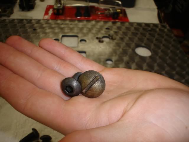
First off, I bought all-new hardware. I couldn't find truss-head screws like the originals, so I compromised and bought internal-wrenching button head screws. These will be close enough...

199.jpg


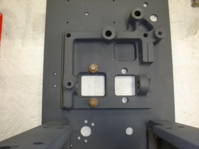
The first part to go back on is the slider frame. This bolts to the main frame with two screws and holds both the moving and stationary jaws, in addition to the weld timing mechanism. Because everything is mounted to this one piece of cast iron, no special precautions are required when putting it back on the main frame. The two bolt heads in the photo below are the movable jaw gib screws:

200.jpg


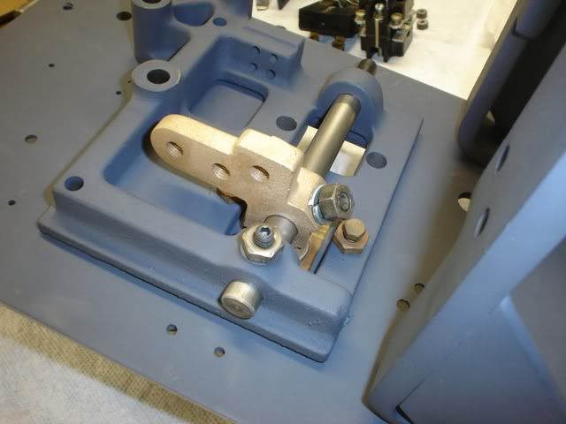
Next up, the sliding rod, movable jaw, and weld timing plunger can be installed in their proper places:

201.jpg


Here's a different view, with the transformer / motor brackets installed. They form a convenient stand which helps with the rest of the work. I, uhh, might have been a little confused as to how everything went back together. So, I read my disassembly post and looked at the photos!

202.jpg


Another angle, showing the movable jaw installed. I adjusted the gib screws until a slight drag was felt on the movable jaw, then backed off until the drag just disappeared. Then, I evened out the adjustment so the jaw was square to the front frame plate. This becomes important when the stationary jaw is installed - they must meet perfectly!

203.jpg


With the frame flipped over again, I installed the blade width adjustment mechanism as well as the actuating lever and the control lever. I debated using several different kinds of lubricant and finally settled on automatic transmission fluid. Hopefully, it will be less likely to gum up over time.

204.jpg


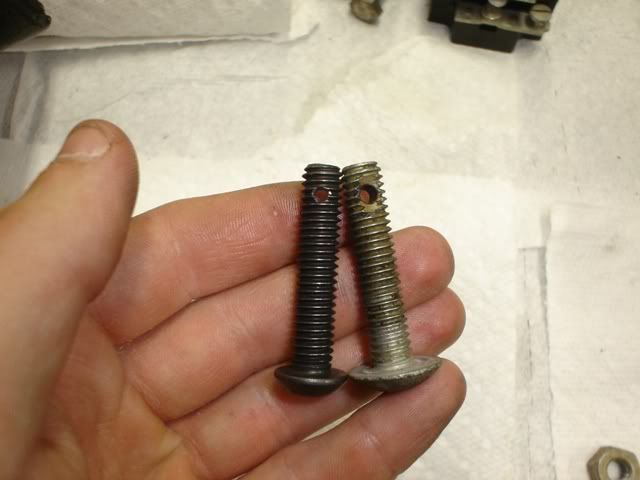
I drilled a new bolt to install the actuating lever return spring, so that it would match the rest of the hardware on the front face. I drilled an appropriately sized nut first. Then, I threaded the bolt into the nut and used the hole in the nut as a guide. It's a trick I use often when I need a cotter pin hole. Maybe on day I'll make a drilling jig from a piece of scrap...

205.jpg


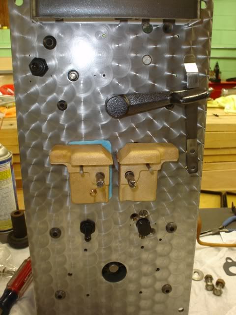
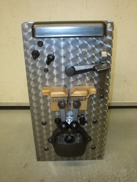
In this photo, the front is really starting to shape up. Both jaws are installed, the annealing control switch and switch boot are installed, and I was just putting in the lampholder. You can see the blue 5-10-5 behind the stationary jaw.

206.jpg


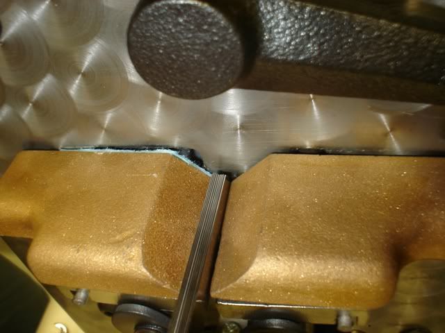
I aligned the two welder jaws using a 1/8" by 1/2" parallel. By loosening the stationary jaw screws slightly and using a brass punch, I tapped the stationary jaw into alignment with the movable jaw. When I was satisfied that everything was as close as I could get it, I torqued the stationary jaw's copper bolts.

It is important that the insulating material behind the stationary jaw be .016" +- .002. Otherwise, the stationary jaw back will not meet up with the movable jaw and will require shimming or machining to match.

After bringing the jaws into alignment, I installed the grinder motor, motor switch, annealing switch, and lamp guard. At this point, the welder was ready for wiring.

207.jpg


In the next post, I'll cover running wire and *hopefully* not letting the "Magic Smoke" out! :beer:
 
OP
A

A_Pmech

Well-known member
Joined
May 8, 2007
Messages
8,002
Location
IL
Re-Wiring the Blade Welder

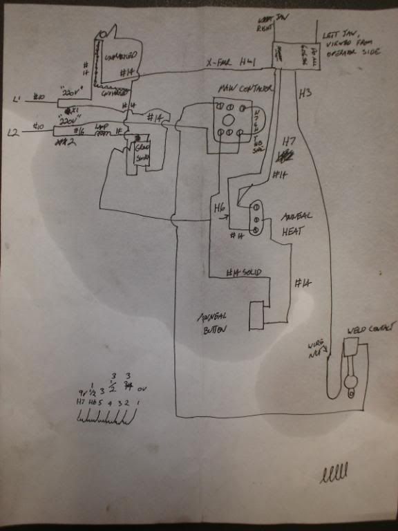
I really didn't take a lot of photos of this step, as there isn't much of interest to show. Instead, I'll focus on a couple points about the wiring of the old welder. Here is the VERY quick and VERY dirty schematic I drew up as I was cutting out all the old wire:

208.jpg


One side of the 220V lamp is wired directly to the incoming line! They did the same thing with the 220V grinder motor, using another pole of the DPST switch. "Off" really doesn't mean "Off" in either case. These problems, along with scarce 220V candelabra base bulb availability caused me to change the schematic.

Here's the "revised" version, as-built:

209a.jpg


I changed the wiring of the lamp and motor to operate on BOTH poles of the new DPST switch, in addition to installing a 50VA 220/110V control transformer to power the lamp. I could have used a 220V coil relay to switch 110V power from the saw's existing control transformer. However, the transformer option was actually cheaper due to the local availability of the part. 220VAC coil voltage relays are not a common item.

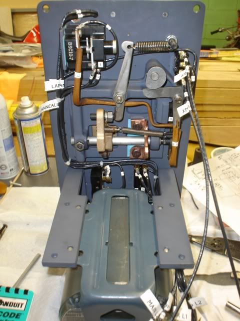
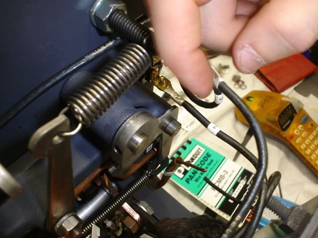
In addition to those changes, I re-wired the entire welder with #12 wire, rather than using multiple gauges. I also brought out the grinder/lamp lines and transformer lines separately, to be connected at the back of the machine. I also found a rather unusual termination of an unused transformer wire. You can just see the bare end wrapped around the other unused wires. This was not factory, I don't think. It was probably done later, by an electrician in the field, to change the welding heat setting:

211.jpg


Beyond those changes, the welder was wired as-original. Here it is, in-progress:

210.jpg


Placing wire markers:

212.jpg


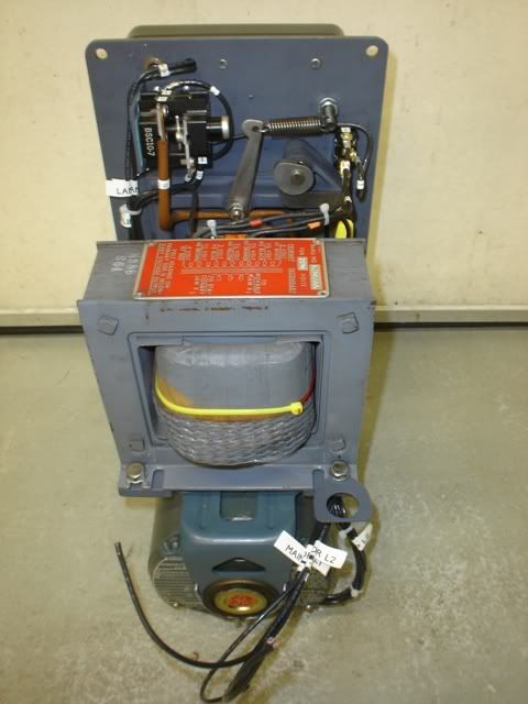
Finished:

213.jpg


214.jpg


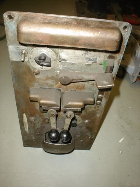
Here it is "before", just for comparison:

155.jpg


This was a short post...

In the next post, I'll cover re-calibrating the welder along with making the first welds. I'll also be providing a detailed explanation of how it actually works. So stay tuned!

I have some new videos cooking too. :beer:
 

Atlascycle

Well-known member
Joined
Aug 9, 2008
Messages
248
Location
Fremont, Ne
Build looks great. With the wire markers I would have covered the wrap markers with clear heat shrink to help them stay put. But YMMV


Jason
 
OP
A

A_Pmech

Well-known member
Joined
May 8, 2007
Messages
8,002
Location
IL
What is this little lever (circled in red) and where did it go?

Steve,

Very observant!

That little lever was originally used to lock down the annealing button for use with the Do-All "etching pencil". The etching pencil was basically a copper electrode which you could use to electrically etch, via resistance heating, whatever you wanted into the workpiece.

I have much better ways of marking parts, plus I don't have an etching pencil. Further, the little lever is annoying and gets in the way. So, I didn't rivet it back onto the frame. It will go in the "spare parts" box for the saw. I can always put it back on at a later date with a machine screw.

Atlascycle,

That's an excellent idea and very simple. In future, I'll be doing that!

Luckily, the 62-year-old markers were all intact, so I didn't have to ring out the transformer to find the correct taps. However, I have encountered machines where the markers were in a pile at the bottom of the control cabinet. With wire numbers well into the 250 range, it wasn't good!
 
OP
A

A_Pmech

Well-known member
Joined
May 8, 2007
Messages
8,002
Location
IL
Calibrating A Do-All Blade Welder

After putting the welder all back together and getting it wired I had one more step to go before I could test it. Do-All provides some guidance on how this should be done. However, they're a little vague on the specific adjustments, leaving it to the individual mechanic to figure it out on their own.

Here's a step-by-step guide:

1) Loosen all the adjustment screws, except for the cutoff rod stop screw.

2) Place a stack of feeler gauges or a gauge block equal to .147" between the two jaws. This locates the "closed" distance of the jaws.

215.jpg


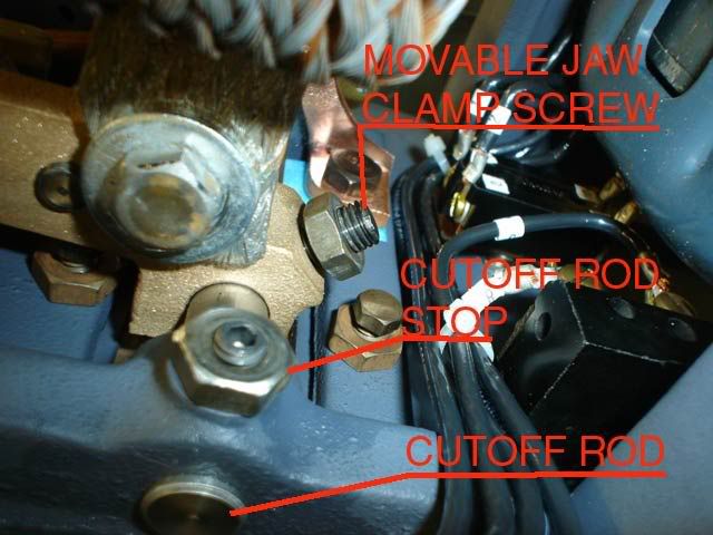
3) With the movable jaw clamp set screw loose, push the cutoff rod towards the "closed" position until it stops.

4) While holding the movable jaw tight against your feeler gauge stack, and while holding the cutoff rod against it's stop, tighten the movable jaw clamp screw. This sets the "closed" position of the jaws.

216.jpg


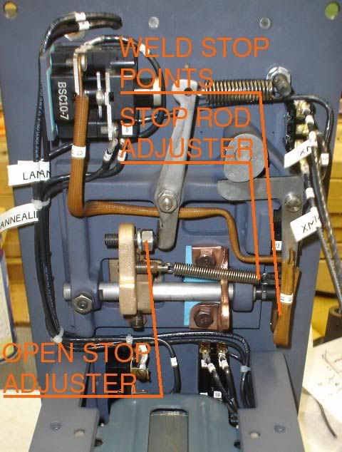
5) Now, place a stack of feeler gauges .167" wide into the jaws. Isolate the cutoff switch circuit by removing both connections (wires #13 and #14 in my new schematic.) Place the multimeter across the cutoff switch on it's diode test setting. Now, adjust the stop rod adjuster until continuity is just broken. This sets the weld cutoff timing.

6) Reconnect the cutoff switch wires.

7) Finally, place a stack of feeler gauges equal to .187" between the jaws. With the welder control lever against it's up stop on the front panel, adjust the open stop screw until it just touches the actuating lever and cinch up the jam nut. This sets the maximum open width of the jaws.

217.jpg


Make a few test welds. The weld should be a clean upset on both sides, slightly thicker to the tooth side. Once ground, it should look like this:

218.jpg


Troubleshooting

If the weld is cold or incomplete, adjust the stop rod cutoff plunger by screwing it "in" a few clicks, to increase the duration of heat.

If the blades over-run each other, the jaws are traveling too far or out of alignment. The jaw travel should be set at .040". It is also possible that you have too much tension on the blade width adjustment control.

If the weld "blows out", the jaws aren't traveling far enough, there is too much heat, or too little tension on the blade with adjustment control.

Here it is, all calibrated and ready to go:

219.jpg
 
OP
A

A_Pmech

Well-known member
Joined
May 8, 2007
Messages
8,002
Location
IL
Making A "Spacer" for the Welder

As I discovered earlier, the grinder motor is not original to the welder. The motor installed on the welder is a basic 1/4HP open frame blower motor, which works great. Unfortunately, it adds 1/2" onto the length of the welder. This explained the nasty looking plywood shim I found behind the welder during the initial disassembly back in May:

220.jpg


Obviously, I'm not going to hack off a piece of CDX to make a new shim. I considered a couple possibilities, including Nylon. I finally settled on 1/2" by 1-1/2" steel flat for the top and sides. On the bottom, 1/2" by 3" steel flat as this surface has to mount the welder support bracket.

To begin, I welded up a new band for my horizontal saw, using the blade welder. Then, I began cutting out the pieces:

221.jpg


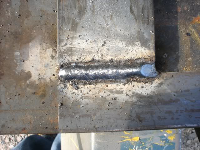
I beveled both sides of the short sections 1/8" to ensure penetration of the 6013 rod, as I intended to grind the welds smooth.

Then I squared up the pieces and clamped them to a section of 3/4" flat:

222.jpg


Here's a section after welding:

223.jpg


After grinding and flap wheeling:

224.jpg


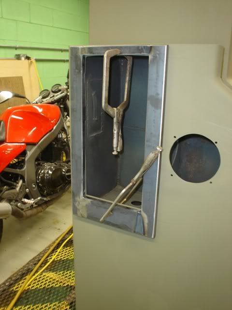
I clamped the "picture frame" to the machine and got everything into alignment. Then, I used some silver spray paint to spray though the existing mounting holes from the back side. The paint marked the location of the threaded holes that mount the welder to the machine. These locations were drilled out to a clearance hole, so the original threads in the machine would support the welder.

Separate, new holes were marked for countersunk screws to mount the picture frame to the saw.

225.jpg


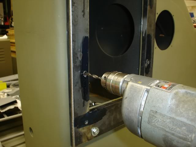
After drilling clearance holes for the welder mounting bolts, I drilled tap-drill sized holes for the new screw locations. Then, I re-mounted the frame on the saw, using bolts though the clearance holes into the threaded welder mounting holes.

Then, I used the tap-drill sized holes I drilled on the drill press earlier as drill guides, to drill tap-drill sized holes in the saw frame. Using this method ensures that all the holes will align.

226.jpg


Back at the drill press, I enlarged the tap-drill sized holes to clearance holes in the picture frame and made countersinks for the flush screws that mount the picture frame to the saw.

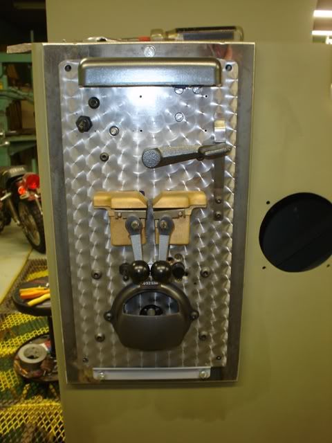
Finally, I re-mounted the picture frame for the final time, using the countersunk screws I bought for the purpose. Then, I installed the welder tip-out bracket and test-fit the welder into place:

227.jpg


Looks good!

I'm determined to paint the machine this weekend. The forecast calls for sun, low wind, and dry conditions in the lower 80's. I bought some slow reducer this afternoon.

Hopefully, my next post will be on painting this thing!

Til then... :beer:
 

fomocoforrester

Well-known member
Joined
Jun 13, 2008
Messages
3,061
Reassembling the Blade Welder

First off, I bought all-new hardware. I couldn't find truss-head screws like the originals, so I compromised and bought internal-wrenching button head screws. These will be close enough...

199.jpg


:beer:

I think they are better than "close enough"

I know it can sometimes grate a little when having to use some non original items on a restoration, especially one done to your high standard.

However, I would take satisfaction in the thought that the original designer of the machine would almost certainly have used those "internal wrenching button head screws" if they had been as readily available back in the 40's, or, indeed, if he had even known about them.

Absolutely awsome thread, by the way, especially your documentation of the whole thing.

I'm very much looking forward to your Bridgeport project. I had a look at one myself last week but the hand scraping marks had been worn completely away to within a few inches of the ends of the ways. So I am particularly interested in finding out just how worn out the machine can be and yet still be a viable restoration project.:thumbup:
 
Last edited:

KenS

Well-known member
Joined
Oct 21, 2007
Messages
726
I can hardly believe the level of craftsmanship and attention to detail I'm seeing here from someone was young as A_Pmech. And not only in the professionalism of the work, but also the level of documentation including writing, photographic, Photoshop and video skills.

I'm curious if your father instilled in you your skill set, if someone else mentored you, or if you are one of the rare breed that just comes by it naturally? Also, is the shop yours or are you working out of one owned by someone else?
 
OP
A

A_Pmech

Well-known member
Joined
May 8, 2007
Messages
8,002
Location
IL
Forrester,

Thanks! I appreciate the kind words.

I've taken to those particular screws for the time being. They have a nice "business-like" look to them. Though, I was a little upset at being unable to find proper truss heads. I'm over it though. ;)

Regarding the Bridgeport, mine shouldn't require a lot of geometry work, I don't think. The machine is a Series II, which has the wide box ways. Most of the ways look brand new, the chrome isn't even worn in. The underside of the table isn't perfect, but it's pretty close from what I've looked at. Once I get it cleaned up, I'll have to do some testing to see what the wear is and decide if I'll do any scraping.

How worn is too worn depends largely on how much time you want to spend and how much learning you want to do. Rebuilding the slide-way geometry is not for the faint of heart. But, approached carefully and methodically, it can be done with the simplest of tools. A scraper, surface plate, blue, and a 4' master straightedge and a 3' master square are all you need for most projects. Connelly's book "Machine Tool Reconditioning" is THE book on the subject of geometric rebuilding.

Personally speaking, with the glut of manual machines on the market I wouldn't waste my time with a machine in need of geometry work. Spindles or mechanical, fine. That's easy work. But scraping takes a lot of patience and a TON of elbow grease. It does give you an appreciation for precision, however.

Ken,

Thanks! I'm getting there. :thumbup:

A little bit of all of the above is about the only way I can describe it. However, if it came "naturally", I wouldn't have to work so hard to get good at it! I'm just very driven.

I was home-schooled from an early age, so I could discover where my interests lie and follow them. My parents did everything in their power to provide me with a very wide range of opportunities. I did my best to take advantage of those opportunities as they came. :beer:

Dad and I built the shop over a 7-year period as time permitted. The design is mine, as is everything in it. :beer:
 
Last edited:
OP
A

A_Pmech

Well-known member
Joined
May 8, 2007
Messages
8,002
Location
IL
Too tired to post as usual tonight, but here are a few photos:

228.jpg


229.jpg
 

Bolster

Well-known member
Joined
Jul 8, 2008
Messages
4,056
Location
Mexifornia
The current incarnation of this machine is the Do-All 3613-1 The only thing the 3613-1 offers over my V-36 is a higher band speed, 5,200 FPM versus 1,600 FPM. A VFD and input pulley change can fix this, should I decide it's worthwhile.

AP, I have a question from the first page...why did D-A up the band speed (significantly!) in their current production saws? Isn't the slower FPM an advantage for metal sawing? :headscrat
 

porschedude996TT

Well-known member
Joined
Oct 28, 2007
Messages
2,384
Location
Santa Maria, California
To avoid these ads, REGISTER NOW!
OP
A

A_Pmech

Well-known member
Joined
May 8, 2007
Messages
8,002
Location
IL
Porsche,

Yes, there are. Not nearly as many as in many other manual machines though, especially heavy engine lathes. I recall counting over 120 gears inside the headstock of my lathe, each one shaped, ground, and lapped into it's mate before being installed in the machine. It has a 27 geared speeds on four shifters, so there's a lot going on in there.

The lathe also has four oil pressure pumps, this biggest of which is the 1/2 HP main lubricating and hydraulic pump. Production-patter mills also have a lot of stuff moving in them, such as Old Car Guy's K&T 2D Rotary. Back before computers, keeping leadscrews and feeds in time was done entirely by large trains of gears and lots of shafting. Large machines have a nice sound to them.

Bolster,

You're correct. Most metal sawing is done below about 650 FPM with standard carbon steel bands. Aluminum is in the 500-2,500 range depending on application, mild steels in the 350 range, alloy steels 200-300, high alloy steels and tool steels 75-150, titanium, stainless and other tough metals 50-100. For bi-metal bands, the speeds are about 20% higher.

However, with carbide-tipped bands, a relatively recent invention, sawing speeds can be MUCH higher as Steve said. There's a video on Youtube which I can't find right now showing production de-gating of aluminum castings with a 1" carbide-tipped band at around 5,000FPM + as I recall. VERY impressive.

Wood is usually sawn around 2,000 to 9,000 FPM depending on species, application, etc. Foam, cardboard, leather, cloth, etc. are all sawn at high band speeds with special razor-edge bands. These are the materials Do-All probably had in mind when they increased the band speed range of their machines.

It is also possible to buy a Do-All saw with a three-speed transmission, and a 15 HP motor, which increases the range to 0-10,000 FPM (that's 113 MPH!) for friction sawing. With enough horsepower, a friction saw can go though tool steel faster than a plasma cutter and leave a much better kerf. It is not very enjoyable work.
 
Last edited:
OP
A

A_Pmech

Well-known member
Joined
May 8, 2007
Messages
8,002
Location
IL
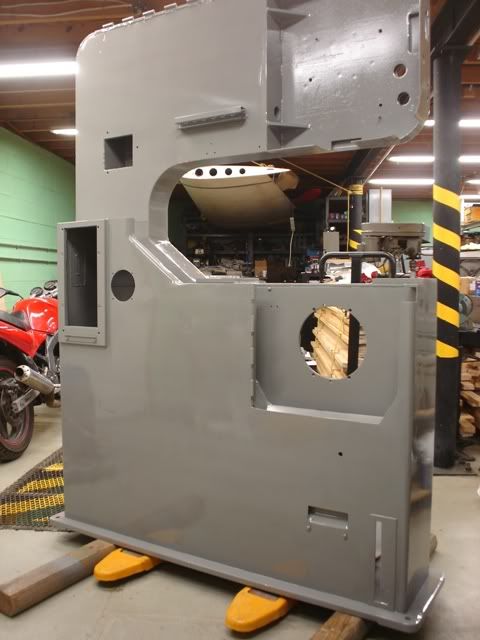
Painting the Machine

This weekend, the temperature, humidity, wind and my time finally came together. Friday evening, I prepped the parts and tacked everything off in preparation for painting. My original intention was to paint the small pieces Saturday and the large pieces Sunday.

Friday night, I rode down to TSC and bought a new HVLP spray gun. This is my second HVLP. I have the pint-sized version of this gun and found it to be a most excellent spray gun for the price. With that in mind, I bought the last one of these TSC had.

Saturday morning, I spot-primed a few areas where I did some filling and touch-up work, including around the "picture frame" shim that mounts the blade welder.

238.jpg


A cold front was slow in passing and by 10 am Saturday morning the wind was blowing 14MPH and gusting as high as 18 MPH. NOT good weather for spraying a finish coat. So, I packed up and called it a day.

Sunday morning broke cool, dry, and still. I quickly rolled out my tarps, moved out the saw main frame and the large parts and hung the small parts.

The paint in use is NAPA brand urethane enamel, 55-51060 00(A).

234.jpg


I inter-mixed the two quarts of paint I had, to ensure a color match between quarts.

235.jpg


Then, I reduced for 75-85F.

236.jpg


And catalyzed.

237.jpg


Pot life for this paint is four hours. Because it's a urethane, it is very slow to cure. Time to dust-free is 80 minutes, and the paint continues to flow for about 24 hours.

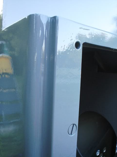
I found this paint difficult to spray. Unlike an automotive enamel, it is much more viscous. Nothing like a brushable enamel, but thick enough that it didn't atomize as an automotive paint normally does. As a consequence, I had to alter my application technique to obtain a smooth finish. I found the best way to spray this paint was HEAVY. Angling the gun about 45 degrees into the direction of spray and spraying just shy of sags proved to be what the paint wanted. This is an unconventional technique, but I've found it does provide good results with heavy-bodied urethanes.

After reducing and catalyzing, I had about 3/4 of a gallon of paint to work with. I ended up using all but 4oz. of it.

233.jpg


About half an hour after spraying:

231.jpg


Going back inside:

232.jpg


The frame, inside for the night:

228.jpg


One of the castings for the trunnion:

240.jpg


This morning, dad did a little wet sanding and buffing to de-nib a few of the parts. Here's the result, with the door back on:

239.jpg


230.jpg
 

KenS

Well-known member
Joined
Oct 21, 2007
Messages
726
A_Pmech,

I know it's a pain, but any way you can upload your photos to the GJ server rather than linking to PhotoBucket?
 
OP
A

A_Pmech

Well-known member
Joined
May 8, 2007
Messages
8,002
Location
IL
Grrr!

I knew this was coming eventually.

A_Pmech,

I know it's a pain, but any way you can upload your photos to the GJ server rather than linking to PhotoBucket?

Ken,

Not sure...

I have about 240 640x480 photos so far! I'm not sure if Ryan would appreciate all that bandwidth. Maybe I should ask?

FWIW, the photos are showing up OK for me at the moment. Maybe because they're already cached?


Elroy,

Might have to do that, I'll check into that too.

:beer:
 
OP
A

A_Pmech

Well-known member
Joined
May 8, 2007
Messages
8,002
Location
IL
I just noticed if you right click and choose "open image in new window"; I can see the pics!

:lol_hitti :beer:

It looks like my Photobucket account resets this Wednesday. I'm going to research a couple of possible options...
 
OP
A

A_Pmech

Well-known member
Joined
May 8, 2007
Messages
8,002
Location
IL
OK, just upgraded to Photobucket Pro. Supposed to be unlimited bandwidth and a whole bunch of storage.

If the photos give you guys any problems, let me know so I can pound on Photobucket and get my money's worth. :)
 

KenS

Well-known member
Joined
Oct 21, 2007
Messages
726
Grrr!

I knew this was coming eventually.

Ken,

Not sure...

I have about 240 640x480 photos so far! I'm not sure if Ryan would appreciate all that bandwidth. Maybe I should ask?

Washing a 640x480 image through Photoshop's "Save for Web" option with output set to JPEG Medium creates a very clean 40k image x 200 = about 8mbs of storage here for all your photos in this thread. Considering a flash drive can hold 8 gigs or more, 8 megs is a fly speck.

I don't know about others here, but this happens to be one of my favorite threads in GJ and I think-- to use a newspaper term-- it will remain "evergreen." In fact I would make it a sticky, but that's for someone else to decide.

The problem is that the day you shut down your PhotoBucket account is the day this thread becomes relatively valueless since the progress photos are an integral part of your project documentation.

Maybe the moderators here can weigh in on bandwidth considerations, but I don't know how many times both here and on other sites the information has become worthless because of long-broken links.

For instance, almost everyday someone here will post a craigslist link to an item that will go dead in a month or so. That leaves the scattered detritus of worthless posts and wasted bandwidth clogging many of the forums. And often times the title of the thread gives no hint that the poster is pointing to a craigslist link.

If bandwidth is a serious consideration, I'd much rather see those links cleared out and your valuable information preserved for posterity.
 
OP
A

A_Pmech

Well-known member
Joined
May 8, 2007
Messages
8,002
Location
IL
Ken,

Wow, a sticky nomination! That's never happened to me before.

You're right on all counts about losing the documentation. Though, I've had my photobucket account since they first started and so far I don't think I've lost anything. I upgraded to Photobucket Pro, as a temporary solution to the bandwidth problem.

Once this thread is complete, I suspect I'll have somewhere around 400-500 photos in total. At that point, I'll see about archiving them in some way, just in case Photobucket kicks the bucket. I'll send Ryan an IM on the subject and see what his input is.

Porsche, Billymade,

Thanks. It does have some "mottling" (low-frequency orangepeel) mainly due to the viscosity of the paint. It was never meant to give a "show finish". However, a quick go-over with 1500 followed by buffing and glaze sure does give it something pretty close to a show finish on the top door.

I'm not sure if I want to wet-sand the entire machine though. This is, after all, a machine for my shop. It will get dinged, chipped, etc. from day one. I don't want to be afraid to use it. :)
 
OP
A

A_Pmech

Well-known member
Joined
May 8, 2007
Messages
8,002
Location
IL
Stang,

Interesting...

That appears to be the later and lighter version of the V-36, the 3613-?. Judging by the control layout and speed indicator, it could be anywhere from mid 70's and newer, I think.

I'd like to hear the story behind the missing table! They're not exactly easy to remove or hard to misplace. (I'm going to guess somebody tried lifting the machine from under the table and broke something.) One and a half tons hanging by the table trunnion doesn't work too well...

A new table from Do-All would run every bit of the $3,000 asking price.
 

kidatari

Well-known member
Joined
Jan 14, 2007
Messages
104
Location
So. NH
Absolutely fantastic attention to detail. Thanks for putting all the hard work into documenting the process for the rest of us to enjoy. I have learned a ton from the tips and tricks that you've provided.

Thanks again for documenting the process. Now all I need to do is find a Do-All of my own ;)
 

bimmer1980

Well-known member
Joined
Feb 5, 2009
Messages
2,105
Location
York, PA
I'll nominate this as well for a sticky!

Very impressive work! I would imagine the skills, attention to detail and preciseness comes from the aviation background.... Am I right to assume that you have your A & P?

Aircraft equipment has little room for error, so it is either built complete to spec or scrapped. It's nice to see the same attitude applied to this machine. I was surprised at the good condition of the machine when you started on it. I know many people, myself included, would have been tempted to run the machine as is. However, the little issues that are resolved and fixed so the machine runs like a top are what makes machining and projects fun. Fighting a machine is frustrating......

This will be great to see this machine in operation!
 
To avoid these ads, REGISTER NOW!
Top Bottom