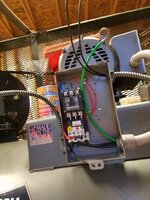
Can anyone verify if this is the correct wiring for the motor starter , circle on the left says low oil switch , on the right of box is pressure switch , thanks
Sent from my SM-G930V using Tapatalk
The diagram needs to be changed around. Also, the control wiring on the diagram doesnt match the actual wiring you have. (more on this below).
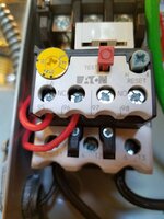
As pointed out by matt_i, your solid state overload will most likely almost instantaneously trip as there is no current going through the T2 coil and it will see that as a phase loss.
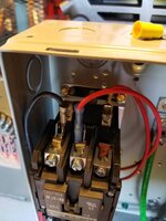
Incoming supply line 2 needs to go to L2. You can use the 3 phase starter(as long as its rated for the 10HP in single phase- more below) but you will need to run a #6 THWN from T2 to L3 to prevent the phase loss tripping. Motor connects to T1 and T3 as on your diagram.
Control wiring needs to be adjusted.
You can leave the overload relay hooked up to L2 and A2 for the coil(i cant tell if its hooked up to L3 or A2).
The black lead from the pressure switch (or low oil switch) can connect to low oil switch (or pressure switch) and then on to A1 for the coil.
Make sure the other end of that is connected to L1.
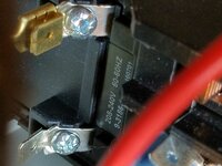
In regards to HP rating on the starter, do you see any ratings?
If not how about model numbers?
Starters have lower HP ratings when used on single phase. You definitely want to make sure its rated for that beast.
It seems like there could be a problem here. Part of the control wiring appears to be landed on L2.
In addition, a 3 pole starter and overload section is going to give you phase loss very fast and very consistently, when used on 1 phase. Two options are either to connect T1 to L2 and then L2/L3 to the motor, or eliminate the normally closed (NC) contact from the control circuit and run without the overload protection.
Control wiring can stay on L2 if wired as i pointed out above.
I Typically see manu. wire T2 to L3.
I would NOT run without overload protection...


 I missed the low oil switch. Good idea on the control fuse also.