
I have a 3 way switch set up in my stairway it currently works only with one switch. Meaning the switched need to be in a certain direction each for it to work. I can walk up my stairs and turn the switch on then go upstairs and shut it off and that works. Now if someone else tries to come upstairs and flips the switch from the bottom it will not work and when I go to come back down the stairs and flip it from up top the light also will not go on either. It's driving me nuts so I tried to figure it out today found some online diagrams but none really showed my situation.
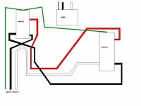
I drew up a diagram maybe someone on here can figure it out and help me a bit.
I know the power source but cant figure out how the light is getting fed its wires?
Please take a peek and let me know what you think
Thanks
I drew up a diagram maybe someone on here can figure it out and help me a bit.
I know the power source but cant figure out how the light is getting fed its wires?
Please take a peek and let me know what you think
Thanks


") , the one you posted?
, the one you posted?
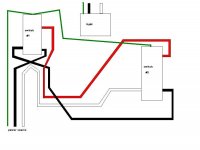
 I think switching those two wires will solve your problem, unless you gave us some bad info, lol.
 Does it not? Apparently your vision is being effected by too much bingo? I'm trying to figure out his (tstang90's) wiring problem, NOT troubleshooting a properly wired circuit. Never claimed a junction box is needed.