To avoid these ads, REGISTER NOW!

VISE REPAIR 101 all vise repairs, lubricants, sources for parts and the tricks to fix

MattGavriloff

Well-known member
Joined
Jan 3, 2021
Messages
290
Location
Escanaba, Mi. South of Canada...
PIERCE is correct, I am "mid repair" on a very similar situation. Problem is I'm also "mid too many other things" to devote the time I'd like to that project, or this post...lol

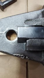
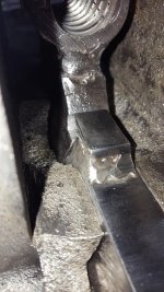
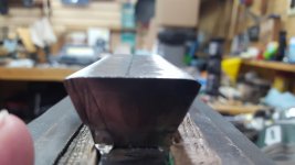
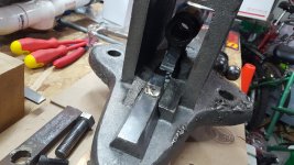
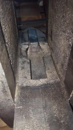
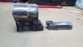
The quick and dirty is I have currently filed/ground/sanded the retaining block to fit, you can see the initial fit, and then where they will be once it's done. The retainer is not "tight" to the nut, there's a bit of wiggle (1/16" or so). Reason being my screw isn't perfectly straight so we've decide it's probably unwise to have the nut completely rigid.

Next steps are, finish my thread repair because I still haven't gotten to that, finish fitting the screw to the nut (The bend in the screw is requiring some...massaging), and then fit the outside of the nut, and the inside of the slide together. I asked PIERCE to add the additional tube on the outside, for as much additional strength as possible, knowing I'd have to take some areas of it down potentially half again as thick. I'd rather have to remove now, then wish we had added more thickness later if it broke. I'm happy with how strong it looks, and the thread alignment inside is amazing!

I really want this big girl back in action, even if only for my own amusement, but it's still going to take some time...I knew this, I'm just impatient...lol

And again, I want to thank PIERCE for donating his time and skill to my frivolous project. I certainly do not need a 6 1/4" vise, but his willingness to help shows he understands the pleasure of resurrecting a big old tool.

That's all I got for now, I've gotta get some sleep tonight or I'll never make it through tomorrow...lol
 

Attachments

  • 20210304_192056.jpg
    20210304_192056.jpg
    115.8 KB · Views: 35
  • 20210305_201926.jpg
    20210305_201926.jpg
    81.2 KB · Views: 30
  • 20210305_201840.jpg
    20210305_201840.jpg
    98.9 KB · Views: 32
  • 20210305_201824.jpg
    20210305_201824.jpg
    83.7 KB · Views: 31
  • 20210305_183730.jpg
    20210305_183730.jpg
    84 KB · Views: 31
  • 20210304_222022.jpg
    20210304_222022.jpg
    55.3 KB · Views: 31
  • 20210304_192541.jpg
    20210304_192541.jpg
    152.7 KB · Views: 34
To avoid these ads, REGISTER NOW!

MattGavriloff

Well-known member
Joined
Jan 3, 2021
Messages
290
Location
Escanaba, Mi. South of Canada...
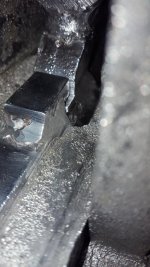
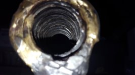
Last couple pics showing the BEAUTIFUL alignment of the threads inside the nut, again props to PIERCE! First focused close, then on the deeper threads. The crack is darker, but can hardly be felt in spots with a pick.

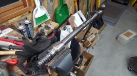
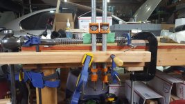
And this is far as my screw goes currently. I hadn't detected the bend here initially. I knew it wasn't straight at the weld. This bend makes a "high spot" about 6 inches from the end. It is NOT an issue inside the nut, or with PIERCEs work, just fyi...lol. I just missed it when inspecting/cleaning the screw. And with the nut initially broken, I couldn't "feel" it. This screw and nut are on their last go round anyways, so if I can't ever so slightly straighten it, I'm going to gently file/sand the high spots till she fits. It's tight enough before the sticking point where I'm not at all worried about loosening it up a bit.

EDIT: second picture with the ruler makes the bend look worse than it is, the ruler is cocked left a bit. In the first of those two pictures you can see the 'dip" on the opposite side. Just the highest points in the middle and on the ends of that "arc" will be adjusted.

Last picture should show the problem we were solving for BK if he didn't go back far enough to find it.

Cheers and night all...:beer:
 

Attachments

  • 20210304_222124.jpg
    20210304_222124.jpg
    105 KB · Views: 30
  • 20210305_184217.jpg
    20210305_184217.jpg
    135 KB · Views: 32
  • 20210305_184201.jpg
    20210305_184201.jpg
    147.2 KB · Views: 31
  • 20210304_194621.jpg
    20210304_194621.jpg
    150.6 KB · Views: 31
  • 20210304_192134.jpg
    20210304_192134.jpg
    80.9 KB · Views: 28
  • 20210304_192153.jpg
    20210304_192153.jpg
    108.3 KB · Views: 32
Last edited:

PierceA

Well-known member
Joined
Aug 6, 2020
Messages
471
Location
SE Michigan
Matt: do you have a hydraulic arbor press at work? If so, using that press will be the safest way to straighten your mainscrew.

You can follow the same method I showed for straightening the handle on the Parker 953 'Fluff-Up' thread.

If I had your mainscrew here, I'd have it straight in less than 30 minutes. [I've straightened a lot of bent handles and more than a few main screws]..

What ever you do do not try using a hammer or sledge hammer to straighten it. any impacts can damage the threads. If the threads are protected with a hunk of wood, the control of how much the screw is straightened or possibly become over bent is difficult to control..

Some form of a controllable displacement press is needed for this job.

It is very good news that the threads of the nut came out as snug and properly aligned as they did. It's a gamble to repair a split nut without the mainscrew to use to size and check the fit in the nut.. Thankfully the repair came out well.

PierceA
 

MattGavriloff

Well-known member
Joined
Jan 3, 2021
Messages
290
Location
Escanaba, Mi. South of Canada...
DRIVES, yes they returned the other day. The pictures I've posted during fitment have all be since they arrived...:bounce:

PIERCE, yes we have a press at work, and today I'll see about getting access this week sometime. The repair side of the shop won't likely be open to day (no appointments).

I also envision a jig with pipe clamps and my ball joint press C-clamp. So I may try to rig something up this weekend at home. Don't worry, at no point will hammers be involved in fitting or straightening :thumbup:
 
OP
D

drivesitfar

Well-known member
Joined
Oct 23, 2013
Messages
36,114
Location
Pacific Northwest
Matt: I knew your vise nut arrived and you must not have used USPS or maybe they decided to go back to work again cause that was fast.

here's some LUCK, but with Pierce in your corner you really only seem to need more time to finish it cause its looking good so far.

warming up yet or still snow on the ground?
 

Shiftless

Well-known member
Joined
Mar 9, 2014
Messages
14,692
Location
East Bay SFO
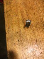
I decided to do something with this Reed 103 that I’ve had for a few years.

I bought it cheap for parts. Missing a handle and had a big chunk broken out of the tail end of the slide.

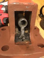
A while back there was a fellow GJ member who needed the main nut. To remove the nut I tried to pound out the pin but like most of them, it was stuck. I cut it off with a Dremel cutting disc. He changed his mind about buying the nut so I put the vise back on the shelf.

Fast forward to March 2021. I changed my mind about parting this one out. So I needed to replace that locating pin. Soak in penetrating oil, hammer and punch, repeat. Bottom up, top down... Nothing budged.

I decided to drill.
Here are the results of a 1/8 inch hole in a 1/4 inch pin.
Even with the extensive drilling I still needed a punch and a 3 pound hammer to drive it out.

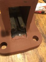
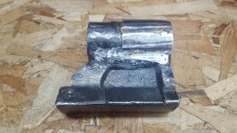
Before and after pics of cleaning the slide. Shown are the results of 4 minutes (I timed it!) with a 3 inch drill mounted blue Nyalox wheel. Scrubbing with Scotchbrite and mineral spirits would have resulted in an even cleaner result. I wanted some blackness to remain. So I sprayed on a bit of Fluid Film and wiped the surfaces with a paper towel. The final result of this treatment is shown in the 4th photo. (Too bad about the chip :()

This one is getting painted. It’s now in primer. (Seen in the first 2 photos)
 

Attachments

  • 74C1AF4E-A6C5-490A-9F1C-A04BFFA4E3B0.jpg
    74C1AF4E-A6C5-490A-9F1C-A04BFFA4E3B0.jpg
    97 KB · Views: 40
  • BBDA5B80-2A19-41A7-8497-F6411B323377.jpg
    BBDA5B80-2A19-41A7-8497-F6411B323377.jpg
    84 KB · Views: 39
  • BF87A140-D391-4705-B07F-85D918F9C164.jpg
    BF87A140-D391-4705-B07F-85D918F9C164.jpg
    81.8 KB · Views: 38
  • A349D62C-B8F6-4C33-B090-9CC1C58BF3C4.jpg
    A349D62C-B8F6-4C33-B090-9CC1C58BF3C4.jpg
    154.3 KB · Views: 44
  • D2EC648E-9336-4A63-A230-AAAFCCB8FE94.jpg
    D2EC648E-9336-4A63-A230-AAAFCCB8FE94.jpg
    135.5 KB · Views: 40
  • 7BBB903C-6E55-45B7-9A2E-D245D77626CE.jpg
    7BBB903C-6E55-45B7-9A2E-D245D77626CE.jpg
    118.5 KB · Views: 37
Last edited:
OP
D

drivesitfar

Well-known member
Joined
Oct 23, 2013
Messages
36,114
Location
Pacific Northwest
Shift: nice work!! even though that chip on the bottom of the back of your slide is a bit more than a BEAUTY MARK it looks like it's still covering the screw and gives you full access to opening it widest. the jaws look great too.

now about hat handle? maybe an old wrench that has a point on itf (sorry I forgot what those iron worker's wrenches are/were called at the minute, but I own a few) shined up and pinned in place to give it a better look on the shelf?
 

Shiftless

Well-known member
Joined
Mar 9, 2014
Messages
14,692
Location
East Bay SFO
Thanks Drives and Fretters.
It’s shaping up such that I’m now glad that I didn’t sell off the vise nut, even though the agreed price for just the nut was triple what I paid for the whole vise.
 

MattGavriloff

Well-known member
Joined
Jan 3, 2021
Messages
290
Location
Escanaba, Mi. South of Canada...
Wow, SHIFT, that was one stuck pin! Makes me a little apprehensive about working on any of my Reeds. I had a heck of a time with the pin on a Parker 104 I'm currently stripping, but it came out before I reached for the drill...lol.
 

PierceA

Well-known member
Joined
Aug 6, 2020
Messages
471
Location
SE Michigan
Hey Matt. that is a fairly noticeable amount of bend in the last 5-7" of the mainscrew..
Good news that you have an arbor press at work.

A stout workbench edge to put the screw on, sitting on two riser blocks, then a heavy clamp in between the two riser blocks, with a v-block or wood block on the high spot of the bend, Then you can make the screw straight, then back off, and note how much the screw springs back. then take note of the amount of springback and next press the screw past straight plus about 1/2 or 3/4 of the amount of spring back..
The screw should spring back to nearly straight. Depending on the strength of the mainscrew steel, it may require pressing more past straight than I mention above..

Hope to see the vise together again soon!

PierceA'
 

ChefRex

Well-known member
Joined
Jun 1, 2020
Messages
3,798
Location
NJ
Last couple pics showing the BEAUTIFUL alignment of the threads inside the nut, again props to PIERCE! First focused close, then on the deeper threads. The crack is darker, but can hardly be felt in spots with a pick.

And this is far as my screw goes currently. I hadn't detected the bend here initially. I knew it wasn't straight at the weld. This bend makes a "high spot" about 6 inches from the end. It is NOT an issue inside the nut, or with PIERCEs work, just fyi...lol. I just missed it when inspecting/cleaning the screw. And with the nut initially broken, I couldn't "feel" it. This screw and nut are on their last go round anyways, so if I can't ever so slightly straighten it, I'm going to gently file/sand the high spots till she fits. It's tight enough before the sticking point where I'm not at all worried about loosening it up a bit.

EDIT: second picture with the ruler makes the bend look worse than it is, the ruler is cocked left a bit. In the first of those two pictures you can see the 'dip" on the opposite side. Just the highest points in the middle and on the ends of that "arc" will be adjusted.

Last picture should show the problem we were solving for BK if he didn't go back far enough to find it.

Cheers and night all...:beer:
That mainscrew nut is so ugly that it is beautiful! Nice work Pierce!
 

PierceA

Well-known member
Joined
Aug 6, 2020
Messages
471
Location
SE Michigan
Shiftless: how long is that Reed 103 without the mainscrew ? Would it fit into a USPS large flat rate box?
Do you have another parts-vise with an intact rear corner on the slide? We could work out something for me welding a new corner onto the slide. ?

PierceA
 

PierceA

Well-known member
Joined
Aug 6, 2020
Messages
471
Location
SE Michigan
ChefRex: yeah, it's pretty hard to do all that needed to be done on that poor abused nut without some scars and lumps and bumps remaining.
I asked about just improving the welds on the steel nut on the cracks. But Matt and I decided that since the nut was hidden inside the vise that 'ugly' wasn't a problem.. BUT strength of the nut sometime in the future might be.. So I went ahead and fit a steel sleeve over the welded nut.. And sweat-brazed it over the nut..
If you think it's a bit homely now, you should have seen it with the torch-blacked metal and globs of flux and wild bumps and excess brass.
I ground and polished the exterior to try to 'put perfume on the pig'.

BUT internally it is amazing how good it came out. Like Matt said, you can look hard for the old crack and in some spots it's virtually invisible. And at worst it's a thin dark line.. And trying to feel the intersection of the crack is almost impossible..

And when Matt threaded his mainscrew into the repaired nut, he said it was like threading two new items together..
Hopefully straightening the mainscrew will get the two parts working together again..

I'm sure Matt is anxious to get it reassembled, and working as well..

PierceA
 

Shiftless

Well-known member
Joined
Mar 9, 2014
Messages
14,692
Location
East Bay SFO
Shiftless: how long is that Reed 103 without the mainscrew ? Would it fit into a USPS large flat rate box?
Do you have another parts-vise with an intact rear corner on the slide? We could work out something for me welding a new corner onto the slide. ?

PierceA

That’s a very generous offer, PierceA! Thanks!
Unfortunately, I don’t have a parts vise right now to donate a chunk of iron. For now, I’ll just make it look great and function as well as it can without a handle.

edit:
I’m going to order some supplies from McMaster Carr and build my own handle from a 1144 steel rod and a pair of stainless steel shaft collars. I’ll take a picture of the final product some time next week. Amateurish, but quick and inexpensive for a guy with no lathe or oxy acetylene torch.


.
 
Last edited:

Fretters

Well-known member
Joined
Jan 25, 2014
Messages
4,217
Location
South Yorkshire, England
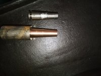
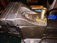
For some unknown reason, I felt the urge to start making a new taper pin from brass/bronze for the swivel jaw. :D Taper's sorted, but can't decide what to do for the head/top.
 

Attachments

  • IMG_20210307_131822Z.jpg
    IMG_20210307_131822Z.jpg
    150 KB · Views: 33

Shiftless

Well-known member
Joined
Mar 9, 2014
Messages
14,692
Location
East Bay SFO
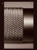
For some unknown reason, I felt the urge to start making a new taper pin from brass/bronze for the swivel jaw. :D Taper's sorted, but can't decide what to do for the head/top.

How about knurling?
 

Attachments

  • 6C15CCAD-CE40-422C-A2D3-16A568BE28B4.jpg
    6C15CCAD-CE40-422C-A2D3-16A568BE28B4.jpg
    90.2 KB · Views: 15

Shiftless

Well-known member
Joined
Mar 9, 2014
Messages
14,692
Location
East Bay SFO
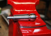
Do you think you could turn a shape like this on your lathe?
 

Attachments

  • 09CBB9E1-51FC-4286-BEAE-E56DACB0F587.jpeg
    09CBB9E1-51FC-4286-BEAE-E56DACB0F587.jpeg
    23.2 KB · Views: 12
To avoid these ads, REGISTER NOW!

KMScott

Well-known member
Joined
Feb 14, 2012
Messages
4,650
Location
Daufuskie Island, South Carolina
Did consider knurling, but it's not floating my boat, on this occasion.Trying to think of something unusual, different etc., but not something which'll take forever to achieve either.

I did one like this. Bronze is a great material to make pins out of. I like using 300 series SS so it would not rust but would have used Bronze if I had some.
 

Attachments

  • Prentiss 21 Restored-8-2017 (1).jpg
    Prentiss 21 Restored-8-2017 (1).jpg
    112 KB · Views: 30

steaks&anvils

Well-known member
Joined
Oct 15, 2016
Messages
2,470
Location
Colorado
How about knurling?

Did consider knurling, but it's not floating my boat, on this occasion.Trying to think of something unusual, different etc., but not something which'll take forever to achieve either.

Fretters, knurling rules! Knurl on dude!

Cruise this thread for some prime ideas:

https://www.garagejournal.com/forum/showthread.php?t=415933

But, if it isn't what you want for this "vice", try looking at wine bottle stoppers.:lol_hitti:beer:
 

Outlawmws

Well-known member
Joined
Aug 9, 2011
Messages
39,419
Location
The Badlands
Frett - Best is to have a SHORT taper on the opposite side. so when its out, you reverse it and store it in the top half hole..

For between the two tapers maybe a series of 3 "U" grooves for grip? This is a common treatment for revolver ejector rods
 
OP
D

drivesitfar

Well-known member
Joined
Oct 23, 2013
Messages
36,114
Location
Pacific Northwest
FRETTERS: I do like a brass piece shined up and if you maybe want to practice your skills maybe carve out the PROTO gal who's head would fit in nicely when your swivel jaw is in use.
 

Attachments

  • proto logo 004.jpg
    proto logo 004.jpg
    101.9 KB · Views: 25

Fretters

Well-known member
Joined
Jan 25, 2014
Messages
4,217
Location
South Yorkshire, England
Cheers chaps. :) Plenty of ideas for me to mull over, & gain inspiration from now.

Whilst on the subject of swivel jaws, some questions. The taper I've copied from the original pin is fractionally off with regard to the internal taper, (which shows that what I thought may have been slight wear on the original pin may not be, so I'm going to play around with the angle to try & get a better fit), but that did start me wondering.

How tight are the tolerances on the swivel jaws you have across there? Any slight play between the jaw & body, & does the pin, once inserted, hold the jaw rock solid?


FRETTERS: I do like a brass piece shined up and if you maybe want to practice your skills maybe carve out the PROTO gal who's head would fit in nicely when your swivel jaw is in use.

I doubt I'd have either the skill or patience for that. :D
 

va.grouseman

Well-known member
Joined
Mar 26, 2011
Messages
4,965
Location
Southern-Central VA.
Supposed to be a solid fit Fretters.---Any play or movement between the jaw and static and you risk cracking or breaking one or more of the brittle cast iron parts when torqueing or hammering.---If I remember correctly, KMS said no more than one, one thousandth of an inch tolerance, which is near nothing.---Of course I made 4 different ones for 4 different vises, and I used the old 1/2'' drill mounted in a vise trick.---Turn the drill on and use a file to lathe a rod down to shape.---But I had to file and test, file and test, file and test, until it was a no movement fit.---But one one thousandth of an inch, I doubt seriously.
 

Fretters

Well-known member
Joined
Jan 25, 2014
Messages
4,217
Location
South Yorkshire, England
Supposed to be a solid fit Fretters.---Any play or movement between the jaw and static and you risk cracking or breaking one or more of the brittle cast iron parts when torqueing or hammering.---If I remember correctly, KMS said no more than one, one thousandth of an inch tolerance, which is near nothing.---Of course I made 4 different ones for 4 different vises, and I used the old 1/2'' drill mounted in a vise trick.---Turn the drill on and use a file to lathe a rod down to shape.---But I had to file and test, file and test, file and test, until it was a no movement fit.---But one one thousandth of an inch, I doubt seriously.

Just been having a session tickling the angle, after your advice. A quick coat of blue on it showed that I was only getting contact on around a ¼ of it, if that, so I've narrowed it towards the top a gnats bollock, & I'm upto around ¾ contact now, over all its length, so I'm calling it good now, & putting that remaining ¼ or so down to wear. Jaw seems firm when I push the pin home, so I'm happy. I know if I try aiming for more, I'll likely die frustrated. :D It was such a small amount it was off by, that it may just have been me who'd misgauged the taper from the original pin.
 
Last edited:

MattGavriloff

Well-known member
Joined
Jan 3, 2021
Messages
290
Location
Escanaba, Mi. South of Canada...
So, an overdue update on the 5X. Some success, some not so much.

First things first, I rigged up a fairly complex, but ultimately effective jig to take some of the bend out of the end of the screw. Thats a 1/4" bit for reference, and when I released it, the rebound was only about 50% of what I bent it. So, much better that it was. I didn't try to straighten it at the weld yet, too scared...lol. Does it fit the nut?...More on that later.

Second, I cleaned up the outside of the nut so it would fit through the slide. Ugly, yes...beefy, also yes...:thumpup: I reduced the thickness of the sleeve PIERCE added by about 1/3 with my grinder, and did a bit more in a few places with the Dremel. It slides all the way down the slide without issue now.
 

Attachments

  • 20210307_173558.jpg
    20210307_173558.jpg
    155.2 KB · Views: 35
  • 20210307_173553.jpg
    20210307_173553.jpg
    154.5 KB · Views: 34
  • 20210307_173437.jpg
    20210307_173437.jpg
    89.2 KB · Views: 36
  • 20210307_141347.jpg
    20210307_141347.jpg
    147.1 KB · Views: 32
  • 20210307_141220.jpg
    20210307_141220.jpg
    147.3 KB · Views: 34
  • 20210307_141045.jpg
    20210307_141045.jpg
    149.6 KB · Views: 34
  • 20210307_141034.jpg
    20210307_141034.jpg
    99.3 KB · Views: 36

MattGavriloff

Well-known member
Joined
Jan 3, 2021
Messages
290
Location
Escanaba, Mi. South of Canada...
So, on to the elephant in the room, NO, it does not fit the screw yet. These first shots "look" good, but that is the limit of the travel currently. It isn't the bend, more investigation was needed.

I grabbed a 4 thread chunk and set the caliper. Then moved down the screw. Only about the last 4.5 inches aren't stretched...:sad: I measured some of the grooves. Unstretched they are about .159-.161. The stretched ones are .165 to .170 at the worst. (tough to be precise since there is some wear, and gouging in places)

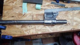
I'm actually quite surprised the nut is tight enough for that little stretch to bind, but it makes sense. When I got it, with the broken nut, there was only 3 threads of engagement...and it did feel tighter when closed than open. It would also explain why PIERCE's screw worked, and confirm the nut is not to blame.

It also stops sooner if I try running on backwards, those threads on the nut are tighter.

The nut for my Prentiss No. 4 has enough wear that that amount of stretch wouldn't matter, just surprised the tolerances on this Parker are still that tight. It may very well be that the nut (other than the dovetail) AND the threaded portion of the screw aren't original to the vise. Maybe when some of the damage happened it necessitated piecing it back together with misc. parts. I'll never know for sure.

So, now I'm wondering on a pair of solutions. Hand file, grind, sand, etc the screw threads and "thin" them out so the stretch has room to play in the nut (sounds like a horrible job...lol), or try some sort of lapping compound and try to "wear them in". I know the grit from lapping compound embeds in softer material, and removal completely is tough. I just don't know if it would ever become an issue in my lifetime of playing with the vise if I kept it well greased. If the idea even worked of course...:dunno:

I'm probably being overly optimistic about that idea...lol.

I do know from filing some high spots on the screw and cleaning up some gouges, I would not call it "hard." Not compared to an axe or hammer head at least. So maybe it could "wear in?"

Taking all ideas and suggestions...lol...of course I'll keep waiting for replacement parts to pop up, but not with held breath. It may end up collecting some dust for a while as I have a think on the whole thing. I don't need it to work, I just want it to work, so obviously there's a limit to the amount of time and $$ I'll give it. Not there yet though...:D
 

Attachments

  • 20210307_214154.jpg
    20210307_214154.jpg
    85.6 KB · Views: 25
  • 20210307_193904.jpg
    20210307_193904.jpg
    153 KB · Views: 28
  • 20210308_140350.jpg
    20210308_140350.jpg
    155.3 KB · Views: 28
  • 20210308_142323.jpg
    20210308_142323.jpg
    149.9 KB · Views: 27
  • 20210308_140326.jpg
    20210308_140326.jpg
    97.9 KB · Views: 25
  • 20210308_142457.jpg
    20210308_142457.jpg
    153.1 KB · Views: 27
  • 20210308_142302.jpg
    20210308_142302.jpg
    154.4 KB · Views: 28
Last edited:

Fretters

Well-known member
Joined
Jan 25, 2014
Messages
4,217
Location
South Yorkshire, England
Is it sad to admit that the thought crossed my mind to bore it out & make a combo taper pin & oil/cutting fluid pot? :D

The rounded groove marking the top of the taper sits at the top of the jaw.
 

Attachments

  • IMG_20210308_224111Z.jpg
    IMG_20210308_224111Z.jpg
    147.3 KB · Views: 38
  • IMG_20210308_223335Z.jpg
    IMG_20210308_223335Z.jpg
    129 KB · Views: 26
Last edited:

MattGavriloff

Well-known member
Joined
Jan 3, 2021
Messages
290
Location
Escanaba, Mi. South of Canada...
FRETTERS, btw being in my own little Parker land I forgot some input on swivel pin tightness. I only have the one Prentiss with a swivel jaw, and I still need to do just a tiny bit more smoothing in the pin hole, but to answer your question of play, currently with my pin pushed in place by hand, if I rock the jaw left and right, it moves enough to hear a "tick" but I can't really feel or see it actually move. I feel it's completely usable like it is, but I'll try for a bit tighter fit. I'm sure many left the factory feeling the same way.

Tolerance between the swivel jaw itself and the machined top of the body is snug as a bug in a rug....lol
 
OP
D

drivesitfar

Well-known member
Joined
Oct 23, 2013
Messages
36,114
Location
Pacific Northwest
MATT: sorry you are still having to work out some issues with your PARKER, but my thinking is you will figure it out so keep thinking about it while it sits for a bit.

Fretters: there is a good chance the tolerances were pretty good at the factory for these pins to drop to the bottom of their holes cause about 90% of the swivel jaw vises I find the pins are rusted in place and probably a good reason why they are still with the vise and not missing.

I like that little chain holder idea and wondering if it's stout enough for that big pin you made? how are you going to attach it to the pin or does that depend on how you finish the top if you are not quite done yet. I like it as it sits in the hole in that picture you posted and tell me (us) how your old swivel jaw works with it?
 

Fretters

Well-known member
Joined
Jan 25, 2014
Messages
4,217
Location
South Yorkshire, England
Cheers. :) Swivel jaws were never really a thing across here, as such, & the few that were made are thin on the ground, so obviously I don't have much to use as a yardstick with regard to gauging how they ought be. I know a lot more were made & appear over there though, so where better to ask than on here. :D
 

Fretters

Well-known member
Joined
Jan 25, 2014
Messages
4,217
Location
South Yorkshire, England
I like that little chain holder idea and wondering if it's stout enough for that big pin you made? how are you going to attach it to the pin or does that depend on how you finish the top if you are not quite done yet. I like it as it sits in the hole in that picture you posted and tell me (us) how your old swivel jaw works with it?


Not sure whether to use that chain with this new pin or not. The final design will probably dictate that decision. Since I tickled that taper, the swivel jaw seems rock solid now, when the pin's inserted. In fact, it may remain like that so that I've got enough to grip to remove it. It locks in quite well now. :D

I think there may be a hint of play between the post, (which the swivel jaw locates on), & the swivel jaw, but not enough that I'm going to start faffing with it, unless it ever becomes necessary. I'll never use this vice for any really heavy work, (I'd always favour my fixed No.7 for that), so it's not likely that I'll ever overly stress this vice.
 
To avoid these ads, REGISTER NOW!
Top Bottom