To avoid these ads, REGISTER NOW!

AC Diagonostic Tune Up Center ST-200

mike_z

Member
Joined
Jul 21, 2016
Messages
8
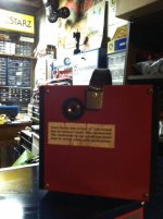
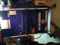
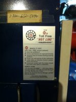
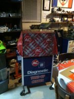
I was just given this ST-200 meter box. The reason it was free is because when it is connected to an engine, the engine dies. SO.... I'm looking for any information on this unit I can find. I'd like a schematic and an owners manual.

To date I got the voltage, dwell and RPM to work, but there are still some serious problems with the unit.

I'd appreciate any help, thanks Mike
 
To avoid these ads, REGISTER NOW!

George in Rancho Cordova

Well-known member
Joined
Mar 15, 2011
Messages
741
Sounds like a connection to the ignition primary is grounding the circuit.
Does it have a kill switch? If so, it may be stuck.

IIRC, the unit was made by Kal Equip and consolidated a number of functions into one box.
Perhaps some Kal Equip information is still around.
 
OP
M

mike_z

Member
Joined
Jul 21, 2016
Messages
8
No kill switch, at least that I can see (don't ask my wife if I can see). I've been looking for KAL and AC/GM equipment and documents. Looks like KAL was eaten up by another company some time ago and AC doesn't know anything about it, too old. I found a August 7, 1970 date inside. I've been attempting to trace out some of the circuits.

One question. Seems like there are neon lamps next to each meter scale. Should these light up for each particular test? Mine doesn't do that. Can't think of any other reason for them. Thanks Mike
 

DTE

Well-known member
Joined
Jul 13, 2013
Messages
996
Location
North Carolina
The Sun machines had 8 buttons to kill cylinders individually if all 8 were pushed in the motor would not start/run/
 
OP
M

mike_z

Member
Joined
Jul 21, 2016
Messages
8
Well.... still have not found any documentation for the ST-200. BUT... I opened up the battery connection module. It was a mess. The current shunt was broken off from the connection, there were broken wires, open wires and wires melted together. I also found that the high voltage leads were also all open and the sensor resistors broken. I'm not surprised by this. I'm sure that this unit was a gas station unit and most likely the leads were left on the ground and got stomped on and driven over. Maybe after repairing these leads more stuff will work. Let you Know Mike.
 

66vette

Active member
Joined
Oct 14, 2013
Messages
28
I have a ST-210, not all of the functions work. There are a lot of PC Boards making it more difficult to repair.
 
OP
M

mike_z

Member
Joined
Jul 21, 2016
Messages
8
I found out that ACTRON acquired KAL Equipment. I emailed ACTRON and they responded but were no help. Here is the response.

The item must have been made prior to our former owning company(SPX) acquiring KAL Equipment. We have no record of the tool at all. Unfortunately when KAL Equipment was acquired not all of the companies records were transferred and some information on tools was never given to us.


66vette, do have any paper work on your unit? I'd like to better understand what some of the tests actually do and how to do them.

To date, I have replaced most of the test lead wires and sensor parts. This has brought back maybe 60% of the functions. I have not been able to get the neon scale lights to work. If anyone has any documentation on the ST-200 I'd be interested in a copy. Thanks Mike
 
OP
M

mike_z

Member
Joined
Jul 21, 2016
Messages
8
Still no luck with documents, although I contacted a guy selling a ST-200 on eBay and asked if he would copy the manuals for my purchase. So far no response.

Well, as far as the neon scale lamps go, today I found (after tracing wires) an oscillator on the battery voltage card that is used to power the neon lamps. I found that the transistor DTG-110 was shorted. I replaced it with a 2N4398 and the oscillator started to work, but would not make enough voltage to light the neon. It needs more than 90 volts and I only had 55 volts. Turns out that the step up transformer had a bad secondary winding. I should have noticed the brown burn marks on it. So I found a small 120 to 6 volt transformer and wired it in and now the neon lamps work.

Next I have to assess which tests work and which don't. And check the calibration of the scales. But it so damn hot in the garage maybe this weekend when it gets cooler. Mike
 
OP
M

mike_z

Member
Joined
Jul 21, 2016
Messages
8
Still no luck with documentation. But, today I got the timing light to work. The xenon charge voltage was not working. One thing I noticed, this tool must be designed to work on 12 volt cars. I've been testing it on my 1939 Chevy and the 6 volt battery is marginal for lighting the neons. Sometimes they work sometimes not. The timing light will not work on 6 volts. Yet with a 12 volt battery these will work. On 6 volts, the voltmeter, RPM, dwell and those types of things will work. Does anyone have any experience running the ST-200 on 6 volts? Is what I say correct? Or is there more wrong with this unit? Thanks Mike
 

INSP380

Well-known member
Joined
Dec 17, 2012
Messages
895
Location
Cleveland, Ohio
Found it......
 

Attachments

  • page cover.jpg
    page cover.jpg
    147.8 KB · Views: 118
  • page 1 - Copy.jpg
    page 1 - Copy.jpg
    147 KB · Views: 130
  • page 2 - Copy.jpg
    page 2 - Copy.jpg
    150.3 KB · Views: 113
  • page 3 - Copy.jpg
    page 3 - Copy.jpg
    148.6 KB · Views: 108
  • page 4 - Copy.jpg
    page 4 - Copy.jpg
    145.9 KB · Views: 105
  • page 5 - Copy.jpg
    page 5 - Copy.jpg
    150.4 KB · Views: 104

INSP380

Well-known member
Joined
Dec 17, 2012
Messages
895
Location
Cleveland, Ohio
more...
 

Attachments

  • page 12.jpg
    page 12.jpg
    139.7 KB · Views: 108
  • page 11 - Copy.jpg
    page 11 - Copy.jpg
    142.9 KB · Views: 93
  • page 10 - Copy.jpg
    page 10 - Copy.jpg
    138 KB · Views: 89
  • page 9 - Copy.jpg
    page 9 - Copy.jpg
    150.1 KB · Views: 88
  • page 8 - Copy.jpg
    page 8 - Copy.jpg
    154.6 KB · Views: 86
  • page 7 - Copy.jpg
    page 7 - Copy.jpg
    150 KB · Views: 91
  • page 6 - Copy.jpg
    page 6 - Copy.jpg
    150.9 KB · Views: 90

INSP380

Well-known member
Joined
Dec 17, 2012
Messages
895
Location
Cleveland, Ohio
My unit...with retro fit HEI ..

Steve
 

Attachments

  • delco 7.JPG
    delco 7.JPG
    98.8 KB · Views: 78
  • delco manuals.JPG
    delco manuals.JPG
    95 KB · Views: 78
  • delco 8.JPG
    delco 8.JPG
    123.6 KB · Views: 75
  • delco 4.JPG
    delco 4.JPG
    89.2 KB · Views: 75
  • delco 2.JPG
    delco 2.JPG
    95.9 KB · Views: 77
  • delco 1.JPG
    delco 1.JPG
    117.5 KB · Views: 83
To avoid these ads, REGISTER NOW!
OP
M

mike_z

Member
Joined
Jul 21, 2016
Messages
8
INSP380, I really appreciate you posting this manual. I'll print it out and read it over. I'm sure it will help me getting this unit to work better. My machine is rougher than yours, pretty sure it serviced in a gas station for many years and got beat up. You show two operators manuals are they the same? I see that the one you posted was from April 1970. My unit has an August 1970 date on it.

Scanning the manual, I don't see anything about 6 volt testing. Everything is related to 12 volts so apparently it must have been only for 12 volts.

Today I hope to test the timing light advance delay stuff and maybe check the charging current stuff. Looks like after a few more days, I'll have a serviceable unit. I want to thank you for all the help. Mike
 

INSP380

Well-known member
Joined
Dec 17, 2012
Messages
895
Location
Cleveland, Ohio
Same book, different cover.

No problem, hope it helped. Mine is in very good shape and is mostly used as art in my collection.

Steve
 
OP
M

mike_z

Member
Joined
Jul 21, 2016
Messages
8
I hope to make this unit functional. I belong to a number of cars clubs, and there is always plenty of repairs that are needed. SO..... thanks again. Mike
 

Munkybarz

New member
Joined
Feb 4, 2018
Messages
2
Location
Owen Sound ON
Same book, different cover.

No problem, hope it helped. Mine is in very good shape and is mostly used as art in my collection.

Steve
Mike, thanks so much for getting the ball rolling, and a special thanks to Steve for posting scans of every page of the ST-200 manual. I've been trying to find this manual for the AC GM unit I have and you guys came through. Perfect!
 

6PTsocket

Well-known member
Joined
Mar 12, 2014
Messages
4,593
Too bad there was no schematic. I guess they intended to keep service in house. What happens if you use an external 12v battery or put another 6 volts in series with the 6 volt car battery to power the tester? As long as you have a common ground with the car, I think that might work. You are not feeding the 12 volts to the car.

Sent from my SM-G900V using Tapatalk
 

Jeff-kc

Member
Joined
Feb 25, 2026
Messages
9
I know this is a old post, but I'm getting desperate does anyone have an HEI box or plans on how to make one for this tester and any and all other manuals that go with it. Thanks.
 

Mintgrun

Well-known member
Joined
Oct 7, 2015
Messages
2,110
Location
Kingston, Wa.
I don't have this tester, but this advice may apply to your machine too. Apparently it will work on my Sun 404 tester, but I have not done it yet.

"To test an HEI distributor with a four pin module all you need is a 9V battery (you can find one in your smoke alarm), and two small jumper wires with alligator clips on both ends.

Connect your jumper wires to the 9v battery. The positive jumper connects to the wire that comes from the "B" terminal on the HEI module, and the negative jumper is grounded to the distributor body. The "distributor lead" on the tester that would normally connect to the points connects to the wire from the "C" terminal on the module, and the black "ground lead" grounds the distributor to the tester just like it does with a point distributor. The 9 volt battery has plenty of power to activate the module and the tester works the same as if you were testing a points distributor. I have done this a few times and it works great."

I took the quote from Farm Boy's post in this thread. (I've also seen the suggestion posted elsewhere).


Jeff-kc

Member
Joined
Feb 25, 2026
Messages
9
I don't have this tester, but this advice may apply to your machine too. Apparently it will work on my Sun 404 tester, but I have not done it yet.

"To test an HEI distributor with a four pin module all you need is a 9V battery (you can find one in your smoke alarm), and two small jumper wires with alligator clips on both ends.

Connect your jumper wires to the 9v battery. The positive jumper connects to the wire that comes from the "B" terminal on the HEI module, and the negative jumper is grounded to the distributor body. The "distributor lead" on the tester that would normally connect to the points connects to the wire from the "C" terminal on the module, and the black "ground lead" grounds the distributor to the tester just like it does with a point distributor. The 9 volt battery has plenty of power to activate the module and the tester works the same as if you were testing a points distributor. I have done this a few times and it works great."

I took the quote from Farm Boy's post in this thread. (I've also seen the suggestion posted elsewhere).

Thank you I really appreciate the help
 

Jack_K

Well-known member
Joined
Aug 7, 2021
Messages
332
Location
Australia
I don't have this tester, but this advice may apply to your machine too. Apparently it will work on my Sun 404 tester, but I have not done it yet.

"To test an HEI distributor with a four pin module all you need is a 9V battery (you can find one in your smoke alarm), and two small jumper wires with alligator clips on both ends.

Connect your jumper wires to the 9v battery. The positive jumper connects to the wire that comes from the "B" terminal on the HEI module, and the negative jumper is grounded to the distributor body. The "distributor lead" on the tester that would normally connect to the points connects to the wire from the "C" terminal on the module, and the black "ground lead" grounds the distributor to the tester just like it does with a point distributor. The 9 volt battery has plenty of power to activate the module and the tester works the same as if you were testing a points distributor. I have done this a few times and it works great."

I took the quote from Farm Boy's post in this thread. (I've also seen the suggestion posted elsewhere).

Without looking at the details of this analyser, I don't believe that will help. That is for testing a HEI distributor on a distributor machine without having the module from the car. I assume the box being asked about here is a thing which protected the analyser from the higher voltages form the HEI system. The Allen machines from the time had a box which did that.
 

Mintgrun

Well-known member
Joined
Oct 7, 2015
Messages
2,110
Location
Kingston, Wa.
Ah, I misunderstood the question. I was thinking of basic electronic ignition modules like Pertronix units that replace points with an "ignitor" and a magnetic ring that slips over the center post cam.

Thank you for clarifying. Hopefully @Jeff-kc will check back in and see your post.

Tom
 
To avoid these ads, REGISTER NOW!
Top Bottom