To avoid these ads, REGISTER NOW!

Help needed with structural details of steel entry gate build.

TimberMan

Well-known member
Joined
Apr 6, 2024
Messages
184
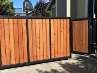
I have decided to weld up my own steel driveway gate but need some help in determining what size and thickness steel to use. The entrance will have a double leaf gate, each 8’ long as shown. I am trying to keep this reasonably light to minimize stress on the posts, help resist sagging and twisting but I am not looking to cheap out on materials.

From an aesthetic standpoint, the attached sketch shows the frame being made from ? X 3” steel tube which I think looks good but nothing is set in stone. I didn’t draw it to scale but I would assume that my pickets would be 1”x1”

If I could have some recommendations on size and thickness for the steel on this gate it would be a huge help.

Thx!
 

Attachments

  • IMG_2733.jpeg
    IMG_2733.jpeg
    439.1 KB · Views: 83
To avoid these ads, REGISTER NOW!

ehcsrop

Active member
Joined
Aug 15, 2024
Messages
34
Location
Lakewood, CA
I have a rolling gate 8' wide by about 6' H, hence no diagonal brace. The is one centered upright. I found that 2 x 2 square tubing is sturdy enough and I recommend 1/8th wall for light enough but easily weldable. I'd look at 3/4 tubing for the pickets. You could scale up from there to 3/16ths wall and larger sizes but it gets heavy quickly when you do that.

I just made sure the ends were capped off with good welds to keep moisture out. Any bolts may want some sealer like silicone but welded hinges for sure won't let water in. Another style hinge is a pin and socket with the socket side threaded for adjustment (highly suggested). Install a grease zerk in the socket which faces down.

I have another steel gate that is very decorative made from 1-1/4 tubing with 1/2 pickets, 7 feet wide by 7 feet tall and it is heavy. It sits on P&S hinges and once settled and adjusted it has remained aligned for several years. Keeping water out is imperative and if you keep the steel painted well the gate should last a long time. Heavy duty red oxide primer worked for me after a light phosphoric acid wash.
 

jack stand

Well-known member
Joined
Feb 29, 2012
Messages
3,305
Location
Lakes Region Maine
You're diagonal in your diagram will be the "workhorse" of this gate. This design is about the simplest and strong as it can be. I would use any dimension tubing of minimum 1/8" wall and not worry about it.
Don't skimp on your post and it's anchoring. The post is 50% of this strength equation!👍
 

carlaisle

Well-known member
Joined
May 14, 2022
Messages
361
In your design the pickets are little more than aesthetic, so you can make them as light as you want. 11ga is about 75% heavier than 16ga. That extra weight hanging off the lever makes a difference. 1/8" for the mains would be plenty. If you use round pickets you can easily run them straight through the diagonal. Weld on both sides and you'll have a very solid design. Increase the thickness of the members to get a sturdier design if that is your goal. The diagonal extending vertically past the horizontal doesn't provide any material structural benefit in this application. The gate posts and bases are what you need to focus on getting right the first time. Scale images can be a big help. Here's a start. 3" main members with 1" pickets at 4" spacing.

Scale gate example.jpg
 

KwikFab

Well-known member
Joined
Jul 27, 2024
Messages
1,168
Location
Central Valley, CA
1/8" will suffice using 2" square tube for the main frame.

When it comes to square tube, you can go thinner wall if you size up to larger tube vs smaller thicker stuff while maintaining strength.

As for @carlaisle mentioning of 4" spacing, that's to maintain code so a "sphere" can't fit between them (a child's head).
 

larry4406

Well-known member
Joined
Jan 27, 2006
Messages
19,043
Location
Northern Virginia
1/8" will suffice using 2" square tube for the main frame.

When it comes to square tube, you can go thinner wall if you size up to larger tube vs smaller thicker stuff while maintaining strength.

As for @carlaisle mentioning of 4" spacing, that's to maintain code so a "sphere" can't fit between them (a child's head).
The 4" spacing is the net gap where the child's head would trap. Not the center to center spacing. The picket diameter/shape affects the net gap along with the center to center spacing.

So if a picket of diameter/width D is used, then the max center to center is distance = 4+D.
 
OP
T

TimberMan

Well-known member
Joined
Apr 6, 2024
Messages
184
1/8" will suffice using 2" square tube for the main frame.

When it comes to square tube, you can go thinner wall if you size up to larger tube vs smaller thicker stuff while maintaining strength.

As for @carlaisle mentioning of 4" spacing, that's to maintain code so a "sphere" can't fit between them (a child's head).
Is that spacing in play for a gate? If so it Seems there would be a a point where it isn’t needed. For example, my 4-rail horse fence has more than 4” between rails.
 

KwikFab

Well-known member
Joined
Jul 27, 2024
Messages
1,168
Location
Central Valley, CA
Is that spacing in play for a gate? If so it Seems there would be a a point where it isn’t needed. For example, my 4-rail horse fence has more than 4” between rails.

Not for a gate most likely not, but threw it out there in case the OP wanted to implement it.

Unsure where the property is, if people walk by or if it's miles away from civilization.
 
OP
T

TimberMan

Well-known member
Joined
Apr 6, 2024
Messages
184
Not for a gate most likely not, but threw it out there in case the OP wanted to implement it.

Unsure where the property is, if people walk by or if it's miles away from civilization.
Thx. I did some checking and in my area the only time a gate needs to have 4” spacing is when it is part of a pool fence.
 
OP
T

TimberMan

Well-known member
Joined
Apr 6, 2024
Messages
184
In your design the pickets are little more than aesthetic, so you can make them as light as you want. 11ga is about 75% heavier than 16ga. That extra weight hanging off the lever makes a difference. 1/8" for the mains would be plenty. If you use round pickets you can easily run them straight through the diagonal. Weld on both sides and you'll have a very solid design. Increase the thickness of the members to get a sturdier design if that is your goal. The diagonal extending vertically past the horizontal doesn't provide any material structural benefit in this application. The gate posts and bases are what you need to focus on getting right the first time. Scale images can be a big help. Here's a start. 3" main members with 1" pickets at 4" spacing.

Scale gate example.jpg
Thanks! I didn’t think the extended vertical with diagonal was going to do much for strength but we like the way it looks. I don’t want to introduce any curves since it would be beyond my metalworking skills but the picture below was the inspiration behind the extended top / diagonal.
 

Attachments

  • IMG_2717.jpeg
    IMG_2717.jpeg
    350.8 KB · Views: 77

larry_g

Well-known member
Joined
Apr 28, 2007
Messages
16,869
Location
oregon
What is the gate intended to do? Do you have farm animals on one side? Is it manual operated or have an automatic operator? These play a bit into how strong the gate has to be. Another detail that you should incorporate into the gate is a wheel or shoe into the end so that when the gate is open or closed that it is resting on a pad so that the full weight of the gate is not trying to tip the hinge post.

lg
no neat sig line
 
OP
T

TimberMan

Well-known member
Joined
Apr 6, 2024
Messages
184
What is the gate intended to do? Do you have farm animals on one side? Is it manual operated or have an automatic operator? These play a bit into how strong the gate has to be. Another detail that you should incorporate into the gate is a wheel or shoe into the end so that when the gate is open or closed that it is resting on a pad so that the full weight of the gate is not trying to tip the hinge post.

lg
no neat sig line
This will be my driveway / farm entry gate but we do not raise any animals. The plan is to flank the gates with decorative brick columns which will need a footer so I plan to wet set the metal posts into quite a lot of concrete. We will have an automatic opener for the gate as well. I like the idea of a wheel to help support the load but the driveway is gravel so it will be easily disturbed and often irregular.
 

larry_g

Well-known member
Joined
Apr 28, 2007
Messages
16,869
Location
oregon
I like the idea of a wheel to help support the load but the driveway is gravel so it will be easily disturbed and often irregular.
You mainly have to support the gate when fully closed or open. Its nice if it can roll the whole swing but most of the weight constantly on the gate at each end of the swing is where the most problems start.

lg
 

nmk_61802

Well-known member
Joined
Mar 6, 2008
Messages
965
Location
Central IL
No comments on steel size, but your diagonal is opposite how I have always been taught to put them. As shown the weight of the far side of the gate is pulling down on the top portion of the post. Generally I have always been taught to start high on the far side and join low on the post side for a compression type brace.
 

mm08822

Well-known member
Joined
Jan 13, 2012
Messages
5,856
Location
NJ
The post AND its footing need to be large enough to not bend over time, but more importantly, the footing to not shift in the soil with this cantilevered load.

If the gate will be closed most of the time, then you only need to worry about it in one direction.

Also helpful, in the closed position, the gate is supported on the latch side to reduce the tipping moment.
 
OP
T

TimberMan

Well-known member
Joined
Apr 6, 2024
Messages
184
I know it may push me into having to hire out the welding since I have never welded aluminum before but should I consider aluminum to save weight or can I likely over build the post and footing enough to keep the loads in check?
 

Superbowl

Active member
Joined
Feb 19, 2026
Messages
40
Location
DC area
I like the idea of a wheel to help support the load but the driveway is gravel so it will be easily disturbed and often irregular.
Use a larger diameter wheel and a big spring pushing it down. It doesn't need to support all the weight, it is just a helper.
 

Firebrick43

Well-known member
Joined
May 12, 2015
Messages
13,989
Location
West central Indiana
No comments on steel size, but your diagonal is opposite how I have always been taught to put them. As shown the weight of the far side of the gate is pulling down on the top portion of the post. Generally I have always been taught to start high on the far side and join low on the post side for a compression type brace.
That is the proper orientation for a steel brace. Steel has much higher strength in tension/tensile than in compression, generally around 4 times. Wood generally has better compression vs tensile. But even then the archetype for the gate that the OP in post 11 is a very durable design that has deep historical roots especially in Britain, and made of rot resistant woods can last a generation or more.

There are several pages of the design in "Building doors and Gates" ISBN-10 ‏ : ‎ 0811726789

An excellent book for wood gates (and of course doors)
 

Firebrick43

Well-known member
Joined
May 12, 2015
Messages
13,989
Location
West central Indiana
I know it may push me into having to hire out the welding since I have never welded aluminum before but should I consider aluminum to save weight or can I likely over build the post and footing enough to keep the loads in check?
I wouldn't. I will create a whole other set of issues with paint. Just make the post solid, a H braced post would be also advisable and stronger than one massive post. And one main issue with post is frost heave. Make sure they are 4' deep at least and make sure any concrete is tapered but tapered in a cone not an inverse cone. Many dig the holes with the top larger than the bottom and the most massive pour will slowly be jacked out of the ground via freeze and thaw cycles.

One thing to be aware of no matter how you build it, make sure the vertical stiles go thru the bottom rail and they are open on the bottom. Same with the bottom end of the brace, leave it open. Also make sure there is enough weep holes drilled into the bottom of the horizontal members. No matter how well you think you welded it, water via condensation in air will get in and not only promote rust but will expand and burst the tubes when the water freezes.
 
To avoid these ads, REGISTER NOW!

jack stand

Well-known member
Joined
Feb 29, 2012
Messages
3,305
Location
Lakes Region Maine
I know it may push me into having to hire out the welding since I have never welded aluminum before but should I consider aluminum to save weight or can I likely over build the post and footing enough to keep the loads in check?
A cable or brace of some sort from the upper hinge down and out at a 45* angle (parallel to the closed gate) to a Deadman buried a couple of feet down does the same magic as the diagonal in the gate. Disguising it could be as simple as some shrubbery if you have visual concerns. If the gate is part of a fence on each side, this will be simple to beautify it.
A 20" round hole 3-4' deep with concrete around a 4" sch 40 electrical conduit would be a great choice for the 2 gate posts.
It will provide years of service and you can welding to it for your hinges then paint it to match.
I'd install them in this fashion without any opposing guy to a Deadman but watch for either post moving aut of plumb. You'll want this sturdy method to also support the gates while open!
 

cpakalolo

Well-known member
Joined
Mar 30, 2026
Messages
48
I know it may push me into having to hire out the welding since I have never welded aluminum before but should I consider aluminum to save weight or can I likely over build the post and footing enough to keep the loads in check?
If you can do steel, do steel. Aluminum isn't just hard to work with, It is hard to keep paint on it. The weight is something you can engineer around with heavier post footings and concrete ballast or counterweights.
 

Jackfre

Well-known member
Joined
Dec 26, 2010
Messages
4,406
Location
N CA
I built this gate for my daughters families house. I used 2x3x.019 and 2x uprights. It has a wheel. The gate is not used frequently. The stone clad post is the issue on this or about any gate. We do not know how it was built so I throw the laser on it on occasion. So far it is okay, but given the infrequent use I have a block under it too. The man gate on the rt is the primary entry to the back. For your situation I’d say good deep support post, good gate, otherwise you end up building a new hobby. If it is a corner post bigger/deeper. If on the run of the fence your diagonal support will go off the back of the post to another on the run.
 

Attachments

  • IMG_6113.jpeg
    IMG_6113.jpeg
    1.1 MB · Views: 46
  • IMG_6115.jpeg
    IMG_6115.jpeg
    1,019.7 KB · Views: 35

wssix99

Well-known member
Joined
Mar 2, 2011
Messages
5,155
Location
Chicago, IL
Unless you need it for aesthetic reasons, I would put the cross member from the bottom of the hinge post to the top corner of the latching side. (Reverse of what you have in the drawing.) That puts the cross member in compression vs. tension and will make the gate more durable.
 

Firebrick43

Well-known member
Joined
May 12, 2015
Messages
13,989
Location
West central Indiana
Unless you need it for aesthetic reasons, I would put the cross member from the bottom of the hinge post to the top corner of the latching side. (Reverse of what you have in the drawing.) That puts the cross member in compression vs. tension and will make the gate more durable.
If steel has higher tensile strength than compression strength why would it be more durable to be in compression?

In large steel trusses or steel truss bridges the tension members will be a fraction of the size of the compression members. It’s not always done in smaller ones due to ease of manufacture but as projects scale up many times it becomes the only way viable to keep weight under control.

Same goes for aluminum. Skins on the top of the wing of larger aircraft have to be significantly thicker and even stronger alloys to prevent buckling compared to the bottom skin in tension.
 

wssix99

Well-known member
Joined
Mar 2, 2011
Messages
5,155
Location
Chicago, IL
If steel has higher tensile strength than compression strength why would it be more durable to be in compression?
Its not the axial force on the steel diagonal but the radial forces on the frame. A square tube is probably stronger, but this is more problematic for round thin-walled tubing. Stress cracks can form around the weld where the tube is weak in this regard. If the weld isn't as good as we would see on a truss, the weld might crack also.

The weight of the gate will be on this cross member 24/7. Depending on how the diagonal is placed, it can be either in compression or tension. Compression comes with fewer issues.

That being said, I have used a cable with turnbuckles to stiffen a gate before and that cable, was (of course) in tension. However, the fittings went through the gate frame so the frame saw compression and all the pieces brought their strengths to the party.
 

eviltwin

Well-known member
Joined
Jul 1, 2019
Messages
92
Location
Norcal
IMG_2035.jpeg

Gate I build for my property. 2x2 .095 for surrounding. 2x2 .065 for the cross bars. 3/4x3/4 .065 for the pickets.

14ft Single swing with liftmaster weld on gate hinges. Don’t have a pic of it mounted on my phone but it works great. The gate is upside down in this pic.
 

Firebrick43

Well-known member
Joined
May 12, 2015
Messages
13,989
Location
West central Indiana
Its not the axial force on the steel diagonal but the radial forces on the frame. A square tube is probably stronger, but this is more problematic for round thin-walled tubing. Stress cracks can form around the weld where the tube is weak in this regard. If the weld isn't as good as we would see on a truss, the weld might crack also.

The weight of the gate will be on this cross member 24/7. Depending on how the diagonal is placed, it can be either in compression or tension. Compression comes with fewer issues.

That being said, I have used a cable with turnbuckles to stiffen a gate before and that cable, was (of course) in tension. However, the fittings went through the gate frame so the frame saw compression and all the pieces brought their strengths to the party.
Weld strength is easily solved by metal of sufficient gauge. For example, farm gates that are 18 gauge are garbage and will crack at the welds. 16 gauge gates cost a little more but will last longer with light use and you don't usually see joints crack as much. A 14 gauge gate is much stronger and if a bull gets randy the tubes just bend and kink instead of break off at the welds. And there is nothing wrong with 11 gauge on the main members and 14 on the vertical stiles

Second, with a diagonal member like that, the bottom should really pass thru the corner, cut a the bottom angle and the horizontal and vertical tube mitered to it. This allows drainage so water doesn't gather, freeze, and burst the tubes. The joints can have a gusset welded to the sides to ensure a bullet proof joint.
 

wssix99

Well-known member
Joined
Mar 2, 2011
Messages
5,155
Location
Chicago, IL
Here's an excellent video that does a better job than I did at explaining why a compression brace is stronger. In compression, the brace takes the load. In compression, the joins do...


Kaizen

Well-known member
Joined
Jan 9, 2015
Messages
6,938
Location
New England
I would advise doing one sliding gate if you have the room on the left or the right. So 16 foot opening needs about that on one side. One motor to worry about and probably less concrete. I did the below and it was my first attempt. I welded it on the floor of the garage then used my lift to pick it up and a cherry picker to move it outside. Then used a bobcat to position it. Even on an 8 foot section these things can kill so careful.
You are looking at 1200 pounds plus of concrete for posts on either design. That would save a day of labor if you ordered a truck.
IMG_7069.JPEGIMG_7093.JPEG
 
OP
T

TimberMan

Well-known member
Joined
Apr 6, 2024
Messages
184
A cable or brace of some sort from the upper hinge down and out at a 45* angle (parallel to the closed gate) to a Deadman buried a couple of feet down does the same magic as the diagonal in the gate. Disguising it could be as simple as some shrubbery if you have visual concerns. If the gate is part of a fence on each side, this will be simple to beautify it.
A 20" round hole 3-4' deep with concrete around a 4" sch 40 electrical conduit would be a great choice for the 2 gate posts.
It will provide years of service and you can welding to it for your hinges then paint it to match.
I'd install them in this fashion without any opposing guy to a Deadman but watch for either post moving aut of plumb. You'll want this sturdy method to also support the gates while open!
My plan was to oversize the footings I need for the brick columns and wet set the gate posts into them. Our frost line is only 1’ down so I won’t be 3-4’ in the entire hole, probably 3’ deep in the area of the post. When done, I would end up with 3/4 to 1 yard of concrete anchoring the posts in.

Alternatively, I have been thinking about welding a flange to the bottom of the posts and anchoring it to the concrete with nuts / threaded rod. I’m not an engineer so I don’t know how to size it but it would make it real easy to adjust plumb as things deflected over time and easy to replace when it rusts.
 

tarmy

Well-known member
Joined
May 28, 2014
Messages
4,658
Location
Nor Cal
I built this many years ago. 26’ cantilever…gate is about 8’ longer than that. Took several tries to get it stiff enough to deal 100 degree temp swings seasonally. The track is aluminum and the rest is steel. Weighs north of 800 lbs…maybe near 1k. Can slide it by hand easily. The posts are in about 4 yards of conc.IMG_2336.jpegIMG_2326.jpegIMG_2317.jpegIMG_2102.jpegIMG_2109.jpegIMG_2105.jpeg
 
OP
T

TimberMan

Well-known member
Joined
Apr 6, 2024
Messages
184
That is awesome! If I had the room I would consider it for sure.

BTW, the photo below is what I was considering as the flange concept but I am not sure if it would be as rigid or robust as wet set.

IMG_2770.jpeg
 

Firebrick43

Well-known member
Joined
May 12, 2015
Messages
13,989
Location
West central Indiana
That is awesome! If I had the room I would consider it for sure.

BTW, the photo below is what I was considering as the flange concept but I am not sure if it would be as rigid or robust as wet set.

IMG_2770.jpeg
Elevated flanges certainly can work if the concrete is sufficiently sized, reinforced, and the threaded rod is of adequate size. If a 65 foot stadium light pole with 6 lights can resist 75 mph winds on such a base, it can handle a cantilevered gate.

One advantage is the post can be adjusted to maintain plumb in the future if thing settle. One disadvantage is it will be a ground level and keeping dirt/debris from building up under the flange will be a pain so low.
 
OP
T

TimberMan

Well-known member
Joined
Apr 6, 2024
Messages
184
Elevated flanges certainly can work if the concrete is sufficiently sized, reinforced, and the threaded rod is of adequate size. If a 65 foot stadium light pole with 6 lights can resist 75 mph winds on such a base, it can handle a cantilevered gate.

One advantage is the post can be adjusted to maintain plumb in the future if thing settle. One disadvantage is it will be a ground level and keeping dirt/debris from building up under the flange will be a pain so low.
Any idea if it will be less robust than wet setting the post in concrete? it seems like at some point the posts will rust out and if wet set into the concrete that also serves as the footing for brick columns then I would have a pretty big challenge on my hands to repair / replace.
 

Stuart in MN

Well-known member
Joined
Sep 8, 2005
Messages
23,000
Location
Minneapolis
I think the elevated flange is the way to go. Embedding the post in the concrete will cause rust problems, if its sitting on four studs with nuts it won't have water collecting around the base. Include a little weep hole on the bottom, any water or condensation that gets inside the post will drip out on the concrete and run away.

Going back to your sketch in the first post - if possible include a diagonal from the top of the post down to the ground (to the left in the sketch) to help carry the weight of the gate. It doesn't have to be tubing, since it will be in tension a steel cable that's tied down to an eyebolt set in concrete would work.
 
Last edited:

nadogail

Well-known member
Joined
Jan 23, 2009
Messages
31,907
Location
Coronado, CA
Whenever I have any doubts about the strength of something I am building, I always “Go For Stout”.

A little more material or Welding Rod seems to be better than having to build it over again the next time you have to build it.

If in doubt, Build It Stout.
 
OP
T

TimberMan

Well-known member
Joined
Apr 6, 2024
Messages
184
Whenever I have any doubts about the strength of something I am building, I always “Go For Stout”.

A little more material or Welding Rod seems to be better than having to build it over again the next time you have to build it.

If in doubt, Build It Stout.
Do you think 1/2” plate is thick enough for the flange?
 

nadogail

Well-known member
Joined
Jan 23, 2009
Messages
31,907
Location
Coronado, CA
Half inch steel should be sufficiently strong for your purpose.
If you needed it to stand up to Armor Piercing ammunition, you should go back to the Drawing Board.
 
To avoid these ads, REGISTER NOW!
Top Bottom