To avoid these ads, REGISTER NOW!

rattle_snake's random shop projects v0.1

OP
R

rattle_snake

Well-known member
Joined
Jun 25, 2015
Messages
5,175
Location
Chandler, AZ
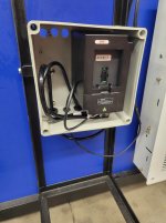
Spent an evening doing electromechanical troubleshooting on the CNC router. Same as my day job, something broken in several ways and have to peel the onion and solve each layer one at a time. Went from 90% done to 89%.

Still not sure what exactly is wrong with the Y axis steppers. One motor runs at twice the speed of the other. Swapped drivers, same result. So for now I have set the step count to 2x so they run together. Motors are unknown, no markings. The right stepper is slightly bound up with it's ball screw and needs some more modifications. Should have put connectors on the motor wiring so they can be swapped around.

The x-axis drive coupler I made myself is not staying tight. Should probably buy one that fits better. Limit switches are working.

The z-axis stepper drive was junk. I removed it, pulled the PCB and did visual. Input diode cold solder joints. Fixed that but still overheats immediately so swapped in a slightly different one. Control wiring was backwards. Limit switched were not wired properly. Fixed all that and it's running properly.

Spindle wouldn't spin. Had voltage on input, and signal on FOR terminal. Went through the programming of the VFD. Was able to get it to run on the front panel controls, and went back one step at a time to the external controller. The jumper on the board I moved first is labeled backwards. But now it moves. The spindle motor was noticeably warm for having run only a few seconds. Have to assume that while I was trouble shooting at 0 RPM the coils are still driven. The spindle must be liquid cooled. I programmed a minimum speed so this should not happen again.

The coolant pump is not being activated. The relay was not wired correctly. Resolved that but cannot find a setting to turn it on with the spindle, appears to only do that in g-code. So have some options, can connect it with the spindle signal, or just have it run whenever power is on. When spindle is not commanded on, it doesn't drive the coils, but need to verify that again.

So now it moves in all three directions and spindle runs. But a long way to go still to finish. Need to fill the coolant tank and test the system.
The controller is complicated and will require some time to learn it's setup configuration and basic operation. Still need to construct the bed and shelving. Then figure out power receptacle.
 
To avoid these ads, REGISTER NOW!
OP
R

rattle_snake

Well-known member
Joined
Jun 25, 2015
Messages
5,175
Location
Chandler, AZ
I took the time to make all the stepper motors removable and be installed in any location. Swapped the Y motor and same result. So that only leaves the ballscrew pitch. Put a dial indicator on the gantry and rotated one rev. One is 10 mm 'lead' the other is 5 mm. So I bought the wrong lead. And it was a PITA to turn as I didn't understand all the details enough to buy one machined.
Stepper motor drives happen to have convenient DIP switches to set the rotation counts per pulse, so....
 
OP
R

rattle_snake

Well-known member
Joined
Jun 25, 2015
Messages
5,175
Location
Chandler, AZ
Still not able to make the y-axis perform acceptably. The left side with the 10mm ballscrew seems to work fine with any motor. The right side struggles and will stall with any motor. I can slow down the motors and make it work, but once the system is loaded with the cutter I'm worried it will stall and ruin material. Already running the stepper drives at full current which is 4 A, motor tag indicates 3.x amps.

The right side has the 5mm ballscrew and in theory should have more torque as the gantry moves less per rotation. I noticed that when tightening the drive arm the drive binds up, so I machined 0.025 off the spacer and it is better. I switched the motor coupler to a mis-alignment type and fine tuned the motor alignment. It turns OK by hand. All of the ball screw shafts have some degree of runout.

The fixed couplers get stuck on the shafts easily. Tried to pry one off and realized the motor armature was already bent some. Had to cut the coupler off, managed to break off a mount ear as well. Put that motor on the x-axis and it seems to work fine.

Buying another matching y-axis ball screw is an option. The 5 mm pitch one would seem to be a better choice. Before that I should swap the ballscrews side to side and see what happens.

I also have a pair of much larger motors. They would take a completely different mounting scheme. Not sure how much better they would be with same drive amperage. Larger diameter/longer arm on armature should have more torque with same magnetic force.
 
Last edited:
OP
R

rattle_snake

Well-known member
Joined
Jun 25, 2015
Messages
5,175
Location
Chandler, AZ
Received the replacement left LCA for the CV IFS. Even though it has a new ball joint, it doesn't match the other new one, and I have one that does. I figured I could possible ruin the new assembly pressing the BJ out and seeing if it is standard size or not, and put in the MOOG joint. But before that, waste time slicking out the casting.
The arm BJ surface isn't flat and the machined cup is too small for any pipe I have, so somewhat delicate to get in and out in the press or BJ C-clamp. I managed to have the lower sleeve partially on the BJ lip when pressing out and it tore part of the lip off. Fortunately the bore was standard size and I was able to press the MOOG BJ in.
I wanted to get all the parts off my table so I modified a dolly to hold the entire assembly. It is not balanced so used some uni-strut to secure the front side. Put all the part loosely together. Last thing to do is order the remaining fasteners.
PjxR4W98gUMfdJMdBZuQ=w1215-h911-s-no-gm?authuser=1.jpg

Still not decided on how exactly to mount to the frame. I have some ideas, have to wait until things are cut out and apart to decide.
_EKe-qm8Ff8xTkdvtfZIQ=w683-h911-s-no-gm?authuser=1.jpg
 
OP
R

rattle_snake

Well-known member
Joined
Jun 25, 2015
Messages
5,175
Location
Chandler, AZ
Float the nuts in their mounts w/o allowing any rotation about or translation along the lead screw axis?
Big(ger) single motor with a cog belt to drive both lead screws?
I assume that you're using a coupler like these? https://helicalcouplings.com/product-category/clamp-couplings/ Thought about going to a Oldham type design? Can likely make those yourself.
Loose bolts make it work but not a end solution. Have bigger motors.
Yes using the helical only on the right Y-axis for now.

Had a chat with the guy I got the parts from, he mentioned that the steeper ballscrew pitch can engage more balls/rows and have more drag. Likely why he bought bigger motors.
 

ntsqd

Well-known member
Joined
Jan 22, 2005
Messages
960
Location
Lower left coast
I think that I understand how the CV cross-member is supposed to bolt into a CV (only those 4 bolts?). How do those bolt holes align with the truck's frame, and can the frame sit directly on the cross-member and result in the desired ride height?
Or is that the problem that you mentioned above?
 

PugetDude

ALLIANCE MEMBER
Joined
Mar 13, 2013
Messages
22,346
Location
Superstition Mountains, AZ
I think that I understand how the CV cross-member is supposed to bolt into a CV (only those 4 bolts?). How do those bolt holes align with the truck's frame, and can the frame sit directly on the cross-member and result in the desired ride height?
Or is that the problem that you mentioned above?
IIRC, it takes about a 1/2" thick spacer between the CV crossmember and the existing frame to get it in the correct mounting location?
 
OP
R

rattle_snake

Well-known member
Joined
Jun 25, 2015
Messages
5,175
Location
Chandler, AZ
I'm wanting to alter the wheelbase, french it up into the frame rail (to sit lower), and brace/fortify the frame in general. A typical pickup ladder type frame has limited resistance to twist, and when you cut out the cross members it gets worse. So my plan is to brace and strengthen the chassis but with minimal weight added and designed for ease of maintenance. So bolt in braces, select frame boxing areas, x-braces, gussets and so on.
The K member is a structural piece, but I don't want it to be the only one other than the one at the rear of the frame.
I've abandoned the plan to build a complete new frame. No matter how much time money and effort I put into it, it won't be any better than what anyone with deep pockets can just go and buy.

Back to shopping four link kits. Thinking parallel w/ panhard vs triangulated, although triangulated can be done with multiple mounting holes to adjust squat. There are different levels of kits available. Considering buying brackets as my plasma doesn't make perfect holes, and there are a lot of holes. I could make it work, but don't really want to. The bars don't necessarily have to be in the same plane as one another. Can be under, inside or outside the frame rail. I think with the existing fuel tank behind axle, the airbags will have to go someplace else.
 
OP
R

rattle_snake

Well-known member
Joined
Jun 25, 2015
Messages
5,175
Location
Chandler, AZ
Decided to try the larger motor on the right side instead of swapping ballscrews for testing. Even if the issue is that the one screw needs more torque, they are expensive and I have the motors for free. Designed some nema 34 style brackets with locating tabs and cut them out of 1/8" steel on the plasma.
VJC_7K_lJ1Y1mQeRCCYDQ=w683-h911-s-no-gm?authuser=1.jpg

Abandoned the rivnuts and welded the bracket to the frame. Used a hunk of bar to measure the placement error, can get it just right within the <1mm of slop in the pilot hole. Also used it to measure the ballscrew location and decide if I wanted to start over and make a new design. I didn't want to shim or offset either, because the arm is fixed and the ballscrew needs to be parallel to the guide rail. So everything has to be centered on the frame better than 0.010" or so.
m1ZZ1C9FmJnlP5M0wbKSw=w683-h911-s-no-gm?authuser=1.jpg

I went ahead and made one rigid coupler for alignment and testing. The 34 motor has a 14 mm shaft and has almost 3x the torque as the 23. This particular one is rated at 5 amps, although the drive is only 4. I was able to use washers to shim the ballscrew mounts out the needed amount and test it. Still stalls if it moves far enough. The ballscrew/mounts/motor turns by hand OK, but something is still not right.
 

ntsqd

Well-known member
Joined
Jan 22, 2005
Messages
960
Location
Lower left coast
No idea why they did it that way (rules didn't allow boxing the frame, maybe?), but I once saw a Class 8's frame that had been altered with a diagonal lattice of small tubes. Think a diagonal vertical zig-zag of tubes running from the front suspension mounting point all the way back to the rear rear suspension mounts. Adds torsional stiffness and doesn't block access to all of the usual stuff run on the inside of a channel frame like the far more common boxing of the rails does.

I'm reasonably sure that a single converging or a double converging 4 bar linkage will have a higher roll center than a non-converging with a panhard or trac-bar design. Unless you deliberately place the trac-bar quite high when most place them low. If you're concerned about a trac-bar causing lateral translation and possibly putting a tire into the fender could replace it with either a Watts linkage or a WOB linkage. Within a reasonable suspension travel range neither of those has any lateral translation. It would be interesting to plot the CV's Roll Center as that could make the decision for you.

We tried to use an Oldham Coupling on the small engine dyno and it was marginally successful. Worked well for the continuous power, just couldn't handle the very large impulses. We had the middle piece made from brass.
ds%2F2022%2F06%2FParts-of-Oldham-Coupling-1024x472.jpg
 
OP
R

rattle_snake

Well-known member
Joined
Jun 25, 2015
Messages
5,175
Location
Chandler, AZ
I haven't put much thought into the roll center of the rear links. I believe the 4-link calculator I use will do so. In general, where I live, my definition of 'street use' is stoplight to stoplight in a straight line. Not much high speed cornering. I still want a frame that is decently rigid, but the rear suspension is to be optimized for launch from a stop. 60'.
 

ntsqd

Well-known member
Joined
Jan 22, 2005
Messages
960
Location
Lower left coast
So no speed runs up Oak Creek Cyn? LOL, like you ever could with all the tourons up there...
Helped TZ move from Wilson up to 16th & something, got a good idea of the rectalinear lay-out of those streets. Felt a lot like driving around the San Fernando Valley, only hotter. Which I hadn't thought possible.

I know that ExcelCAD does calc the RC, at least the older version that I have does.
Double converging is easy to mentally model (for me anyway). It's on the axis between the convergence point for the lower links and the convergence point for the upper links and the plane of the rear axle center-line.
And panhard bar is even easier, it is where the height that the bar attaches to the axle housing at the chassis center-line plane.
Single converging is the one that I forget how the non-converging links are handled in setting up that axis. Could simply be where an axis passed thru the front mounting holes passes thru the chassis center-line plane, but not sure of that.

RC will matter to drag type launches, although obviously not nearly as much as anti-squat. I don't know a heck of lot more than that about drag set-ups.
Although I'd at least look at it I think that I'd pay more attention to any tendency for rear-steer in what you're wanting than where the RC is. Over-steer is fun when you're ready for it, and scary, don't need a seat-belt, leaves a circular stain in the seat when you're not.
 

zanyad

ALLIANCE MEMBER
Joined
Apr 26, 2018
Messages
2,760
Location
NE Ohio
Well I tried lubricating the problem ballscrew and it seems to be running better, made a whole trip and back without stalling. Been sitting 12 years exposed. but AZ so practically zero rust. :cool: .
Glad it seems to be the easy (and cheap!) fix. :pimp:
 
OP
R

rattle_snake

Well-known member
Joined
Jun 25, 2015
Messages
5,175
Location
Chandler, AZ
Lube didn't 'fix' things, improved, but still not acceptable.
Spent a lot of time on the CNC router project over the weekend. I'm at the 'I didn't come this far only to come this far' point. Going slightly backwards on progress, now at about 88%. But have to put more money in.

I swapped the y-axis ballscrews. As expected mixed results, now neither side works properly. I think it is just a case of accumulated issues, one side had many the other few.

I filled the coolant tank with distilled water and tested out the system. Made a splitter for the spindle output to run the coolant pump as well. Doesn't work. Relay not activated. The output is an isolated opto-coupler. It doesn't need it to be isolated so connect it's ground to the 24V system. Ran a dedicated wire for it with some spares. Still doesn't have enough current to turn relay on even though I bought one within the rating. Fine, hard wire the relay on when power is on. Pump still not working. Voltage at the terminals. Banged it hard on the ground and it runs. So pump is not reliable, junk. Put it into the tank and verified flow through the system. Connections started leaking liquid onto the MDF. Started up the spindle, it ran for 5 seconds and started to let the magic smoke out. Shut system down, put my had on the motor and it was warm but not hot, coolant running still and it cooled quickly. At that point I called it a failure for the day.

Next day got pump running and tried spindle again, same result, hot and smoke. So it is trash. Decided to abandon the water cooled aspect of the project. Seems to not go well with a machine made with MDF, is going to continue to leak and be a problem. Instead buy an air cooled spindle. Found one for about $175, 2.2kw same as the other. Ripped out the coolant lines. Swapped back to a smaller drag chain on the y-axis. Removed the tank and pump. Left the relay and receptacle in place but not connected.

Cut a piece of 1/2 MDF for the lower bed.
npwsjfX3ikvw4GdLTGdQ=w1215-h911-s-no-gm?authuser=1.jpg

Installed the t-track and used the leftover 1/2 MDF for spoilboards. I don't think that 1/2 is tall enough as it leaves only 1/8 to the t-track. Didn't go to the effort to secure it yet. Need a plan first, likely t-nuts.
ndVIw7wAPYPIWEsl-fHNA=w683-h911-s-no-gm?authuser=1.jpg

Installed the 2nd nema 34 motor on y-axis. Mounted the motor plate on a piece of flat bar, that could then be welded to the frame. Covers the holes, and is minimal spacing outward. Need to go back and re-do the other side. Calculated the spacer needed for the bearing blocks and made some round spacers out of DOM that fits over the riv nuts. Used a counterbore to square off the beveled countersinks to be able to use a SHCS instead of a flathead, to have adjustability.
Doesn't make it work any better. Decided to abandon the cheap stepper drivers. Swapped out the x-axis driver for the better quality one that has sufficient capacity for the nema 23 motor. Ordered two more of two sizes more current, enough to fully drive the 34's 5 amp coils.
XbPLjRW-TgXMXsuLUMxrg=w683-h911-s-no-gm?authuser=1.jpg

Less clutter on the machine with coolant system gone. Left the tank bracket for now.
AFCck0dkqLWBQMdVFNzsQ=w683-h911-s-no-gm?authuser=1.jpg
 
Last edited:
OP
R

rattle_snake

Well-known member
Joined
Jun 25, 2015
Messages
5,175
Location
Chandler, AZ
Reworked the right y-axis motor and bearing block mounts to match the other side. Do a better job. Tried to save the old old motor plate but it was mangled by the time I had cut and hammered it off. So instead just press a few buttons and cut a 3rd one.
oSARQ9S5G2J_kXFs6jDQ=w1215-h911-s-no-gm?authuser=1.jpg

Alignment came out decent. The change spaces the ballscrew farther from the gantry so had to modify the spacer. Ended up using two of the previous spacers that worked out decent. The forward bearing block spacer was 1 mm shorter than the rest, so perhaps part of the problems on that side.
In general, the y-axis drive arm would be better if was not rigid in all directions. Float in z and x directions. Just how to do that with no y-slop
99ofeV6khzv-7ClEmxdw=w1215-h911-s-no-gm?authuser=1.jpg
 

ntsqd

Well-known member
Joined
Jan 22, 2005
Messages
960
Location
Lower left coast
Orient shoulder bolts in the direction(s) that you want to allow some freedom of movement. Run them thru reamed to size holes, not merely drilled. May need to experiment with hole size to achieve desired ease of allowed motion while staying within tolerable slop in other direction(s). If there is a binding problem between the bolts one shoulder bolt can run thru a reamed hole while the other is in a small slot oriented to point towards the reamed hole. Reamed hole provides restriction of movement in all but coaxial and rotation about it directions. Slot stops the rotation.
Possibly include a stack of Belleville washers on those shoulder bolts. That will reduce or eliminate any slop in the allowed motion direction.
 
OP
R

rattle_snake

Well-known member
Joined
Jun 25, 2015
Messages
5,175
Location
Chandler, AZ
The larger stepper drivers arrived. They are a physically larger format so nothing will fit like before. Current capacity is beyond the 5 amps RMS of the nema 34 motors. Fan cooled.
c07O1FV1e5aimZwl734w=w1215-h911-s-no-gm?authuser=1.jpg

I made a parts carrier for the two smaller drivers to fit within the space that is left.
xbsJ_MxF2FIujf1kwdBQ=w1215-h911-s-no-gm?authuser=1.jpg

UMXiHjvmeafSC6sMAUykg=w683-h911-s-no-gm?authuser=1.jpg

I directly mounted the larger drivers to the enclosure. They use smaller control connectors so had to rewire that aspect. Also re-terminated the power and motor leads with ferrules. Now every wire has a ferrule. 3rd rewire job.
HkQNrrT3SelUQnH17YaVA=w683-h911-s-no-gm?authuser=1.jpg

New air cooled spindle. 220v 3-phase 2.2kw//3hp. ER20 collet.
7rcNxzmRfnEhQ1MqYVv_w=w683-h911-s-no-gm?authuser=1.jpg

Once all the new parts were installed I tested out the y axis and it seems to work OK at a slower speed. I installed grease zerks on the guides and ran it back and forth a few times. The holding torque is much higher, cannot move the motors now when energized. Ordered some more zerks for the x-axis. Now that it is properly lubed, aligned and more torque I can see it if will run at higher speeds. Thinking I can make the spoilboards as first project and use the machine to countersink all the fasteners.

The connector on the new spindle was different so had to solder it on. Forgot the nut so did it twice. I put a bit in the spindle and tested it out. It ran for about 5 seconds and the magic smoke poured out. again. HOT!

So went from happy with forward progress to disappointed and defeated. I shut down the shop and called it a night. If it was easy everyone would be doing it.

I think the VFD is damaging the motors. I'd say that at least one power FET is shorted or damaged and sends full DC current to the motor and fries it. The DC voltage is in the 300 V range.
I had thought that the water cooled spindle was faulty or I had run it at 0 RPM dry/hot while programming and troubleshooting. Now I think it was fine and no current was flowing at 0 RPM. Clearly the current limit protection didn't work. So it will go into the trash with the other four **** stepper drives. Got what I paid for out of them (free). I have not tested or did autopsy on the damaged motors. They spin fine and may still work. I don't want the water cooling aspect, so that one isn't useful. The air cooled one might still work, but obviously is damaged to some extent, and is likely to fail. Winding insulation is burned. With my luck it would fry the new VFD.

Can't stop now so wasted more money on another spindle and a new VFD. This time I ordered a 110V input, 220V 3-phase output, 2.2kw VFD (as apposed to a 220v input). Plan is to put the 110v input unit on the drill press, and use the 220v from the press on the CNC router. Will see if the 110v one trips the GCFI.

Could also go the other way, however the router has a larger 3 hp motor (drill press is 2 hp, 1.5kw) and is already at the limit of a 120V circuit, almost 20A, not including the power for the steppers. So the router will stay 220V and the drill press converted to 110v. I can only assume that the VFD won't fit/bolt up to either of the existing mounting schemes.
 

tarbellb

Well-known member
Joined
Apr 17, 2011
Messages
5,742
Location
Oregon
Just got done setting up my 1ph to 3ph spindle motor on VFD

I know you're well versed in much of this, did you confirm your spindle hz setting for the vfd?

Spindles specifically run a much higher hz, 400+ typically. My manual wasnt the best resource for setup so I plugged my specs into Ai, provided some more reference points to double check my inputs. Just a thought

All that being said, it still runs hot... 130-160f and haven't hit it w a full load yet...
 
To avoid these ads, REGISTER NOW!
OP
R

rattle_snake

Well-known member
Joined
Jun 25, 2015
Messages
5,175
Location
Chandler, AZ
Tinkered on the CNC router last night. Installed m6 grease zerks on all the blocks and nuts. Bought a cheap 90* slip on grease gun adapter. Didn't fit at all, touched it up on the belt grinder to be usable. Going to get a clamp style one.
Tried to speed up the steppers on x-axis, it stalled near ends of travel so I turd polished the drive arm length in the mill to get it to fit just right. Still stalls at a higher speed, although one step down it has plenty of force and will push me over if I put my hand on the spindle.

Same for y axis, one step up and it doesn't work at all. I should know why this is given what I do, so something to learn.

I removed the suspect VFD and prepped it for the trash can. Don't want to take the drill press out of service so have to wait a few more days for the new VFD to arrive and begin the swap process.

Bought 2 sheets of 3/4 MDF to make spoil boards and shelving. Can't quite decide on how exactly to do either so left them in one piece. Thinking vertical dividers may be better than horizontal shelving. Or some combo.

When the machine build is done, that is only the beginning of having the entire workflow figured out. CAD CAM & cut.
 
OP
R

rattle_snake

Well-known member
Joined
Jun 25, 2015
Messages
5,175
Location
Chandler, AZ
Just got done setting up my 1ph to 3ph spindle motor on VFD

I know you're well versed in much of this, did you confirm your spindle hz setting for the vfd?

Spindles specifically run a much higher hz, 400+ typically. My manual wasnt the best resource for setup so I plugged my specs into Ai, provided some more reference points to double check my inputs. Just a thought

All that being said, it still runs hot... 130-160f and haven't hit it w a full load yet...
Yes I programmed the frequency limits in addition to the other relevant parameters. Min 20 max 100 to start. Spindle is rated to 400 Hz.

Gotta love the documentation that these come with. If you know what you are trying to do, the poor translation can help. Otherwise it can be very confusing.

3hp will make a lot of heat, 2.2 kW.

A VFD is almost identical to an audio amplifier. DC stage that makes a square/sine wave. H bridge. If one FET is bad, it takes out the load. Good equipment has protection that works. Cheap import junk claims protection that doesn't.
 
OP
R

rattle_snake

Well-known member
Joined
Jun 25, 2015
Messages
5,175
Location
Chandler, AZ
Spent another evening going backwards on the router project. I think I'm back to 85% done now. It's what I do for fun?

I've avoided finishing out the limit switches. The y-axis was left, so I decided to get it done. Moved the head to left front corner and the spindle hits the VFD and control box. Measured the new VFD and it's mount is completely different. So removed the tower and cut off the mounts. Moved the control box farther out.
QrEPO0rbdHlo9jQW87DQw=w683-h911-s-no-gm?authuser=1.jpg

Y Min limit switch. M2 hardware, tiny. Hands shake, issues with central processor.
CLP8wUgVTJ2feYgpllJg=w1215-h911-s-no-gm?authuser=1.jpg

Y Max limit switch. Couldn't really mount the switch out of the crash path, but protected by the steel mount below it.
pukzgqM1iPyIPBgvg1kQ=w1215-h911-s-no-gm?authuser=1.jpg

Plan is to mount the new VFD on the back of the machine with the rest of the gear. Much shorter path for power and motor connections. Put a 3 conductor control wire back in that I had just removed for the cooling system. The VFD does have a remote mountable control panel, however the controls don't do anything when programmed for external command. So not very useful, and the ribbon cable is too short to reach the controller. It is an odd size 0.050 pitch, and can only get pre-made cables in 5' max length. I could extend what I have if I want to. Might have parts at work.

I put the replacement spindle on and a bit in it to cut myself on. Programmed the controller to 'Merican units and tested out the scaling. X and Y were right on, I have the calculated 43" x 50" of usable travel between the limit switches. The Z was off by a factor of 2, so fixed that in configuration setup. Z axis has only 2" of travel, which is not much. I can move the Z-axis up farther if needed.

Still not decided on the storage or spoil board plan. Thinking I may just glue 3/4 spoils on in between the t-tracks. Surface as needed, glue more on later. Unless I'm cutting a large sheet, I can use something specific for the task.

Farted around in Fusion trying to make a simple cut file. One circle. Create a tool. Going to have to spend some time learning how to set up the entire workflow.
 

Ohmthis

Well-known member
Joined
Jan 20, 2013
Messages
3,009
Location
Outside of Louisville KY
Justin, I have done the CV swap on my 66. I used a kit that located the crossmember. Even with wanting to modify your frame, I’d go with it. It definitely accelerated the process and I didn’t have to drill a bunch of holes to make it fit. What are your our plans for the rear mount on the LCA? I looked at modifying the stock mount. I didn’t like how it would look from seeing others. Looking into the aftermarket, I saw several “fabbed” options. I didn’t like them either. I ran into a mount made by Range Industries. It looks much better aesthetically. It has shims that can be added or removed for the alignment. I have pictures of it on my build here.

What VFD are you using on your router project? Ive converted a big drill press and a lathe. Hitachi and Fuji were what I used.
 
OP
R

rattle_snake

Well-known member
Joined
Jun 25, 2015
Messages
5,175
Location
Chandler, AZ
I'd have to modify any type of pre-made bracketry as the IFS assembly isn't going into typical location. And I'm cheap so difficult to spend money on something I can make custom with scrap. Not sure on the rear LCA mounts, will see what has to happen when I get to that point. The rear bushings are really sloppy so they don't have to be adjustable. The adjustment is the slop then clamp/tighten the nut.

I use cheap import junk VFDs. $100.
 
OP
R

rattle_snake

Well-known member
Joined
Jun 25, 2015
Messages
5,175
Location
Chandler, AZ
Moved some stuff around on welding table. Looks more cluttered but easier to reach and use. Bought another paddle grinder and got rid of corded grinders other than a 7" with a diamond for concrete. Bought a pair of 4.0 Ah m12 batteries for the red tools, and another charger. Milwaukee charger is flakey, like the batteries. Dewalt stuff is always solid, more robust.
4c33l2MdODm1itekeTLw=w1215-h911-s-no-gm?authuser=1.jpg
 
OP
R

rattle_snake

Well-known member
Joined
Jun 25, 2015
Messages
5,175
Location
Chandler, AZ
Added some forward facing work lights on the tractor, up high. Pallet piled high with bags of **** blocks the headlights. Made some stout brackets to mount the lights on the canopy frame similar to the rear.
L65c8H27dTfi-uyqXB8w=w1215-h911-s-no-gm?authuser=1.jpg

Ran the wiring inside the tubing.
jtcFmcU8zxlI7FkQfjaA=w1215-h911-s-no-gm?authuser=1.jpg

Under the lid out of the weather.
DRT4Zyrkp10yYShq2ouQ=w1215-h911-s-no-gm?authuser=1.jpg

When I did the rear lights I added an extra fuse/realy/switch for future expansion. Got to thinking and decided that I could repurpose and expand the existing lighting wiring. I ran a double circuit to both sides, for the dual color lights. This is 6 conductors, so can have up to five circuits and GND. More practically, 4 circuits, two each side. So I rewired the rear lights to share only one side of the wiring run to the canopy. On the other side, I used one of the circuits to power the front lights, and left it connected to the existing switch for the white lights. So one switch for both front and rear white light, and the other switch for rear amber same as before. This still leaves a spare fuse/relay/switch and wiring run to canopy for something else, maybe a fan.
SLOIFRGkJdXiuXbD-oDA=w1215-h911-s-no-gm?authuser=1.jpg

V-rMuKPbzLNx85nYDWoQ=w1215-h911-s-no-gm?authuser=1.jpg

Q6kWhg6hIxgf9lyeY0xtQ=w683-h911-s-no-gm?authuser=1.jpg
 
OP
R

rattle_snake

Well-known member
Joined
Jun 25, 2015
Messages
5,175
Location
Chandler, AZ
Spent a lot of time rewiring the drill press for a different VFD. I had realized that a 110V input VFD would have been more flexible in terms of power, location. I needed another 220v input VFD for the CNC router, so an opportunity to waste more time and money on the drill press. I decided to move the power switch from the VFD's j-box back to the head of the press. It has a standard sized switch box already.
I had tossed the power cord, which didn't matter as it was undersized for the new motor, at 110V. Same for the original power switch. 2hp is roughly 1.5 kW so about 14 amps and needs at least 14 gauge. I found a 9', 14 ga whip at HD, and also bought a short length of 14/3 SOOW. The on/off switch I had bought is rated for 2 hp, 15 amps @ 110v.
Hogged out the holes in the lid for the larger wiring. Used a clamp style grommet to strain relief the new power cord in the old hole. Used some larger p-clamps to secure the wiring.
_2XTAvQK5NWr8VmLKXKhw=w683-h911-s-no-gm?authuser=1.jpg

I try to pre-wire everything on the bench and not wire things in place. This only works if you have a plan and know what you are trying to accomplish, and how to do it. Then you can just do it, and install it. It was difficult to get two ring terminals on the safety switch so I built in the provisions for the light into the VFD lead. Light is always on if main power is on.
w4jmFzi55KvCokMBN_THQ=w683-h911-s-no-gm?authuser=1.jpg

kyLDiJ2vzkSmBGm7dwVQ=w1215-h911-s-no-gm?authuser=1.jpg

Made a temporary plate to mount the new VFD on. Left the brackets as-is. Got the unit installed and wired up. The switch contacts the wiring bundle and needs a spacer. Got the motor to spin, programmed the configurations and called it a win. The VFD needs to go into a box as before, ordered one that would fit.
oSr6Za_F0Diuk0WuUbLzw=w683-h911-s-no-gm?authuser=1.jpg
 
OP
R

rattle_snake

Well-known member
Joined
Jun 25, 2015
Messages
5,175
Location
Chandler, AZ
With drill press back operational, moved the 220v input VFD to the CNC router. Decided to mount it in the existing j-box from the drill press, next to the main equipment panel. Used the old coolant reservoir clamp to mount the j-box to.
HIH7PCycyCw7mo7kr_srw=w683-h911-s-no-gm?authuser=1.jpg

Shortened up the wiring and connected the unit.
0XwQeIalmnFqt1Xt9r76Q=w683-h911-s-no-gm?authuser=1.jpg

Made a blockoff plate to cover the hole from the safety switch.
NbjtjRxLIcK5eSODnzfTA=w683-h911-s-no-gm?authuser=1.jpg

Plugged in the motor and tested out the VFD as-is before reprogramming. Seems to work OK, didn't get hot, no smoke. Reprogrammed for external control, and tired it out. Spindle ran for one second then stopped. I killed power. Unplugged motor and tested again, seems to control as expected. On/off at appropriate speed.

Plugged motor back in and tested again. One hand on motor to sense thermal destruction. spun slightly and stopped, so I unplugged but left system powered. VFD reported output over current. At this point I decided to stop and accept defeat for the night. Turn lights off and think about something else.
 

Attachments

  • NbjtjRxLIcK5eSODnzfTA=w683-h911-s-no-gm?authuser=1.jpg
    NbjtjRxLIcK5eSODnzfTA=w683-h911-s-no-gm?authuser=1.jpg
    77 KB · Views: 5
  • 0XwQeIalmnFqt1Xt9r76Q=w683-h911-s-no-gm?authuser=1.jpg
    0XwQeIalmnFqt1Xt9r76Q=w683-h911-s-no-gm?authuser=1.jpg
    101.3 KB · Views: 5
OP
R

rattle_snake

Well-known member
Joined
Jun 25, 2015
Messages
5,175
Location
Chandler, AZ
I was able to make a CNC router cut file in Fusion. Just one circle as a test. Saved on thumb drive, plug in to CNC controller. The manual is rough to work with. The button labels don't match the text. Button functions change with features. I think I was able to copy the .nc file to the controller memory, but don't see how to open or run it.
 
OP
R

rattle_snake

Well-known member
Joined
Jun 25, 2015
Messages
5,175
Location
Chandler, AZ
Finished out the drill press VFD swap to 110V.
Don't have to put these VFDs that require a box in a box. but they should be. Otherwise you have wiring like this. Yes it could be strain relieved and safer.
OcA2aepINdOJHndCWltsg=w683-h911-s-no-gm?authuser=1.jpg

Found a suitable sized plastic j-box and started on modification to make it into a VFD vented enclosure.
s8IJh2yHgciptkX263EdQ=w683-h911-s-no-gm?authuser=1.jpg

Air inlet at the bottom below the fans
-X618Qiha92ok1F3WkIw=w1215-h911-s-no-gm?authuser=1.jpg

Slot at the top for exhaust
ydaT288zcsr2h4UtJqksQ=w683-h911-s-no-gm?authuser=1.jpg

Decided to go with wiring out the back instead of the bottom. I think it worked out better.
uJaREkvwn8cpL7jmsDD5w=w683-h911-s-no-gm?authuser=1.jpg

Did a poor but quick job of making an air dam to force the exhaust air out of the enclosure after it leaves the heat sink. A piece of bent metal would be better looking.
2Epu_aXa8zYtnKy90pUrg=w683-h911-s-no-gm?authuser=1.jpg

Very carefully made a square hole for the control panel. There is no lip, only a slight taper. Have to sneak up on friction fit, get only one try.
i_ySvTuj_ERqO8xoSlMNA=w683-h911-s-no-gm?authuser=1.jpg

Could have made a vent shroud for exhaust outlet. Motor wiring is still 18 ga, which is sufficient for 2hp/1.5kW @ 220 VAC, 7 amps.
AGejj2pp9cgYZPzVo1lqg=w683-h911-s-no-gm?authuser=1.jpg

I needed a switch box spacer to leave the wiring as-is under the belt lid. So I bought a pair of safety switch boxes and cut one up in the table saw to make a perfect spacer, complete with a lip on the front. Longer hardware and it worked out pretty decent. Switch is rated for 2hp/ 15 amps @ 110 VAC.
0WE7wrdFLG5ocGgxhXQNA=w683-h911-s-no-gm?authuser=1.jpg

Programmed the VFD and tested it out. For whatever reason this VFD doesn't turn the motor below about 22 Hz, which is fine. Can go back and look into low freq torque boost feature, but for now set min to 25 and rock on.
hjk6NKTrXPokyA8CJc7xA=w683-h911-s-no-gm?authuser=1.jpg

Added and exhaust stack to the lid in place of the carburetor.
hn_hheGwF9iZfzvivCsYQ=w683-h911-s-no-gm?authuser=1.jpg
 
OP
R

rattle_snake

Well-known member
Joined
Jun 25, 2015
Messages
5,175
Location
Chandler, AZ
After getting the drill press finished out, Spent some time on the CNC router.
Step one was to RTFM, the whole thing, again.
Step two was to test the wiring. There are only 3 parts in the system, 2 have been replaced. Unhook from both ends, measure resistance, test for shorts. Measure motor windings, check for short to case. Connect motor, repeat measurements. Wiring checks out good. The motor is not grounded, the fourth terminal is not connected to anything. Will come back and remove the ground wire from the connector and connect it to the spindle clamp.

The spindle is rated at 400 Hz, 24000 RPM. Doing the math, it is a 2-pole motor. The motor on the drill press is a 4-pole motor (60 Hz yields 1800 (no slip)) and turns half as fast. I found a parameter for motor poles in VFD and changed it from 4 to 2. Also programmed the drill press the other way. It doesn't have a 'pole' parameter, but it does have a parameter that links 50 hz input frequency to speed, so I changed the value from 2800 (3000 no slip) to '1500'.

I tested the system and it spun for a second and went into over current protection like before. No heat into motor.
I reprogrammed the VFD to use front panel controls since that worked at first. Spun for a second and went into over current protection. At least the behavior is consistent. Consistently bad.

So I'm not sure what the issue is. The VFD worked on a smaller motor. Perhaps the current limit is set such that the startup transient trips the protection. I could not find any current limit settings to change. I still have the other two damaged motors to play with, see if it will run one. And I still have the other VFD, might test it with a giant 3-phase resistive load at work that cannot blow up/ burn out.
This router application has no load on startup like a compressor or pump. So I think the 2.2kW rating should run a 2.2 kW motor. but dealing with the cheapest import turd, so who knows. Could also try the 110V VFD from the press.
 
OP
R

rattle_snake

Well-known member
Joined
Jun 25, 2015
Messages
5,175
Location
Chandler, AZ
Got the VFD and spindle figured out. Trying to turn it too slow, improperly programmed VFD. User error, RTFM.:rolleyes:
Misunderstood one key parameter that is used by other parameters that control the speed of the motor. I did find a current limit, and set down to the number on the motor, 8A. This was not an issue on the drill press as the motor is rated at 60hz as is line/ref freq.
Spindle is a 400 hz motor, had 'base freq' set to 60 which limits max speed to 60 hz. 150 hz (9000 rpm) is the lower limit published.

So, was there anything wrong with the original VFD? Yes, it's over current protection failed to protect and cooked the load.

Does it still work? Yes.
Connected it up to the water cooled spindle and with proper programming it runs like it should. The motor is thermally damaged to some extent and I don't want a water cooled system.

Would I use this VFD on another project? I don't think so. It was free, I got what I paid for, buying another motor.

On to the next challenge....
 

PugetDude

ALLIANCE MEMBER
Joined
Mar 13, 2013
Messages
22,346
Location
Superstition Mountains, AZ
Justin, following your progress with interest- I still need to build the VFD panel for the Powermatic mill I bought last fall. Got all the components, but haven't had time to put them all together; too busy building the new shop. I bought an encoder/pulse generator so I can monitor spindle speed in real time.
I'm going from 110/1/60 to 220/3/60 so the 480 motor will need to be rewired as well.
 

ntsqd

Well-known member
Joined
Jan 22, 2005
Messages
960
Location
Lower left coast
I've been thinking to employ the Hitachi VFD that I acquired from where I have no idea on my 30's era, ~900 lbs drill press that currently has only one speed. I need a new motor to make that happen, and that's where I'm stuck. Of course I want a Baldor or similar, but my budget seems to keep falling well short of those......
 
OP
R

rattle_snake

Well-known member
Joined
Jun 25, 2015
Messages
5,175
Location
Chandler, AZ
Justin, following your progress with interest- I still need to build the VFD panel for the Powermatic mill I bought last fall. Got all the components, but haven't had time to put them all together; too busy building the new shop. I bought an encoder/pulse generator so I can monitor spindle speed in real time.
I'm going from 110/1/60 to 220/3/60 so the 480 motor will need to be rewired as well.
Well, I have this VFD you can have for free....
Is the existing motor below 2 hp? Not many VFDs above that in 110V input configuration. Be aware of the possible GCFI tripping.
The VFD reports the actual spindle speed, in addition to setpoint, current and other things. Do you have the receiver side of the encoder?
I've been thinking to employ the Hitachi VFD that I acquired from where I have no idea on my 30's era, ~900 lbs drill press that currently has only one speed. I need a new motor to make that happen, and that's where I'm stuck. Of course I want a Baldor or similar, but my budget seems to keep falling well short of those......
Baldor motors are good units but all the other ones spin just fine also. The used Baldors for sale I found were really old and expensive.
 
OP
R

rattle_snake

Well-known member
Joined
Jun 25, 2015
Messages
5,175
Location
Chandler, AZ
With the machine barely working, I immediately want to change things. The Z-axis I'm using on the router has more play in it than I want. I have a short set of linear rail/guides and a ballscrew that came in the kit. I used the bearing blocks off it for the double y. Thinking to make a simple compact setup that should be more solid. But first make what I have work, and maybe use the new setup to drill the aluminum plates perfectly.

With spindle turning I went back to loading a program. Made another simple drawing in Fusion and accidently opened the .nc file. The file is empty and notes says basically can't have this for free. So that is why I could load but not run a program. Need to find some type of CAM program, learn the system and process. I'm impatient and want to be able to just use it right away
 
OP
R

rattle_snake

Well-known member
Joined
Jun 25, 2015
Messages
5,175
Location
Chandler, AZ
Clutch is done in my cobra. Starting to slip when cold, lugging. I believe I installed the Mcleod dual disk clutch around 2013, made it about 30k miles. Not easy miles. I had installed a 26 spline input shaft in the T56 and had McLeod replace the steel friction plate on the aluminum OEM flywheel, as they were the supplier to Ford back then.
Not a fun job but at least I have a lift, trans jack, and a climate controlled shop. Parts not cheap. I was planning to drive the car to work most days this summer, plans changed.
 
OP
R

rattle_snake

Well-known member
Joined
Jun 25, 2015
Messages
5,175
Location
Chandler, AZ
How is that better than the Mcleod RXT I already have?

edit: doesn't look like they have a specific PN for my application. Link above is a T56 Mag, different stack up height.
 
Last edited:
To avoid these ads, REGISTER NOW!
Top Bottom