Wout, T- and HPW, thanks for your comments and feedback, my heart got a good workout lol. I was hoping for a relaxed controlled pour. Got to respect that ********! I think I could have put a post in but the ceiling is just drywall, I would have had to hit a truss directly. If I did it again I would probably make a bolted piece that attaches to the angle iron frame and bears on the underside of the existing concrete slab-edge with some pressure-screws. That would also be good as I could eliminate the long board going across, a couple attachments and it will all self-fix.
I will keep these learnings in mind for the next installation


And I am definitely learning as I go here, so thanks for all of your support and constructive criticism, I know there are many people on the forum who work with some of these elements every day and I'm always glad to get pointers and ideas!
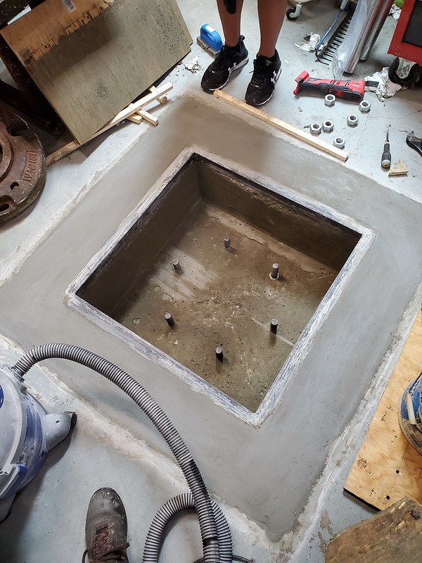
So back to the problem at hand, I did a post-mortem survey of what am I left to work with. Over 24” of level its out by about ½” of shim. Not ideal but definitely recoverable.

Brought the post in from the back shop where it had been hanging out for seemingly a few months. Last I touched it, was when I had welded on the cap. And that was winter!

And promptly dropped it when my hand slipped and I killed the 4 wheel dolly. If you recall it also claimed the life of an angle grinder….grr….The good news is that some old splintery plywood gave up and the casters aren’t damaged.

But I got it stood up so I can test the fit of the base into the pocket.

I could see from a tape-measure “survey” of the studs that the one in question was off by a bit, I needed just a little tweak to bring it over, out came the porta power and a block of aluminum to protect the thread.

You can see my first attempt with a softwood 2x4 didn’t work correctly….the base of the cylinder just punched a hole into it (!!) You can see the flat steel backer above…

First, armed with the forklift, I dispatched the 3/4" steel plate back outside...no more hauling that heavy sucker around with a hand truck!! To handle the column, I wrapped a 2” ratchet strap around the post with a couple of 2x4s trapped in opposition. I reversed one of the J-hooks that attaches to the steel ratchet body and also reversed the way the loose strap end fits in so it didn’t dig into the OD of the column. The j-hooks are connected with a trapezoidal link borrowed from another piece of rigging. This works but must be banjo-tight.

And, while several studs are piloted some are also off. I thought this could be an issue. I’m using 1-1/8” studs instead of the required 1” diameter, so the 1-1/4” thru-holes are kind of tight. I thought I had it solved in the form as I tested it but I think the dynamics of the pour got them off slightly.

Typical field-fix would be to break out the torch and “slot” the holes, but I didn’t want to go that route. Instead I pulled a 1-1/4” holesaw and a 1-1/2” holesaw piloted on the same arbor.

Like any holesawing operation thru metal, some chip-dropout holes are mandatory. My old holeshooter was getting *HOT* and so I let it rest by the fan while I drilled these holes with a cordless.

Eventually I got all 6 punched thru, holes deburred with a half-round file.

In my haste I killed some 1/8” pilot bits, leaning too hard on them while breaking out the bottom…this job was done late in the last day of a vacation, I got a late start as my neighbor had the orange forklift in his shop and was working that day, so I had to wait until he got home before I could start.

Success! I can go back to work knowing I accomplished something
One of my first send-cut-send.com projects was some laser cut washers for this project, they are ½” thick hot rolled. Something I could have done on the lathe but with a lot more time and prep. Instead I just designed it in CAD and sent off the .dxf file, wait a few days and voila! On my doorstep.


Now I’m onto aligning the column vertically. Starting with the rough measurement on the torpedo I’m off by about half a bubble.


Enter this tool of great sophistication, some steel flat counterweights, a notched piece of repurposed concrete form, and a plumb-bob. I read about this concept in the Gorbel manual awhile back, and it makes perfect sense, rather than relying on the eyeball accuracy of a 10-12” torpedo level, spread the error out across 7-8 feet with the plumb bob.

The bob…is a Starrett 177 which is no longer made, allegedly there is Hg = mercury in the tip of it…like any old Starrett tool it’s a supreme piece of craftsmanship. I always admire the neat way the stringline is quickly laced right to the centerline of the cap. The cap unscrews and extra string can be stored within the body.


So now the game is to iterate on measuring string position out from the OD of the tube, compare top and bottom measurements and shim in between until everything is measuring the same. Move 90 degrees and repeat, move back 90 degrees and check previous work as I was using 3 stacks of shims so there would be no rocking.
The question is where does one stop, this iteration could go on forever lol. I was satisfied with a deviation of 1/64” in the scale measurement over 8 feet. Should be less than 1/32” on the 12 foot crane arm. At the end I did go around and check the 180-degree opposite sides to verify they were equivalent.

I started with a 5/8” nominal block and I am using these Douglas Stamping shims, excellent to have, these are in 1.0, 0.5, and 0.25mm steps. More or less I think of my finest step as being 1/4mm or ~.010”. Various other pieces of steel flat made it into the mix, at the end it doesn’t matter much what is used. The shims just give an organized way of thinking about where to go next. I did end up using a piece of .004” shim stock to cut the last spacers. I think that level of detail is way beyond where a typical professional millwright contractor would go with this, being that I usually see stacks of flat washers on non-grouted cranes that bolt to the floor where I work.


With the bolts snugged tight on the shim stacks, everything verified one last time, the plumb bob can go wait for its next job. And I can goto the Home D for a bag of Quickcrete “precision” non-shrinking grout.

I’m going to use the “fluid” mix, ideally I want this to self-level under the large baseplate of the column and provide “perfect contact” with the unlevel concrete. In my case I don’t have to build a dam around the base, the pocket walls will suffice, and 1 bag of grout checked out to be sufficient volume. Even in the weakest state which I’m using its documents advertise a compressive strength of 5000 psi, which theoretically should exceed that of the 4000 psi concrete.

Preparing tools and materials….

And I’ve got a pail full of grout.

I will say I would have liked more of the “self leveling”….but I didn’t want to make a weak watery mix.

You might be able to barely make out my special installation tool which is a tig filler rod bent so that I could push grout from the outside in towards the center.

Instructions state to moist-cure the grout 3 days, so I filled a spray bottle and hit it morning and night. At first it seemed very thirsty and this went down day by day, not sure if that was related to the exothermic heat or environmental conditions, but I stopped spraying at day 5. I can’t water-spray the grout trapped under the base at any time, so I’m just relying on diffusion or wicking to get there.


Epilogue to this episode…everything went as planned here, no pitfalls to report other than a few broken drill bits. I’m pleased as I was able to “erase” the errors of my ways with the concrete pour. At this point it will only be known to us on the blog
Thanks again for following along!