Placeholder17
Well-known member
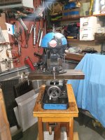
I finally got around to messing with the Benchmaster vertical mini knee mill I picked up 1.5 years ago.
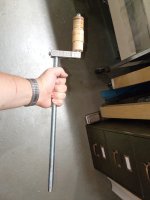
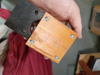
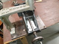
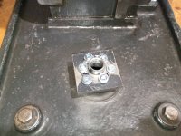
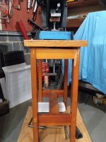
It is a variant advertised in the original catalogs as a "production" model, with a lead screw only in the Y direction and rack/pinion gears in the X and Z directions. The previous owner replaced the Y direction with a lead screw, but the Z direction was unchanged. Fortunately, the manufacturer used the same base casting across all models and so the casting already had a large hole where the Z lead screw bushing would have gone. I rigged up a vertical lead screw with a 5/8" coarse threaded rod and a screw mount nut, with a ball bearing at the top of the screw. The bearing sockets into a counterbore in a piece of wood screwed to a cast-iron plate which cantilevers from the casting that contains the rack arm bore.
This gave me more precise vertical travel, but I can only reach the crank below the base and stand by bending sideways, causing me to lose sight of the clamped work and cutter. So, I added a nut to the shaft just under the bearing, locked in place with a set screw. This can be turned by feel using a wrench while standing straight for fine adjustments to height.
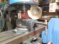
For measuring vertical travel, I made an adjustable support arm and clamp for a dial indicator cantilevering from a 3/8" rod that came with the machine, screwed into the base casting. I would have preferred to have the standard model with a lead screw and bevel gears for vertical travel, but this at least gives me precision, even if it's slower to adjust.
Regarding the disassembly of the spindle, I found a post on home machinist clarifying the correct procedure:
https://bbs.homeshopmachinist.net/forum/general/51599-my-benchmaster-mill-refurbishment-project
However, since forums and posts disappear eventually, I will give the steps I took here:
It is a variant advertised in the original catalogs as a "production" model, with a lead screw only in the Y direction and rack/pinion gears in the X and Z directions. The previous owner replaced the Y direction with a lead screw, but the Z direction was unchanged. Fortunately, the manufacturer used the same base casting across all models and so the casting already had a large hole where the Z lead screw bushing would have gone. I rigged up a vertical lead screw with a 5/8" coarse threaded rod and a screw mount nut, with a ball bearing at the top of the screw. The bearing sockets into a counterbore in a piece of wood screwed to a cast-iron plate which cantilevers from the casting that contains the rack arm bore.
This gave me more precise vertical travel, but I can only reach the crank below the base and stand by bending sideways, causing me to lose sight of the clamped work and cutter. So, I added a nut to the shaft just under the bearing, locked in place with a set screw. This can be turned by feel using a wrench while standing straight for fine adjustments to height.
For measuring vertical travel, I made an adjustable support arm and clamp for a dial indicator cantilevering from a 3/8" rod that came with the machine, screwed into the base casting. I would have preferred to have the standard model with a lead screw and bevel gears for vertical travel, but this at least gives me precision, even if it's slower to adjust.
Regarding the disassembly of the spindle, I found a post on home machinist clarifying the correct procedure:
https://bbs.homeshopmachinist.net/forum/general/51599-my-benchmaster-mill-refurbishment-project
However, since forums and posts disappear eventually, I will give the steps I took here:
- Unscrew pre-load collar at top of spindle
- Unscrew spindle pulley set screw. Pulley should be slip-fit on the spindle with roughly 1/2" of vertical travel.
- Hammer the spindle down with a wooden mallet (lightly) until the spindle moves down around 1/2" and thunks into the top of the lower bearing seal.
- Shim up the pulley and try to hammer out the woodruff key from the spindle shaft with a punch. In my case, the angle was too awkward and the key was to tight, so I had to leave the key in.
- Finish hammering the spindle down and out. In my case, I had to accept that the key punched through the upper felt seal of the lower bearing on the way down.
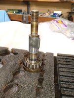
- The lower bearing will be press-fit on the spindle. The upper bearing will be flopping around loose in the upper bore.
- Spin the spindle arm upside down. Cut a 1.5" long x 1/4" wide piece of at least 1/8" thick steel. By hand, slide this piece into the upper bearing bore (now upside down), to bear on the inner race of the trapped bearing. A punch cannot reach through the hole cleanly to tap on the bearing itself because the seal diameter matches the inner race diameter. Now you can hammer on the center of the piece of steel with ease. The seal ahead of the bearing should come out with the bearing.
- In my case, I think the previous owner had already cleaned and repacked the bearings in the past, because although each was engraved 2/20/1952, both were full of perfectly wet and oily grease. Nonetheless, just to reestablish a firm relubrication date, I scrubbed them clean in acetone and repacked.
- Bearing Numbers:
Timken 09074 Tapered Roller Bearing
Timken 09194 Race
Timken 15118 Tapered Roller Bearing
Timken 15250 Race
The felt seals can be replaced with the following rubber lip seals:
SKF 10111 Seal
SKF 15160 Seal
SKF 7573 Seal
SKF 11878 Seal
Seal Notes:
10111 Top outer - is a direct replacement with no modifications needed
7573 Top inner - needs modification.
11878 Bottom inner - is slighty over sized on the OD but fits the bore without
problems and is installed from the outside.
15160 Bottom outer - is a direct replacement with no modifications needed
Attachments
-
 Production Model.png1.3 MB · Views: 21
 -
 IMG_20260716_075958480.jpg590.7 KB · Views: 21
 -
 IMG_20260716_154111749.jpg632.9 KB · Views: 15
 -
 IMG_20260716_165442020.jpg527.1 KB · Views: 19
 -
 IMG_20260717_122826743.jpg702.4 KB · Views: 19
 -
 IMG_20260717_122945668.jpg613.1 KB · Views: 22
 -
 IMG_20260717_152456427.jpg781.2 KB · Views: 18
 -
 IMG_20260717_152509766.jpg752 KB · Views: 18
 -
 IMG_20260717_152517795.jpg636.2 KB · Views: 18
 -
 IMG_20260719_191741341.jpg683.5 KB · Views: 19