Several people have asked questions about my custom lift install, so I’ll elaborate here. I must first preface this with the disclaimer that this is how I installed mine, which may or may not coincide with proper or approved methods. My goal with this install was to have no wires, hoses, or cables hanging over the lift, and I also wanted a fully clear floor with no bumps or seams in the concrete under the lift.
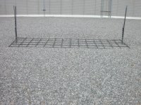
I had planned on having the System IA-10 from the very beginning of my shop build. While the shop was being built but before the concrete floor was poured, I determined the exact location for the lift. The shop floor was to be 6” thick but for added strength, I had the slab thickened to 12”at the lift location. I then had a grid of rebar installed based on the requirements found in the Mohawk installation manual. The installation manual had a requirement for an existing floor thickness with a minimum of 4.5” with no rebar required. If the floor didn’t meet those requirements or had cracks or other issues, the manual suggested a method to cut out a section of the floor and to pour a new section. The manual called for this new section to be 12” thick with the rebar grid. The additional concrete cost was minimal and the additional rebar was already onsite. The rebar was placed at a depth of about 6-7” from the top of the floor. That way, when I drilled the mounting holes in the concrete later, I would only be drilling 5-6” deep and would never have to worry about hitting the rebar.
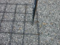
The right (passengers) side would be the column that had the hydraulic pump. In the pictures you can see the right side has 4 pipes and 1 piece of rebar coming up through the gravel base. These are located about 7-8” from the post base so that there are no cracks or other concrete inconsistencies closer than 6” from any of the wedge anchors (per the install manual). The 1” pvc conduit runs under the gravel base from the right post location to the back wall of the shop coming through the floor at the breaker panel location. This conduit will be used to bring power to the lift underground instead of from overhead. The 1/2” pvc conduit runs under the gravel base from the right column to the left column. This conduit will be used to get power to an outlet mounted on the left column. Then there are two stainless steel hydraulic lines that go under the ravel base from the right column to the left column. I sleeved these in black split loom for added mechanical protection. Lastly there is a piece of rebar used to tie all the conduits and hydraulic lines together and to keep them vertical and in place.
At the left column, location, there is the two hydraulic lines and 1/2” pvc conduit coming up through the gravel base from the right column. There is also an additional 1” PVC conduit coming up in this location. It goes under the gravel base to the back wall. It is used for running an air line through it so that I will have an air hose reel mounted on that column. After the lift was installed, I pulled flexible plastic air brake line (similar to pex, except designed and rated for air) through the 1” conduit.
I had planned on having the System IA-10 from the very beginning of my shop build. While the shop was being built but before the concrete floor was poured, I determined the exact location for the lift. The shop floor was to be 6” thick but for added strength, I had the slab thickened to 12”at the lift location. I then had a grid of rebar installed based on the requirements found in the Mohawk installation manual. The installation manual had a requirement for an existing floor thickness with a minimum of 4.5” with no rebar required. If the floor didn’t meet those requirements or had cracks or other issues, the manual suggested a method to cut out a section of the floor and to pour a new section. The manual called for this new section to be 12” thick with the rebar grid. The additional concrete cost was minimal and the additional rebar was already onsite. The rebar was placed at a depth of about 6-7” from the top of the floor. That way, when I drilled the mounting holes in the concrete later, I would only be drilling 5-6” deep and would never have to worry about hitting the rebar.
The right (passengers) side would be the column that had the hydraulic pump. In the pictures you can see the right side has 4 pipes and 1 piece of rebar coming up through the gravel base. These are located about 7-8” from the post base so that there are no cracks or other concrete inconsistencies closer than 6” from any of the wedge anchors (per the install manual). The 1” pvc conduit runs under the gravel base from the right post location to the back wall of the shop coming through the floor at the breaker panel location. This conduit will be used to bring power to the lift underground instead of from overhead. The 1/2” pvc conduit runs under the gravel base from the right column to the left column. This conduit will be used to get power to an outlet mounted on the left column. Then there are two stainless steel hydraulic lines that go under the ravel base from the right column to the left column. I sleeved these in black split loom for added mechanical protection. Lastly there is a piece of rebar used to tie all the conduits and hydraulic lines together and to keep them vertical and in place.
At the left column, location, there is the two hydraulic lines and 1/2” pvc conduit coming up through the gravel base from the right column. There is also an additional 1” PVC conduit coming up in this location. It goes under the gravel base to the back wall. It is used for running an air line through it so that I will have an air hose reel mounted on that column. After the lift was installed, I pulled flexible plastic air brake line (similar to pex, except designed and rated for air) through the 1” conduit.