To avoid these ads, REGISTER NOW!

Blackhawk S-4 Restoration

MBeaty

Well-known member
Joined
Feb 1, 2010
Messages
237
Location
Middle Tennessee
Background:

Yesterday I acquired a Blackhawk S-4 floor jack on Craigslist. All in all, it appears to be in working order and in quite great shape despite its age. For the most part, this restoration will focus on the mechanical aspects of the jack, as the final product will be one that I intend to use. Additionally, the jack is in pretty good cosmetic shape as it currently stands. I am sure that the more and more I tear into the project the larger it will become, but that is all part of the fun and learning process. This will be one of the first big projects that I have taken on so will be quite a trial by fire for me...the jack has at least double the years on it than I do, so there will be many questions along the way. Most likely this project will take a while as I will be changing jobs and moving soon, so it will get pushed to the back burner.

In talking with the seller of the jack, he gave me some of the history behind it. His father was a mechanic and general handyman and purchased the jack new, but the date was not known. Judging by the condition of the jack and the other objects in the shop, it was apparent that original owner had taken great pride of his equipment and maintained it properly.

I had just gotten back from being offshore for a few weeks when I found this jack on Craigslist and unfortunately much of the other tools and equipment had been sold including a mid 1930's Snap On tool chest.

Outside%20Saddle%20Down.jpghttp://4wdthunder.net/Matt/Outside Saddle Down.jpg

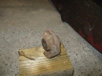
As you can see, the jack is quite clean already. Sharp eyes will notice the missing cap/lens on the jack’s headlight. This seems to be a problem that plaques most of these S-4 jacks. Also sometime over the years, the wiring for the headlight had been cut out of the jack.

Envelopes.jpghttp://4wdthunder.net/Matt/Envelopes.jpg

Another bonus with the jack was some original paperwork including an exploded view and parts list. Once I gain access to a nice scanner I will be sure to scan all the documents and post them here.

Diving In:

Hydraulically the jack did seem to function, though has a few little issues to it. One of the issues was that the saddle would not fall back down under its own weight/return springs after the jack was released. Also, from the instruction manual, Blackhawk states that the jack is equipped with an automatic two speed pump. This allows it to rise quickly until in contact with the load. This feature does not seem to be working as is.

Jack%20Bottom.jpg

This jack is quite a backbreaker to deal with so the first step is to remove the hydraulic unit from the rest of the jack to make it a much more manageable size and weight.

Unit%20Separated.jpg

4 bolts, 1 pin, and 1 cotter pin later, the hydraulic unit was removed from the rest of the jack. None of the bolts gave me much trouble to remove, but it is a little bit of a balancing act removing the last bolt once the entire weight of the hydraulic unit is on it. The linkages for the jack release contain a 2 piece “finger” that allows the rotation to be transferred, yet allows the hydraulic unit linkages to separate from the handle linkages with no fasteners.

The reservoir drain plug is located on the side of the hydraulic unit right behind the rear mounting bolt.

Unit%20Weight.jpg

Even by itself, the hydraulic unit minus fluid and a few bolts weighs in a little over 40 lbs which is heaver than my entire current jack. I am sure my wife would be thrilled to see her bathroom scale being used for this :)

I have not figured out what the plug on the top of the unit is for, but the exploded diagram refers to it as a "pipe plug."

With easy access to the drain plug, the old hydraulic fluid was drained and the cover plate on hydraulic unit was removed.

Gunk%20in%20Reservoir.jpg

As you can see, there was a considerable amount of gunk left behind once the fluid was drained. I am not quite sure how to best clean this mess up. I know that alcohol based cleaners need to be avoided in order to prevent damaging the seals in the jack. Also, I do not want to flush any of the junk further into the jack where it could cause damage. What do the experts recommend here to clean out the hydraulic unit?

Drained%20Fluid%20Color.jpg

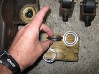
Here is a look at the color of the drained fluid. Also, you can see that the gasket for the top plate of the hydraulic unit will have to be replaced. It was actually not leaking at all, but when the cover was pulled off some of the cork from the gasket stuck to the body of the unit and other parts of it stuck to the cover plate. It is just a simple rectangle with 6 bolt holes, so I should be able to make a new gasket quite easily. The "tube" that you can see on the inside of the cover plate is for the headlight wiring.

Once I figure a way to clean out the hydraulic unit I will refill it with new oil and see if jack works any better, then diagnose whether it will need new seals or more in depth hydraulic work. Part of me is a little worried that with new oil that is less viscous, the seals may begin to leak.
 
Last edited:
To avoid these ads, REGISTER NOW!
OP
M

MBeaty

Well-known member
Joined
Feb 1, 2010
Messages
237
Location
Middle Tennessee
Getting Back at It

After a long break due to changing jobs and moving to a new state, I have finally made some more progress on the jack project.

Finishing where I left off, I had to make a new gasket for the reservoir cover. Initially I made one out of some gasket paper, but it would not seal completely. I think it was just too thin.

Gasket%20Paper%20Gasket.jpg

As you can see, the cover plate has 6 screws that hold it down. This secures it great along the sides, but the front and back of the plate have a decent span between the screws. With the thin paper gasket material, the oil would weep out of the front and back of the cover plate.
To fix this I bought some 1/16” thick cork gasket material and made a new gasket. I think I have read this tip here, but I cannot remember for sure so I will show it any way.

The cork is easy enough to cut with scissors or a razor blade, but cutting nice clean hole is difficult without some sort of punch. Rather than buying something, I just used an old 9mm casing because it was about the right size.

9mm%20Punch.jpg

First I used a normal ******* file to cut a bevel onto the "cutting edge"

9mm%20Punch%202.jpg

Then I punched out the primer so that I would have a way to remove the punch cuttings from the inside of the bullet casing.

Clean%20Hole.jpg

With a few light taps of a ball pein hammer, I was left with a nice clean hole. All in all it was an easy and best of all cheap solution.

Since the last update, I have actually used the jack quite a few times. It holds fine and does not leak, but something is not quite right in the valving of the jack. It was designed with a two speed pump, but mine appears to always bypass some of the fluid back into the reservoir, thus acting like it is stuck in the low pumping ratio. It is annoying, but it works for now until I can rebuild the hydraulic unit.

Another problem area I noticed while using the jack was the handle assembly. The control valve was hard to turn even when all the universal joints in the linkage were aligned to give minimal binding. Outside of this perfect alignment it was nearly impossible to turn. Also, the lever selector that allows the handle to be positioned in 1 of the 3 positions was quite sticky and difficult to operate.

The first step in diagnosing the problems in the handle was to remove the handle and disassemble it. In order to remove all of the internal mechanisms, the control knob had to be removed, but it had no visible fasteners on it. After rotating the knob I was able to align a hole in the knob with an internal spring loaded pin that holds the knob on.

Hidden%20Pin.jpg

After pressing the pin with a punch, the knob could be removed. Luckily due to the nasty dried up grease the spring and pin did not shoot out of place.

Pin%20Removed.jpg

Lock%20Face.jpg

As you can see in the pictures, there was a heavy coating of nasty dried up grease on all of the parts. This was nearly the consistency of clay, but much stickier. Needless to say this was leading to a lot of friction on the parts. I started trying to clean it with some biodegradable degreaser, but had no luck. Eventually the grease came right off after using kerosene as a degreaser.

Moving down from the control knob was a steel shaft with two universal joints at the pivot point.

Bend%20in%20Control%20Rod.jpg

As you can see, the shaft was bent, which was leading to some of the friction in the control knob. With a little persuasion in the vise, the handle was straightened quite easily. The universal joints are still quite sloppy though after the years of use. Eventually I will have to find a suitable replacement. As it is now, between both universal joints and the other various pinned connections, the control knob can rotate about 35-35 degrees before the slop is taken out of the system.

With all the grease cleaned off you can get a better idea how the safety lock in the handle knob functions.

Inside the top of the knob, there is a tab (12:00 in the picture) that mates with either of the two recesses in the mating component.

Cleaned%20Lock%20Assembly%202.jpg

Cleaned%20Lock%20Assembly.jpg


This allows the control knob to rotate freely and not release the jack unless the lock is locked into position. It is kind of a interesting feature, but is nothing I would ever need for home use, but I would still love to find a working key.

With all of the parts cleaned up and lubricated, the entire assembly works much better, but still has a few sloppy parts. Eventually I am going to have to machine a few new bushings to take up some of the slop and tidy the handle assembly up, but importantly it works as it is.

There will be more to come soon, but here is a little side note.

In my travels with moving I stumbled onto a really neat museum in Chattanooga Tn dedicated to Towing and Recovery. It was not large, but was full of neat old tow trucks and other automotive artifacts. Here were two mechanical floor jacks there predate mine by many years.

Old%20Walker.jpg

Cantilever%20Jack%202.jpg
 
Last edited:
OP
M

MBeaty

Well-known member
Joined
Feb 1, 2010
Messages
237
Location
Middle Tennessee
As I have said above, the owner of my jack still had the paperwork associated with it. I have scanned the operating instructions and a cutaway drawing/parts list for the jack. This was originally a folded up booklet, so the pages are a little mixed up when it was scanned as a flat sheet. The native size was about 11 x 17, so it can be printed that size and still look good. Both files are PDF's

Blackhawk S-4 Instructions Front

Blackhawk S-4 Instructions Rear
 

Griff93

Well-known member
Joined
Jul 25, 2009
Messages
1,121
Location
Huntsville, AL
You've made some good progress. Keep it up. I have an S4 as well that I'm going to redo at some point. My U joint it broken and Bull's is missing. I'm going to try making some of them. I need to buy a few more pieces of tooling first.
 
OP
M

MBeaty

Well-known member
Joined
Feb 1, 2010
Messages
237
Location
Middle Tennessee
Thanks for the comments guys!

Any Blackhawk items in the Chattanooga Museum?

Unfortunately no Blackhawk equipment, but there were several other pieces of old shop equipment such as a 1920's Weaver tire changing machine as well as some older diagnostic equipment. The real stars of the museum were the old tow trucks though. It was not a large museum, but I found it quite interesting it would recommend it to anyone traveling through the area.

Does your jack still have a spring for the handle mounted light switch?

Yes, it does appear to have all of the switch assembly in the handle. The wiring to the light and the actual lamp itself has all be removed but the switch was still stuffed in the handle.

Lamp%20Switch.jpg

Here are all the components that I found in the handle. The two leftmost components appear to be some sort of insulating rubber/plastic type material. The assembly would work just like a simple momentary contact switch.

Assembled%20Switch.jpg


Here are all the components assembled together in the cap.

Switch%20in%20Handle.jpg

Lastly, here is the the entire assembly put into the handle.

I can fix you up with a new key for your control knob, send me a PM if you are interested.

PM Sent

My U joint it broken and Bull's is missing. I'm going to try making some of them. I need to buy a few more pieces of tooling first.

I have actually considered making one as well, but I think I would take an easier route. If mine do get to the point of breaking, I think I would cut the old U joint off and find an impact swivel socket that is about the right size and weld it to the shaft. It would not look like the original equipment, but it would surely hold up to daily usage.

More updates coming soon.
 
Last edited:

smallcarguy

Well-known member
Joined
Jun 5, 2011
Messages
114
Location
Virginia
MBeaty said:
The cork is easy enough to cut with scissors or a razor blade, but cutting nice clean hole is difficult without some sort of punch. Rather than buying something, I just used an old 9mm casing because it was about the right size.

Now, if you had stood back 100 yards, and fired those 9mm holes in there, well, then.. that would be something...

Kidding of course. Nice idea on the hole punch... And great work on the jack...:beer:
 
OP
M

MBeaty

Well-known member
Joined
Feb 1, 2010
Messages
237
Location
Middle Tennessee
Reassembly of the Handle Assembly

After cleaning all of the dried up grease out of the components in the handle assembly it was time to put it all back together. Due to some of the interesting features on this jack, such as the 3 position handle adjustment and the release knob at the top of the handle, the handle assembly has many components.

Handle%20Assembly%20Laid%20Out.jpg


This picture gives a good overview of all of the components in the handle. The rod on the top and the components parallel with it all deal with the control know of the jack. The middle rod and components are the handle position adjustment. Lastly the bottom component is simply the handle. Interestingly, I think the handle was supposed to originally split into two pieces.

Position%20Handle.jpg


When I first got the jack, it was quite difficult to adjust the handle position. It seemed that no matter how hard I pulled on the release trigger, the position pin would not pull up high enough to adjust to the next hole. After cleaning and reassembling it all it turned out to be a very simple fix. At the top of the rod, above the trigger, you can see a round nut (looks more like a bushing in the picture.) This is an adjustment nut that has a slot in the top for a Phillips screwdriver. By simply tightening this down more, there is more preload put on spring that holds the position pin in place. With it cleaned, greased, and properly adjusted the position adjustment works quite easily now.

Welded%20Handle.jpg


The bottom of the handle does still have the bolts to hold it on, but it has been completely welded around. The paint color on the handle also seems to vary slightly from the rest of the jack. It makes me wonder if the entire handle tube was replaced at one point. Having it welded together is not a problem, but it does make reassembly a little more complex. Fishing the position release rod into the corresponding hole in the release pin it more challenging because it must be done from the top of the handle rather than from the bottom.

U%20Joints.jpg


The picture above shows the U joint setup. As you can see, with 2 U joints and the third telescoping slot and pin arrangement, it is difficult to keep slop out of the system. Eventually I will have to replace all of these components, but for the time being I will leave them be and just live with the slop.
 
OP
M

MBeaty

Well-known member
Joined
Feb 1, 2010
Messages
237
Location
Middle Tennessee
Castor Rebuilds

After getting the handle assembly back together I started on the front and rear casters of the jack. This seems to be a sore spot on many of these old Blackhawks and Walkers. Fortunately mine were in pretty good condition from only being in service at a home shop rather than a commercial operation.

Starting with the rear casters, observant eyes will notice that the previous owner had put a bolt through the top of the caster in order to keep some tension on the bearings as well as keeping the caster centered in the bearing assembly.

Side%20View%20User%20Mod.jpg

In this picture you can see the original screw (from the side of the caster ear) as well as the bolt through the top that the previous owner had installed.

Caster%20Parts%20Uncleaned.jpg

With the caster assembly taken out of the jack and disassembled you can see that all the parts are in fairly good condition. The axles for each of the caster wheels had some minor pitting, but were in good enough shape to clean up with a little sandpaper and reuse.

The casters on this jack seem to be in interesting design. The caster bearings have an integrated race in the caster ear of the jack frame. This bearing supports the weight of the jack plus its load and allows it to rotate easily, but due to the design, the bearing does not actually help to "locate" the caster. Instead the shaft on the caster yoke is inserted into a bore in the caster ear. This surface locates the caster and keeps it coaxial with the bearing.

Bearing%20Race%20in%20Jack%20Ear.jpg

Wear%20on%20Caster%20Shaft.jpg

Odd%20Bearing%20Fit.jpg

In the pictures above you can see the bearing race, which is in quite good condition, as well as the bore where the casters yoke inserts into the jack frame. As you can see in the picture this surface has been worn over the years and allows the casters to have some slop despite the bearing.
Looking at the bearing, it seems like the design did not spec the proper ID for the inner race of the bearing. As you can clearly see, it does not fit tightly around the caster yoke shaft, thus forcing a steel on steel contact surface on the shaft. On the right hand side of the shaft, you can see some wear marks. Also, you can see where the original caster retaining screw has worn the lip on the yokes axle.

Caster%20Bearing.jpg

Thanks to fellow GJ member Steve Bryant, I have received some exploded assembly diagrams of the jack. It is interesting to note that in the following image, the diagram show a cartridge style bearing in the jack. It makes me wonder if this was a design change during the manufacturing period. Either way the jack could benefit from a redesigned bearing design where the bearing would support the load of the jack and also prove a positive concentric relationship between the bore and the yoke axle.

Caster-Slop.gif

After cleaning, greasing, and reassembly, it is some side to side slop in the caster, but with the weight of the jack actually resting on the bearing it is hardly noticeable.

Front%20Bearing.jpg

The front wheels were much more straightforward. They are simply a needle bearing where the inner “race” is the front axle and the otter “race” is the ID of the wheel. All of these parts were in quite good condition, thanks in part to the front wheel having a grease zerk on them.

Bearing%20Needles.jpg

It is interesting that out of all of the bearing needles, they were in quite good condition except for 2 of them.

When I get access to a lathe I would like to turn down the rolling surfaces of the casters, but for now I just chucked them into a cordless drill and cleaned the surfaces with some sand paper. There is no way around the fact that this jack is quite heavy, but with freshly cleaned and greased wheels, it rolls much lighter than it originally did.
 
Last edited:

Bull

Super Moderator
Joined
Dec 12, 2005
Messages
16,189
Location
MA
How many ball bearings did you find in each rear caster? I removed mine today. One caster had 21 bearings in it, assuming I didn't lose any when it dropped down from the bore. The other had ZERO. I found 1/4" bearings for cheap on Amazon, so hopefully they will work. Not sure how well the one caster was working with zero balls in it.
 

Kazimodo

Member
Joined
Jun 17, 2013
Messages
9
How many ball bearings did you find in each rear caster? I removed mine today. One caster had 21 bearings in it, assuming I didn't lose any when it dropped down from the bore. The other had ZERO. I found 1/4" bearings for cheap on Amazon, so hopefully they will work. Not sure how well the one caster was working with zero balls in it.

Nice coincidence , also had one side full of balls ,
other side empty ......the ring that fits on the bottom was
worn out and smaller , I think I remember finding balls on the
floor 40 years ago ,while moving the jack around to help my father .
.
Anyway ,thanks Bull , for counting the 21 balls ,
I was going to get 60 , and put as many as I can on each side
.
OH and specially , Thanks to MBeaty for putting this
step by step together , very well made .
 
Last edited:

Bull

Super Moderator
Joined
Dec 12, 2005
Messages
16,189
Location
MA
Nice coincidence , also had one side full of balls ,
other side empty ......the ring that fits on the bottom was
worn out and smaller , I think I remember finding balls on the
floor 40 years ago ,while moving the jack around to help my father .
.
Anyway ,thanks Bull , for counting the 21 balls ,
I was going to get 60 , and put as many as I can on each side
.
OH and specially , Thanks to MBeaty for putting this
step by step together , very well made .

Hey, glad my counting helped; that's what this site is about.

I was amazed at how easy it was to find the correct bearings for the wheel, and at a very low cost.

My jack remains a decoration because of broken u-joints, but a fellow on here did have a thread about using 1/4 drive Craftsman universal joints and extensions to repair his jack. It's on my million-mile long to-do list.
 

Kazimodo

Member
Joined
Jun 17, 2013
Messages
9
Hey, glad my counting helped; that's what this site is about.

I was amazed at how easy it was to find the correct bearings for the wheel, and at a very low cost.

.

Bull, when you say , "amazed at how easy to find the correct bearing "
are you saying you actually found a place to get the lower part that
holds the ball bearings , I got 50 ball bearings ( 1/4 inch ) but
on one side ,the part that holds the bearings is smaller in diameter ,
it was grinded down over the years by the balls ,
I am trying to machine a big washer to put the piece in ,
and somehow give it more width ,but if that thing can be ordered
on the net , I would be happy to know where .
.
here are pictures of what i am working with .
And a couple of "teasers" to show you the 2 u-joints
as seen from underneath .
if you need to know actual lenght of the shaft
between the 2 u joint just ask .
Mike.
 

Attachments

  • under side castor bearing holders.jpg
    under side castor bearing holders.jpg
    143.9 KB · Views: 213
  • Side screw original.jpg
    Side screw original.jpg
    146.4 KB · Views: 182
  • U joints 1.jpg
    U joints 1.jpg
    139.1 KB · Views: 198
  • U joints 2.jpg
    U joints 2.jpg
    146.3 KB · Views: 185
  • New wheels.jpg
    New wheels.jpg
    147.7 KB · Views: 198
  • Old wheels.jpg
    Old wheels.jpg
    141.2 KB · Views: 177
  • Bearing holders.jpg
    Bearing holders.jpg
    149.7 KB · Views: 207

Bull

Super Moderator
Joined
Dec 12, 2005
Messages
16,189
Location
MA
Sorry to mislead you, I meant that it was so easy to find the ball bearings. They were right on Amazon and dirt cheap. That might not surprise anyone else, but I don't often find myself looking to replace miscellaneous old bearings like that.

The piece you need is S4. 155A-1, Rear Wheel Caster Bearing. The one place I have bought parts for an S4 before does not show any in stock. Most of these old parts are unobtanium in new condition these days. Ahh, to be a machinist.
 

Kazimodo

Member
Joined
Jun 17, 2013
Messages
9
No need to be sorry Bull ,
I also found the 1/4 inch ball bearings
over the counter they were 18 cents each :eyecrazy:
.
the S4 155A1 part number is nice to know ,
I also found that number in the files that MBeaty posted
but it is useless with new places that sell bearings ,
we need a modded Delorean to go back in 1955
to get that part , as you say , it is a job for a machinist.
 

Bull

Super Moderator
Joined
Dec 12, 2005
Messages
16,189
Location
MA
No need to be sorry Bull ,
I also found the 1/4 inch ball bearings
over the counter they were 18 cents each :eyecrazy:
.
the S4 155A1 part number is nice to know ,
I also found that number in the files that MBeaty posted
but it is useless with new places that sell bearings ,
we need a modded Delorean to go back in 1955
to get that part , as you say , it is a job for a machinist.

And you know, we do have machinists on this forum. Perhaps one could be hired to produce what you need by using the remaining, good bearing as a template?
 
To avoid these ads, REGISTER NOW!

Kazimodo

Member
Joined
Jun 17, 2013
Messages
9
I already have a machinist friend ,
he's the one who convinced me to redo the small
wheels in a newer technology product , It will take away from the
" antique" look , but the Nylatron is used in machining pulleys
for humongus cranes now days , Superior to metal , easier to
machine and lighter, I am using this Jack all the time ,
I want it to be functional , not just pretty.
.
so instead of bothering a member,
spending a lot on shipping both ways ,
I go over to my friend' s house , have a beer or two
give him the goodies , then we get to have a few more beers
when I go get the new goodies .
.
It's all good :drink:
 

Kazimodo

Member
Joined
Jun 17, 2013
Messages
9
Wheels are done , machinist friend to the rescue ,
the eroded bearing seat was smaller now , I tried to shave
some meat from a washer to sit the eroded seat in it ,
but my machinist friend made a duplicata of the intack one .
.
What a difference , I remember we used to drag
this 200 + pound monster as if it was on skis ,
( since 1972 ) now it glide arounds the garage floor ,
Fantastic , now on with the oil change
same oil since my Dad bought it used in 1972,
probably original oil from the 1950's .
.
Happy , Happy , Happy
 

Attachments

  • Big wheels.jpg
    Big wheels.jpg
    144 KB · Views: 230
  • Comparaison.jpg
    Comparaison.jpg
    145.7 KB · Views: 235
  • eroded bearing seat.jpg
    eroded bearing seat.jpg
    144.9 KB · Views: 225
  • new machined seat.jpg
    new machined seat.jpg
    134.1 KB · Views: 228
  • 20 ball bearing.jpg
    20 ball bearing.jpg
    146.7 KB · Views: 247
Last edited:

Bull

Super Moderator
Joined
Dec 12, 2005
Messages
16,189
Location
MA
Awesome progress. If your friend starts making new u-joints, let me know.
 

Gtobud

New member
Joined
Dec 24, 2013
Messages
1
Hey all! Newbie here excited to see this project. I have this exact same jack and didn't realize how old it was or that it had the battery operated headlight. Mine has the same issue with the release springs being unable to pull the lifting arm down without help. Have you found the problem? Mine will pull down under load but will otherwise stick until you jump on it or give it a sharp blow. I can't figure out if there's a mechanical bind at some of the pivots or if there's particulates or something impeding the fluid. I'm eager to learn fom your posts to get started. Thanks for posting the schematics!
 

Dave455

Well-known member
Joined
Mar 19, 2013
Messages
5,796
Location
Sussex, England
Those old Blackhawk jacks are just superb! Hope the resto goes well!

I would love one in my place, but few of those made it to the U.K.

Isn't it a shame, that in an age when we can do so much so easily, we can't make a relatively simple piece of equipment to the same standards that we used to!
 

469 runner

Well-known member
Joined
Jan 5, 2006
Messages
353
Location
North Carolina
I restored one of these a couple years ago. It needed a new release link and one new caster that I was able to find. I really enjoyed working on this, and now enjoy using it. A002.jpg

008.jpg great old jack.
 

Kazimodo

Member
Joined
Jun 17, 2013
Messages
9
Hey all! Newbie here excited to see this project. I have this exact same jack and didn't realize how old it was or that it had the battery operated headlight. Mine has the same issue with the release springs being unable to pull the lifting arm down without help. Have you found the problem? Mine will pull down under load but will otherwise stick until you jump on it or give it a sharp blow. I can't figure out if there's a mechanical bind at some of the pivots or if there's particulates or something impeding the fluid. I'm eager to learn fom your posts to get started. Thanks for posting the schematics!

Hi Gtobud , if you go to the first post in page one , look at the 3rd
picture , over and under the piston there are 2 springs , about
6-8 inches long ,5/8 inch big , mine as lost one , and I also have to
help it go down , would not be hard to find a screen door spring,
that can do the job for this , or any spring long enough .
.
If you have not already downloaded the 2 charts in post number 5
on the first page , get them while they are still up , it is priceless
for any S-4 owner , in the charts you will find the springs .
The drawings are of each end of the springs it is not
completely drawn in drawing .
In chart = part number 103 , pull spring , quantity 2 .
 
Last edited:

autobon7

Well-known member
Joined
Oct 27, 2010
Messages
730
Those old Blackhawk jacks are just superb! Hope the resto goes well!

I would love one in my place, but few of those made it to the U.K.

Isn't it a shame, that in an age when we can do so much so easily, we can't make a relatively simple piece of equipment to the same standards that we used to!

I could not agree more with your above statement in that today's world this fine piece will never be built again but on the other hand Asian factories can pump out thousands and thousands of cheap disposable POSs :dunno:

I have an old Weaver that needs some work but will keep it tucked away until the time comes. In the meantime I love to watch the progress of jacks like the one in this thread. Keep up the good work.
 

Hmaxims

New member
Joined
Oct 3, 2012
Messages
2
I know this is an older thread, but it keeps coming up when I search for parts. I have read this thread in its entirety (among others).

I bought one of these for $50 at a yard sale about 2 years ago but my sons were playing with it and while releasing it, they broke one of the universal joints underneath. I have seen seal kits and other parts - but it seems that there are several people that have had the same issue. For what I paid, it seems worth it to invest some more cash into it. Hell, I bought it to use it!

I found some U-joints online (in addition to the 1/4" Craftsman) that would suffice but the u-joint that is broken is the lower one that threads into a bushing on what I presume to be the oil reservoir. I am so nervous to dismantle this, cut the rod and try welding and screw it up!

Has anyone come up with any other solutions in the more recent past/meantime?
 

whateg01

Well-known member
Joined
Mar 13, 2006
Messages
11,183
Location
doo dah, kansas, usa
I hate reviving old threads, but some of these are exactly what I'm looking for.

I've finally started to look the one over that I bought for $70. It all works, but like so many others, the light lens is missing and the switch assembly is gone. I can remake all of this, or something that looks reasonably close, but how does the wire make it to the light? I haven't taken it all apart yet, so maybe it will be obvious then, but if I can figure it out ahead of time, that would be great.

Seems like I have seen some jacks without the light. Was this an option back then? If so, maybe a PO replaced the cover with one that had the light? Doubtful, but that would explain why I haven't even found a wire for the light.

Dave
 

Sweet Old Bill

Well-known member
Joined
Mar 20, 2009
Messages
362
Location
N. California
On mine the wire is run inside the handle and down to the body of the jack.

If the switch is missing, which it usually is, one can make a replacement switch from one of the free Harbor Freight flashlights.
 

whateg01

Well-known member
Joined
Mar 13, 2006
Messages
11,183
Location
doo dah, kansas, usa
Thanks Bill! I finally stumbled across a picture of a jack showing the wire running out the back of the cover. It made sense after I saw that. Whoever had this jack open last put the cover/light housing on backward so the hole wasn't at the backside near the handle. Guess I didn't put 2 and 2 together there.

That original circuit seems like it leaves a bit to be desired, but I guess it must work. I think I want to make a replacement that looks like the original, but uses an actual switch that is likely to be more reliable. Then I think I'll see if I can fit a LED in place of the original bulb and maybe one of those Harbor Freight flashlight battery packs in the handle. Seems like an interesting project that might work better and retain the OEM look.

I need to find somebody to measure the lens surface radius so I can machine one to use for a silicone mold. Then I want to cast one in urethane or epoxy. Seems there are a bunch of parts for these that are impossible to find and the lens is one of them. I kind of wish I had a junk jack laying around that I could make parts for. I really enjoy making parts to restore old things like this.

Dave
 

66 heavycruiser

New member
Joined
Mar 26, 2016
Messages
4
Location
South Jersey
Hi all,
New here, this is a great thread about an awesome Jack! I the middle of going through my S4. I have been using it for 20 years with no problem until I noticed a leak from the piston/ram. Turns out the packing or gland nut was cracked and popping out. Any idea where I could find one??? None of true online places have one (not surprised), but seems like something a machinist could make if I had to go that route. Any ideas?

Thanks,
Sean
 

whateg01

Well-known member
Joined
Mar 13, 2006
Messages
11,183
Location
doo dah, kansas, usa
... Any idea where I could find one??? None of true online places have one (not surprised), but seems like something a machinist could make if I had to go that route. Any ideas?

Thanks,
Sean

Try to find a parts jack somewhere or have somebody make one. I'm lucky that I have a machine shop in the garage, so if I ever need it, I can make one. Hopefully, it never comes to that!

Dave
 

CadiMan

Member
Joined
Aug 4, 2016
Messages
8
66 HeavyCruiser,

I don't know if you are still looking for the Gland nut on your Blackhawk S4. but just purchased a used hard part for my S4 from Lazzar's HCRC. You have to make it easy for them, so remove the pump cover (6 screws where the head light is located) and read the exact model number from the plate. and look up the drawing on http://www.hcrcnow.com/drawings/blackhawk. get the item number from the drawing and the part number from the list. Submit your request from their CONTACT page on the website http://www.hcrcnow.com/contact. Not Cheep but original.

Sincerely, CadiMan
 

Tarl Cabot

New member
Joined
Aug 11, 2017
Messages
2
Location
Bowling Green, KY
Hello. I just registered for this site and have found this forum on the Blackhawk S4 to be very useful. I have an S4 that I rebuilt at the hydraulic repair business I worked at back in '91 or '92. I just got it back and I want to repaint it in its original colors. I did not remember about the pin that holds the top release knob in place. Thank you for reminding me about it. I was trying to remove the handle this afternoon and couldn't understand why I couldn't separate it for the handle tube! Very nice pictures and a lot of good info. Thank you.
 

dayradebaugh

Member
Joined
Jul 10, 2018
Messages
24
Location
KS
A newbie here in KS just bought a Blackhawk S4 DELUXE (got the headlight) for $30!!. It's all frozen up with sludge, but I took the power unit out. I had my hydraulics shop look at it. They've got $90 in it, and say it needs a new kit for $180, plus another $180 to put it back together, putting me at $450 repair.

Can a garage monkey like me tackle this job? Is there a good place to get a cheaper kit? I've rebuilt a jack before.

Thanks
 

Kazimodo

Member
Joined
Jun 17, 2013
Messages
9
I would say they are robbing you , but , nobody works for free , you elected not to get dirty so it will cost you , as far as a kit for $180 , there are no more parts in the market for the s4 , you are probably paying for research time , cork gasket sheets at auto part can't be that expensive , you would need many many rags to clean the interior of the " pump assembly " good luck .if it is any consolation , once it is restored you can use it for 50 years without any maintenance , I know that because my S4 has never been opened since over 50 years , it belonged to my father and I know he does not maintain anything until it actually breaks , the insides of my pump must look terrible , but it still works and lifts my 6500 pound pick-up and does not leak one drop .
 
Last edited:
To avoid these ads, REGISTER NOW!
Top Bottom