
You are using an out of date browser. It may not display this or other websites correctly.
You should upgrade or use an alternative browser.
You should upgrade or use an alternative browser.
let's see your craftsman block grinders
- Thread starter emeraldcoupe
- Start date


badgcoupe
Well-known member
Sweet score on that 3/4 with the stand! Its in great condition! You ****.
balane
Well-known member
Here's my two. I'll get around to restoring them sometime but I had to put them into service right after I got them. The 1/2 HP was $25 and the 1/3 HP was $2. Yes, $2 at a garage sale and it works great, they both work great. Powerful and quiet. I use them every day.
/
/
Attachments

ShadowRuleZ
Well-known member
Here's one I found on Craigslist last week for $60. - beginners luck. I didn't know anything about Craftsman block grinders until I joined this site recently. It's an 8", 3/4 HP commercial model with stand, #397-19451. It's only missing one eye shield and it runs smooth and quiet. It needs a new wire wheel and I'm shopping for a medium grit white grinding wheel.
I'd have a hard time saying no to a 3/4 horse one. Especially with the stand!
badgcoupe
Well-known member
Could I ask you all to show me how you are mounting the wheels on your block grinders? I can mount grinding wheels just fine but with wire wheels(as I've learned in another post) I seem to be missing bushings/washers.
Thanks!
Thanks!
torqueman2002
Well-known member
I'll go get a picture between innings for ya.
Nice colors!
I don't know how I keep missing the new posts in this thread, they're not showing up when I use the 'New Posts' button.
Nice colors!
I don't know how I keep missing the new posts in this thread, they're not showing up when I use the 'New Posts' button.
torqueman2002
Well-known member
Here's my two. I'll get around to restoring them sometime but I had to put them into service right after I got them. The 1/2 HP was $25 and the 1/3 HP was $2. Yes, $2 at a garage sale and it works great, they both work great. Powerful and quiet. I use them every day.
/
Nice vintage CM workshop there.
torqueman2002
Well-known member
Here's a 3/4HP with wire wheels. I can eMail higher res. pics.
You may want to add washers to 'shim' the wheel into the center of the wheel guard, like I had to.


You may want to add washers to 'shim' the wheel into the center of the wheel guard, like I had to.
Last edited:
cmandp
Well-known member
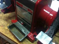
Just received in the mail today.


Came with the original manual with the sales receipt stapled to the back page, so I know when it was bought, who bought it and where; that info seems pretty cool to me. First thing I did was make sure it was wired for 110 and it was. Gave the spindle a spin to see if anything was obviously wrong with the bearings. Seem at least useable, but I'm no expert. Plugged it in and flipped the switch and it began to vibrate from the mistreated and out of balance wheels. Scared me a bit when it started to move around lol Taking the wheels off revealed what I suspect to be the original sears wheels.
The plan right now is to go through and check it out, clean it up and just get it working 100%.
Came with the original manual with the sales receipt stapled to the back page, so I know when it was bought, who bought it and where; that info seems pretty cool to me. First thing I did was make sure it was wired for 110 and it was. Gave the spindle a spin to see if anything was obviously wrong with the bearings. Seem at least useable, but I'm no expert. Plugged it in and flipped the switch and it began to vibrate from the mistreated and out of balance wheels. Scared me a bit when it started to move around lol
Taking the wheels off revealed what I suspect to be the original sears wheels. The plan right now is to go through and check it out, clean it up and just get it working 100%.

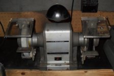
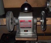
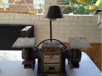
I went and did some electrical work at an old hospital that was being torn down. As I was walking through the different parts of it checking that all the electrical equipment was dead, I walked through the old powerhouse located at the rear of the hospital. Most of all the good stuff had been snagged by the crew doing the asbestos abatement, but this grinder was sitting there bolted to the floor. I didn't know anything about grinders really, but needed one at the house so I asked the site supervisor if I could snag it. I unbolted it and brought it home, started doing some research, and discovered what a gem I had found.
I haven't started any resto work on it yet, but I did fire it up, and she purrs like a lion. It's missing one rest, and the light shield/shade. Everything else is there. I think I will replace the cord though. I think a big reason it was still sitting there was that most the abatement guys aren't electrically minded, and saw the plug had 'funny sideways prongs' so they left it alone.
I read a lot on here about the different numbers, and how the 397 series was the most coveted. The sticker on mine was really faded so I wasn't sure. I took a bunch of pictures of the sticker up close, opened them up in Gimp and started playing around with the contrast and brightness until I could start to make out the lettering. It's a 397...
Incidentally, the red cabinets in the background were also taken from one of the hospital break rooms. Heavy duty hospital grade cabinets, of the metal variety. They're hanging in my garage now.
ShadowRuleZ
Well-known member
Awesome one horse grinder!
Kaervak
Well-known member
Awesome one horse grinder!
Not only that, it has the proper stand too. Therefore, you ****!

a guy has this one available local, does it say 2HP on it, did they make a 2HP Craftsman? He is asking $80, what do y'all think?
I dont think so. Its looks like a Briggs and Stratton sticker someone put on top of it. I dont think I would pay $80 for it in that condition. If you could get it for $40 or under then I would probably take it.
87Pomona
Well-known member
Just got done with my 1/3 HP grinder this morning
Colors are Colonial Red and Hammered Dark Bronze
Before

After


Colors are Colonial Red and Hammered Dark Bronze
Before
After
Last edited:
Rusty Musket
Well-known member
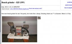
This just popped on my local Craigslist. I don't need another grinder but you guys sure have done some beautiful restorations.
http://portland.craigslist.org/wsc/tls/3380754413.html
http://portland.craigslist.org/wsc/tls/3380754413.html
Attachments
87Pomona
Well-known member
This just popped on my local Craigslist. I don't need another grinder but you guys sure have done some beautiful restorations.
http://portland.craigslist.org/wsc/tls/3380754413.html
If that was local to me I would ****** that up real quick!
Teter09
Well-known member
Here are my recent aquisitions....
3/4 HP from CL for $60....
View media item 25575
1/3 HP from CL for $30...(shields are on the workbench and complete)
View media item 25577
Does anyone have files for the 3/4 HP label that I can use to reprint mine? Torqueman is looking, but wasn't sure if he had them. Here are shots of the label, hopefully someone here has the same design....
View media item 25578
View media item 25576
ShadowRuleZ
Well-known member
I like those craftsman grinder stands, wish one of mine came with one.
torqueman2002
Well-known member
Could I ask you all to show me how you are mounting the wheels on your block grinders? I can mount grinding wheels just fine but with wire wheels(as I've learned in another post) I seem to be missing bushings/washers.
Thanks!
Another bit of info on the wwheels.
http://tinyurl.com/CM-Grinder-Wire-Wheels
torqueman2002
Well-known member
Here are my recent aquisitions....
3/4 HP from CL for $60....
1/3 HP from CL for $30...(shields are on the workbench and complete)
Does anyone have files for the 3/4 HP label that I can use to reprint mine? Torqueman is looking, but wasn't sure if he had them. Here are shots of the label, hopefully someone here has the same design....
Teter09 - take a look at the link posted in #103; imbedded in that link are links to the label files (Reply #7 & 19).
I hope that helps, I'm still looking for the files I used to scale it in Acrobat and then used a HP Officejet J4680 with Kodak photo paper to print it.
Nice going on those grinder rescues!
Check your messages, BTW.
Mike
Last edited:
torqueman2002
Well-known member
Here is mine, belonged to my grandfather.
Nice!

I've got a couple of CM wrenches and a 1/2" breaker bar from my grandfather. They're retired, but the grinders have lots of life left in them.
JASTECH
Well-known member
I am still in need of a 3/4 - 1hp block grinder. A GJ member located and now has in his garage a 6" Block grinder, Thank you so much as you know!
So please PM me if you locate a 8" block with tool rest and guards. Thanks, JASTECH & Son
So please PM me if you locate a 8" block with tool rest and guards. Thanks, JASTECH & Son
Teter09
Well-known member
Teter09 - take a look at the link posted in #103; imbedded in that link are links to the label files (Reply #7 & 19).
I hope that helps, I'm still looking for the files I used to scale it in Acrobat and then used a HP Officejet J4680 with Kodak photo paper to print it.
Nice going on those grinder rescues!
Check your messages, BTW.
Mike
Thanks Torqueman! Your email had what I needed. Thankfully I have someone with Photoshop who can easily swap the Serial Number for me!
Now I'm on to try to find one for the 1/3 HP I have!
Any experience with an alternate location for a model number? My front label (as the pictures show) is 100% gone. I'd worry about getting replacement parts (quench tray) based on an assumed model # based on looks alone.
Can anyone tell me what the case is made of? I don't have a sandblaster, nor anyone I know who has one, I was wondering if they could be popped in an electrolysis tank?
I'm guessing the center metal portion that looks stainless or galvanized probably can't, but I think I can clean that up with a sanding and some evaporust since there aren't too many hard to reach corners.
I'd also appreciate tips for cleaning up the eye shields. Mine aren't the nice metal ones, mine are all formed plastic which has yellowed....yuck!
Last edited:
torqueman2002
Well-known member
Thanks Torqueman! Your email had what I needed. Thankfully I have someone with Photoshop who can easily swap the Serial Number for me!
Now I'm on to try to find one for the 1/3 HP I have!
Any experience with an alternate location for a model number? My front label (as the pictures show) is 100% gone. I'd worry about getting replacement parts (quench tray) based on an assumed model # based on looks alone.
Can anyone tell me what the case is made of? I don't have a sandblaster, nor anyone I know who has one, I was wondering if they could be popped in an electrolysis tank?
I'm guessing the center metal portion that looks stainless or galvanized probably can't, but I think I can clean that up with a sanding and some evaporust since there aren't too many hard to reach corners.
I'd also appreciate tips for cleaning up the eye shields. Mine aren't the nice metal ones, mine are all formed plastic which has yellowed....yuck!
Take a look at the 1/4 & 1/3 HP ones in Reply #26. here --> http://tinyurl.com/CM-Block-Labels I no longer have the 1/4 HP one, but I can take a hi-res pick of the 1/3 HP one.
Sanding and evaporust should get you ready for priming and painting; I don't know about electrolysis. My 1/3 HP one is cast iron, but it is a Model 115; your 1/3 HP looks like it could be a Model 297 or 397. My 297 and 397s look like cast aluminum.
How about 3M's Headlight cleaner for the eye shields?
Good luck. BTW, the above link has a lot of good information and links to sites about these CM Block Grinders.
ShadowRuleZ
Well-known member
Here's a picture of my 1/3 horse label from a few pages ago, I could get a better picture if you needed it.

Teter09
Well-known member
Thanks shadow, that is exactly what my label should look like. I can make out the model and design numbers, but the rest is really faded. I notice there is no serial number, which is odd.
Headlight restorer, now why didn't I think of that? Especially since I just cleaned my headlights only 2 weeks ago! Probably have to get a few buffing pads for the dremel for the tight corners and spaces, but easy enough.
The 1/3 I'm restoring for dad for Christmas, and those eye shields have cracked plexiglass but I can replace that easy enough.
What wire wheels are people using when they clean em up that way? I was thinking a medium or fine brass wheel, just to be safe.
Richard D
Well-known member
I have four of these, not sure what H.P. they all are. The only one I paid more than $20-$30 is still unused in the box, I believe 1977.
Couple questions. I put wire wheels on one; how do you hold the shaft to tighten the nuts?
One that has grinding wheels, bogs down very easily. I am dumb about electrical stuff. Would that be caused by brushes, capacitors, resistors, transistors, flux capactor(see where I'm going with this-clueless)or maybe just dirty in there? Can someone take one of these things apart and describe how they work/how to fix common ailments?
torqueman2002
Well-known member
I have four of these, not sure what H.P. they all are. The only one I paid more than $20-$30 is still unused in the box, I believe 1977. Sweet.
Couple questions. I put wire wheels on one; how do you hold the shaft to tighten the nuts? Use a jam-nut to keep the the shaft from moving. Of course they have both right and left hand threads for the different ends.
One that has grinding wheels, bogs down very easily. What HP is the grinder? I have a 1/2 & 3/4 HP that do not bog down. I am dumb about electrical stuff. Would that be caused by brushes, capacitors, resistors, transistors, flux capactor(see where I'm going with this-clueless)or maybe just dirty in there? Can someone take one of these things apart and describe how they work/how to fix common ailments?

See my reply in Blue, above.
Richard D
Well-known member
"Use a jam-nut to keep the the shaft from moving. Of course they have both right and left hand threads for the different ends."
So, I could tighten two nuts against each other on the left side of the spindle, then mount the wheel on the right side. Then do the opposite on the other side. I don't think there will be enough shaft left protruding outboard of the wheel for the jam nuts. I'll have to look when I get home.
"What HP is the grinder? I have a 1/2 & 3/4 HP that do not bog down."
Not sure of the H.P., but even a 1/3 H.P. should do SOMETHING. It bogs down sharpening a soapstone.
Couple questions. I put wire wheels on one; how do you hold the shaft to tighten the nuts?
I actually use a low-power electric impact. The shaft still spins, but the impacting force turns the nut more quickly than the shaft if you hit it in short bursts, same for undoing it.
One that has grinding wheels, bogs down very easily. I am dumb about electrical stuff.
1/4 should bog a little under load. 1/3 should not unless you're really going to town on a coarse wheel, which would suggest one of two things. Either you're getting poor power to the stator, or you're losing a lot of your motor's energy in bad bearings. Depending on how old the unit is, replacing the capacitor and bearings will make the machine like new.
Capacitors, get an american made one from either Aerovox, Am-Rad, or Mallory. Mallory isn't in the game anymore but it's really easy to find NOS. You can order direct from Am-Rad and Aerovox has distributors everywhere but their CSRs have their heads up their asses.
Bearings there are three good options, shown in order of goodness here: German made *** (rofl) bearings, japanese made bearings of any brand, specifically Nachi (but they're all good), or argentinian made SKFs that can be picked up at your local bearing supply.
Can someone take one of these things apart and describe how they work/how to fix common ailments?
There isn't a whole lot to a grinder, I'll break it down here. What you have is a ultra-typical electric motor, which is a round stator with several yards of wire wound circularly around it which creates a rotating electromagnetic field when turned on and an armature (or "rotor"), which is a magnetic metal barrel that sits exactly in the center of the stator with a tiny few mm clearance all the way around. When the stator creates its spinning field, the armature "chases" the field in a circular motion trying to connect electromagnetically. Since it is always held away from the surface of the stator by a few millimeters, it never connects and just continues to spin and spin and spin as long as the stator has power, forever locked in a perpetual chase game of electromagnetic cat and mouse.
The armature is held in place through the center of ball bearings which keep the armature exactly in place never touching the stator, and allow the whole works to spin. Wheels and brushes are attached to the end of the spindle (the rod that runs through the armature and bearings) the take perpendicular-advantage of the spinning motion.
So here's, literally, all the parts of a grinder:
1) Stator
2) Rotor
3) Capacitor
4) Switch
5) Bearings
6) Body castings.
Of those pieces, there's only a few things that can go wrong and they all have a protocol for fixing.
1) Stator: wiring can break, corrode, or just generally fail. This is a death sentence for most any grinder worth less than $1000 because a full rewiring and rebuild is required and isn't cheap. This type of failure is extremely, extremely rare (like once every 100 years rare for the good brands). Symptoms: grinder doesn't work at all. Sometimes smoking from motor.
2) Your capacitor can blow. This is mega common, and extremely easy to fix. Capacitors are under $10 and can be installed with nothing more than a crimper and a screwdriver. Symptoms: Low power output, no power output, buzzing, humming, or smoking from base.
3) Your switch can fail. Buy a new one. Somewhat rare occurrence. Symptoms: low or no power response.
4) Your bearings can fail. Buy new ones for less than $10 each. Somewhat rare but totally plausible. Symptoms: Excessive heat at the spindle, excessive noise at the spindle.
5) You can get **** build up in the airspace between the rotor and stator. Corrosion or dust or grease or **** or god knows what get get inside cheaper grinders and degrade the function of the armature by creating friction. Symptoms: Excessive heat at the motor. Excessive noise at the motor.
Boom. Benchgrinder clinic 101. It really is that easy. There's like 6 parts in total, only 4 of which can fail, and all can be fixed. It's literally so simple a child could work on one with proper pictures and guidance. Here's some photos from a recent resto of mine.
Stator with armature inside. Visible is the wiring of the stator, the armature spindle, and bearings.
<a href="http://imgur.com/Atovj"><img src="http://i.imgur.com/Atovj.jpg" title="Hosted by imgur.com" alt="" /></a>
Close-up of armature within stator:
<a href="http://imgur.com/4Isiv"><img src="http://i.imgur.com/4Isiv.jpg?1" title="Hosted by imgur.com" alt="" /></a>
Stator with armature removed:
<a href="http://imgur.com/Al7Xj"><img src="http://i.imgur.com/Al7Xj.jpg?1" title="Hosted by imgur.com" alt="" /></a>
Armature with spindle and bearings:
<a href="http://imgur.com/lIqar"><img src="http://i.imgur.com/lIqar.jpg?1" title="Hosted by imgur.com" alt="" /></a>
Richard D
Well-known member
You had me at "It's literally so simple a child could work on one." Sounds like the capacitor is bad. I'll take the little ******* apart and replace it. So where is this "capacitor" you speak of? Got a picture? Is that what's in the lump on the side of a common electric motor?
Maybe I should mill some flats for a wrench before re-assembling?
Maybe I should mill some flats for a wrench before re-assembling?
So where is this "capacitor" you speak of? Got a picture? Is that what's in the lump on the side of a common electric motor?
The capacitor is traditionally in the base. It's a silver aluminum or shiny steel cylinder with a bunch of wires connected to two ports on the top of it.
I don't have a picture of my under-base restoration, but here's what my baldor looked like before I disassembled it:
<a href="http://imgur.com/Ce8Kx"><img src="http://i.imgur.com/Ce8Kx.jpg" title="Hosted by imgur.com" alt="" /></a>
That cylinder on the bottom is the cap. Here's a couple pictures of what my old and new caps looked like:
<a href="http://imgur.com/mDgl4"><img src="http://i.imgur.com/mDgl4.jpg" title="Hosted by imgur.com" alt="" /></a>You can see the old cap there in the center.
<a href="http://imgur.com/kNI3e"><img src="http://i.imgur.com/kNI3e.jpg" title="Hosted by imgur.com" alt="" /></a>New cap there on top with the bracket attached.
You don't even have to
. Typically you can just tip the little ******* over and work from right underneath it.take the little ******* apart
We're talking blocks, so maybe they're different. Someone who has one can chime in.
torqueman2002
Well-known member
Good info. ^^
Yours may not have a cap. Of the several I have opened up, only this pre-block CM grinder (Model 115) had a start-cap.
See this link for start-capacitor start-up switch found on early CM grinders.
http://tinyurl.com/CM-Brown-Grinder
If there isn't enough room for a jam nut, first remove the one end's nut and stone. I have found I can get 1 or the other end off. This will provide enough thread for 2 nuts, and allow the removal of the other end.
One note of caution, never stand in front of a grinding stone while starting up a grinder; in case the stone is damaged and flies apart.
To check a stone, refer to the link in my previous posts for a good source of additional information.
I wouldn't trust myself to use an impact on a grinder, too easy to over do it.
When reinstalling, take care to not over tighten. You want to snug up the stones/wheels. The rotation of the arbor and right/left hand threads will keep them from walking off.
Last edited:
cmandp
Well-known member
Interesting, my 397.19440 has a cap which I assume is for starting.Yours may not have a cap. Of the several I have opened up, only this pre-block CM grinder (Model 115) had a start-cap.

torqueman2002
Well-known member
Southern -- what I recall from the links, readings, and posts of others; is the paper label on the stones is to cushion the stone wheel as it is held by the cupped flanges. The paper distributes the clamping and turning forces on the hard but brittle stone wheel.
Over tightening and /or striking a stone may cause it to crack.
I don't mean to come off sounding like an expert; rather, I'm sharing some bits of knowledge picked up from other more knowledgeable and expert machinists.
I am not a machinist.
If you want more info. follow the links in my other posts; there are a number of resources I've found helpful rebuilding these handy machines we call 'block' grinders.