To avoid these ads, REGISTER NOW!

Between 265 & 485 SQ/FT The 12-Gauge Garage

Workspaces sized between 265 and 485 squarefeet.
Joined
Apr 29, 2012
Messages
14
Location
Costa Mesa, CA
if you made your diagonal brace into an X brace i bet it would have saved the uprights in this case. as always nice car and space.

Perhaps if they were rigid braces. An additional cable mirroring the existing would have failed into compression in this situation. Since cable stays only work in tension the failure would have occurred anyway since the upright buckled in the middle.
 
Last edited:
To avoid these ads, REGISTER NOW!

Outlawmws

Well-known member
Joined
Aug 9, 2011
Messages
39,109
Location
The Badlands
Perhaps if they were rigid braces. An additional cable mirroring the existing would have failed into compression in this situation. Since cable stays only work in tension the failure would have occurred anyway since the upright buckled in the middle.

The upright did not "buckle" in the middle, they unloaded sideways. whether the uprights would support the down force if kept vertical is a question for after they are stabilized for side load. The down force simply providing the added load to the side forces.

It was a rod if you looked closely, but whether it is cable or a "rigid" rod, you need an "X" to stabilize, and yes, two crisscrossed cables will work as when one is in "compression" (you can't compress load a cable) the other is in tension.
 

DocRocket

Well-known member
Joined
Feb 24, 2011
Messages
278
The upright did not "buckle" in the middle, they unloaded sideways. whether the uprights would support the down force if kept vertical is a question for after they are stabilized for side load. The down force simply providing the added load to the side forces.

It was a rod if you looked closely, but whether it is cable or a "rigid" rod, you need an "X" to stabilize, and yes, two crisscrossed cables will work as when one is in "compression" (you can't compress load a cable) the other is in tension.

I think, from the shape in the shadows, that the supports were on the edge of buckling and the side force provided the impetus to cause buckling. If the struts did, in fact buckle, that would keep the two cables/rods from holding them straight in the side force, as one diagonal could shrink, without extending the other, due to the effective shortening of the uprights. I would stand by adding stiffness to the forward part of the upright. However, I would also recommend the diagonal cables/rods being run to both uprights, not just one. I suspect that the wing, at that speed is creating about 200+ lbs of downforce (maybe more, depending on the airfoil, angle of attack, how much down flow is generated by the "fastback" of the Porsche, etc). At that point, with the thin supports, any wiggle/sideforce (brought about in this case by the centrifugal force of turning at 130 mph), is going to cause the support to no longer be in pure compression, so it has a bending moment and no real resistance to it, so it bends. The rod, I suspect, kept it close and helped produce the "S" curve shape the uprights took on, instead of allowing them to simply fold over. Probably the rod preserved the rear lid, but I suspect that in the neighborhood of 1000psi of compressive stress was in the front upright (about a 1/8" x 1 " section). Since the moment of inertia for lateral displacement would be about 0.00016 in^4, there would only need to be a very small lateral motion to cause the upright to buckle completely. If the front of the upright was supported with an additional thickness of aluminum on each side, the MOI would increase by a factor of 27, and the compressive stress would drop by a factor of 3, which should push that failure condition out to 9x the speed. The extra thickness would not be required at the rear, as that is only countering the pitching moment of the airfoil, not carrying the "lift" force, but should be in compression also (with about 10%, or less, of the load).
 

dwp99

Well-known member
Joined
Apr 18, 2012
Messages
167
Location
West Coast of Florida
I'm no scientist, physicist, engineer or mathematician but I have an opinion and an idea. You can clearly see the wobble in the wing as the car approaches the turn then the wing slams hard to the left and stops. That's when it comes against the diagonal brace. I'm assuming that the metal tabs at the end of the wing acted as rudders causing the wing to move to the left along with some centrifugal or G force . As the car exits the turn and the "rudders" steer the wing back to the right, or the pressure is released and it goes back. The wing goes too far to the right as you can see. The support attachment points are not able to remain parallel with each other and the supports buckle under the pressure of the down force.

Why couldn't the supports be made out of two pieces of aluminum per side? Instead of cutting out the material from inside to lighten it up, cut 3 large circles . Roll the edges inward on the circles so that there would be a 1/4" gap between the two pieces when held together. Tig weld around the circles, insert a 1/4" x 1" filler on the top and bottom, weld that in and use it to attach the supports to the wing and car. It would keep the support from crushing when the bolts were tightened. Then pinch the leading and trailing edge together and tig weld the full length. I know that it will double the weight of the supports but it sure would stiffen them up. Then add the diagonal brace.
 

Zeke

Well-known member
Joined
Aug 13, 2009
Messages
17,176
Location
Long Beach CA, the sewer by the sea.
Well. any of us that aren't ME's are really guessing here. So my guess is that the alloy is too soft. Sure, other design improvements will all help, but a harder alloy would snap before bending.

Now I realize that what happened here prevented any further mishaps like the wing detaching and hitting another car. So, recommending a different alloy goes along with recommending further stress analysis of the part.

I agree that a more 3 dimensional part would provide better aero, but Jack is working within the capabilities of his shop. So, the fabrication process is probably limited to the router and saws.

If I were doing this, I would explore carbon fiber honeycomb. Easy to cut but then it has the open edge. I would treat that with some strand and resin and then hand shape to a nice edge. The ultimate goal would be to eliminate the brace. That has to be prone to harmonics and flutter. Any drag added by thicker uprights would likely be cancelled by no brace.

Cross braces is going the wrong way, IMHO. But, I'm a big guesser, not an ME. Who knows, someone well versed in this application might even find cause to mount these uprights in or out a degree from in line with the direction of travel.

This is next for JO's 12 Ga Garage:

<iframe width="420" height="315" src="http://www.youtube.com/embed/kFGbeLy7aEM" frameborder="0" allowfullscreen></iframe>

 
OP
J

Jack Olsen

Super Moderator
Staff member
Joined
Mar 22, 2009
Messages
6,678
Location
Los Angeles
Poor Man's Hazet Assistent (call it an Ikea-zet Assistånt?)

First off, I understand that there's really no comparison between an Ikea cart and a Hazet Assistent tool cart. The Hazet folds down into a small, secure box. It's got more dividers. It's going to last a lifetime. And there's no substitute for the real thing:

3683514.jpg


But then, those little guys aren't cheap, either:

asist166.jpg


Now, Ikea recently came out with a rolling kitchen cart they call the Raskog that is clearly inspired by the look (although not the function) of the classic Assistent. And the kick of it is, it's $49.

y6ydu9y3.jpg


There have been a couple of threads on it on this board.

I picked one up the other day, mostly because I needed to take my one-year-old out for a drive to get her to nap. It ended up being a $50 nap, since I got myself a Raskog -- which is honestly something I've never felt a real need for. I'm a guy who's happy to set his tools down on the floor when he's working.

But I was struck by how sturdy the thing is. It's no Hazet, but it's not as flimsy as you'd expect a cart to hold kitchen stuff, either. Each shelf clocks in at four pounds.

fourlbs.jpg


That got me thinking. Why not add some dividers in there? And while I'm at it, why not try out a layer of Plasti Dip paint to provide a little cushion (and quiet) for tools?

So I wasted some perfectly good time today. I not only re-painted the entire thing in a slightly-different-shade of gray (it's gotta match), I also learned to use Plasti Dip (well, kind of -- that stuff is tricky).

Here's a shelf with some welded in dividers, new paint, and rubberized protection.

shelfikeazet.jpg


And here's the whole cart:

ikeazetalt2.jpg


And even though the paint and the Plasti Dip were still drying, here's a test shot with a few tools thrown in:

ikeazetassistent.jpg


And here's the thing where it will get used.

ikeazetandcar.jpg


The cost was $49 for the cart, $5 for a can of Rustoleum Anodized Bronze, and $6 for a can of Plasti Dip spray. And of course, a piece of my afternoon.

I'm still not sure where I'm going to store it. Or if I'll actually wheel it over when I'm working on the car. We'll see. It might stay, or it might go. But it was a fun little project to make. :beer:
 

Fire&Steel

Well-known member
Joined
Oct 21, 2012
Messages
45
Location
Maine
Re: Poor Man's Hazet Assistent (call it an Ikea-zet Assistånt?)

where did you get the pasti dip spray? is that the name of the product?
 

Strouty

Well-known member
Joined
Mar 21, 2010
Messages
38,209
Location
Southern Maine
Re: Poor Man's Hazet Assistent (call it an Ikea-zet Assistånt?)

The cost was $49 for the cart, $5 for a can of Rustoleum Anodized Bronze, and $6 for a can of Plasti Dip spray. And of course, a piece of my afternoon.

I'm still not sure where I'm going to store it. Or if I'll actually wheel it over when I'm working on the car. We'll see. It might stay, or it might go. But it was a fun little project to make. :beer:


You could always sell it on Craigslist as a one of a kind tool cart made by a famous garage owner. Seriously it looks nice and you could probably make a new storage place for it.
 

Cryptic1911

Well-known member
Joined
May 24, 2008
Messages
2,884
Location
Willimantic, CT
Re: Poor Man's Hazet Assistent (call it an Ikea-zet Assistånt?)

Hah, I had this exact idea when these carts first came out.. I was at Ikea buying kitchen cabinets when I saw it. They didn't have any of the grey ones in stock, and I didn't feel like painting a teal one, so I figured I would just pick one up when they had them back in stock.
 

machine_punk

Well-known member
Joined
May 14, 2011
Messages
2,540
Location
Napa Valley, California
Re: Poor Man's Hazet Assistent (call it an Ikea-zet Assistånt?)

I'm still learning to think like a welder (since I just recently got my OA setup for welding). I've seen a lot of stuff like this, thought to myself, "I wish I could make something like that..." Then realized...OH! I CAN! I'm a welder now.

Great job! I like how you don't mind modifying something, if you think there is a better way to do it.

How did you decide on the dividers (number, height, spacing)? Did you have specific items in mind, when you placed them--or did you just kinda randomly space things, using whatever you had in your scrap bin? Just curious what your design process was.

Kev
 

jmlcolorado

Well-known member
Joined
Sep 23, 2009
Messages
794
Location
Elbert County, CO
Re: Poor Man's Hazet Assistent (call it an Ikea-zet Assistånt?)

I'm a guy who's happy to set his tools down on the floor when he's working

With a floor like yours, I wouldn't mind laying my tools on the floor either :)
You damn garage, everytime I see it, make me want to rip everything out of mine and lay some tile. But alas, my storage compartments pale in comparison of yours and a shiny new floor would only help for a second, before you started looming around :lol_hitti

Dig the cart though! Fits very well in your space :)
 
OP
J

Jack Olsen

Super Moderator
Staff member
Joined
Mar 22, 2009
Messages
6,678
Location
Los Angeles
Re: Poor Man's Hazet Assistent (call it an Ikea-zet Assistånt?)

Thanks, guys.

where did you get the plasti dip spray? is that the name of the product?
Yep. It comes as a thick liquid, which you can literally dip tool handles into for a kind of basic comfort grip. Then it also comes in a spray, which some guys use as a paint treatment for wheels, badges, and other parts of their cars. The nice thing about it is that it peels off without damaging the paint underneath it. Some guys paint their whole cars with the stuff.

Hah, I had this exact idea when these carts first came out.. I was at Ikea buying kitchen cabinets when I saw it. They didn't have any of the grey ones in stock, and I didn't feel like painting a teal one, so I figured I would just pick one up when they had them back in stock.
My local Ikea had them in gray, which is nice in that it will chip as a color close to the paint I used. The teal/turquoise looks cool in a 1950s industrial sort of way. But it's also a little on the 'colorful' side for garage use.

I'm still learning to think like a welder (since I just recently got my OA setup for welding). I've seen a lot of stuff like this, thought to myself, "I wish I could make something like that..." Then realized...OH! I CAN! I'm a welder now.

Great job! I like how you don't mind modifying something, if you think there is a better way to do it.

How did you decide on the dividers (number, height, spacing)? Did you have specific items in mind, when you placed them--or did you just kinda randomly space things, using whatever you had in your scrap bin? Just curious what your design process was.

Kev
Well, it could also be done with rivets. And in fact, I only welded the dividers on one of the three shelves. After that, I got fed up with the time it was taking. I had to strip away the paint with a die grinder and then smooth out the metal on the outside and deal with both paint burning off and heat distortion on the sheet metal underneath it. For the next two shelves, I used some structural epoxy (Scotch-Weld DP-460) that I had on hand. With it, I was able to leave the powder coat intact -- the only trade-off was waiting for the epoxy to set up.

And yes, the dividers were a scrap bin pick. Ideally, the sides of the Ikea shelves would be lower, but I didn't want the dividers to be too high -- you should be able to rest something larger across them without it falling off. I had a piece of 1/8"x1" stock, and I just cut as many dividers as I could get out of it, which meant four compartments on two of the shelves and two compartments on the top shelf. I would have ideally done more dividers down below, I guess. But I thought I'd be setting larger stuff on the top, so I didn't want it to be all divided up.

In coming up with the way to do the dividers, I tried to picture in my head the tools that usually end up lying on the floor and on the two benches adjacent to the back side of the 911. When I use it, I guess I'll see if I got it right.
 

Tim The Tool Man

Well-known member
Joined
Mar 1, 2012
Messages
1,520
Location
Lehigh Valley, PA
Re: Poor Man's Hazet Assistent (call it an Ikea-zet Assistånt?)

You have turned an Icrappa item into a nice shop fixture! Very cool!

Now I need to decide if I need to mod one for my shop as well...
 
OP
J

Jack Olsen

Super Moderator
Staff member
Joined
Mar 22, 2009
Messages
6,678
Location
Los Angeles
Re: Poor Man's Hazet Assistent (call it an Ikea-zet Assistånt?)

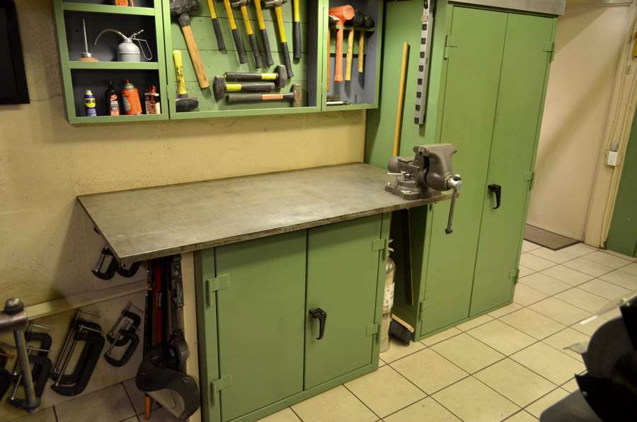
Here's the ripple effect from this little project. I kind of like the little cart -- I suspect it will come in handy working on the car. But I need a place to keep it. So I start looking around, and the best spot is down under by steel-topped bench, where I've currently got a water pressure extinguisher and a few other things stored. I'll have to move the extinguisher and a shear I was keeping back there, but that's fine. The extinguisher should be on the other side of the garage, closer to the welding table. Here's the spot:

compliancecenteragain.jpg


Now, regular readers of my online posts will know that this spot is where I recently decided to keep my push broom. I wouldn't say I'm thrilled with the solution, since the handle pops up. So I'm going to find a new spot.

But the garage is not big. And at first, the only thing I can come up with is the idea of a hook holding the broom underneath the front bench, like this:

broomidearejected.jpg


Kind of goofy, but viable. I can screw an L-shaped bolt into the underside of the table, and slide the broom out to the right when I need it.

But it bugs me, because sooner or later that's going to mean the broom hitting the parked car.

So I look at the insides of all the cabinets. No room. Except... maybe...

Here's the idea:

broomideatwo.jpg


This is the little wood cabinet where I keep a regular broom and a stepladder. I can't put the push broom on the inside of the door because the door itself is hinged into two sections, and the push broom is too wide. I'd have to shorten it again, which would be stupid.

But...

What if I could store part of the broom inside the cabinet and part of it outside, up top? All I'd need is a notch up there for the handle.

newstorage.jpg


Really? Sure. Absolutely. The only trade-off is needing to move the broom when I take out the ladder. I can live with that.

Here's what it looks like when the cabinet is closed.

broomheadt.jpg


A goofy solution, maybe. But it works.

Now to store that cart. Well, since I never planned this to work this way, the first trick is that there isn't enough room for the cart to fit.

toonarrow.jpg


All I've got to do is to slide the steel-topped bench over 3/4". That's easy, right?

Actually, it is. I run a 2x4 from the Lyon cabinet to the wall, so it won't slide to the right. Then I put a little hydaulic jack between the Lyon and the Strong Hold cabinet that's the base for the bench. A few cranks, and the 1000-pound bench moves right over.

movingthebench.jpg


One more problem. My bottle opener is too high.

bottleopenerproblem.jpg


The fix is to drill a new lower hole and move it down. Fortunately, the welder is still sitting out from working on the cart, so I'm able to fill the upper hole.

holefill.jpg


Done. Now here's where the cart stores:

cartstowed.jpg


I'm happy with that. I even get to touch up the dirty paint on the vertical cabinet while I'm at it. You can see it's still drying in the picture.

And while I'm here, I decide to find a place for a cordless LED light I got for $20 at Sears. I've used it a couple of times now, and I like it.

But it's not exactly old-school Sears construction. Part of its design is an inserted piece of paper on the back side with a bunch of useless information on it. I can't take the paper out, so I decide to cover it with a quick layer of primer and paint.

searslight.jpg


Here's the new version of the back side:

paintedtroublelight.jpg


And here's where I find room to put it. I'm able to thread its charging cord down behind the pegboard. The light itself has a magnet that will hold it to the side of my tool cabinet.

powerline.jpg


Here it is, stowed and charging. Out of sight, but still handy.

lightstowed.jpg


I've got to take it out when I want to slide one of my sledge hammers out of that space. But again, a lot of stuff is stored at double depth in my little shop. For the number of times I need a sledge hammer, this is fine.
 
Last edited:
OP
J

Jack Olsen

Super Moderator
Staff member
Joined
Mar 22, 2009
Messages
6,678
Location
Los Angeles
I found a Car in a Picture and wonder if you knew this guy... *g*

I guess you do ....
http://www.reelhouse.org/mos/urbanoutlaw/urbanoutlaw/images

Greetings
TOM
Yep, I'm lucky to know both Wayne and Magnus.

jack, i;m a caring kind of guy.
did the car take any damage?

Thanks. No damage at all. I've always been lucky on the track. (Knock on wood.)

ON THE WING

Sorry about the delay in replying to this. Here's the odd thing about the wing supports. I have a set that have been working fine for over six years. So in one sense this is an engineering problem, and in one sense it's really just a deal where I should put the old uprights back on and get on with it.

Here's a picture that shows the two new ones (and their wood model) next to one of the old ones. The two 'foot' pieces you see on the bottom of the old one were moved over to the newer pieces -- so there's no difference there.

cutuprights.jpg


The new and old ones mounted in the same way, and actually held the wing in exactly the same position, relative to the car. Both are 10-gauge aluminum (although the alloys could be different). The only change was to give the new ones a curve. But I think the biggest weakness comes from the way that curved rear support is longer and narrower -- it has to bridge a longer span and I think that made for something that was weaker, structurally.

One other thing: I think the diagonal piece that I used (which is threaded steel stock, with an aerodynamic cover which is made from a squeezed-to-shape thin steel curtain rod) was longer on the old uprights. So there was more space above where it mounts, which could have promoted some wobble.

When I do a new design, I'll post the shape here to get some input. I don't think it's an especially tough problem to solve (since my old uprights worked year after year), but I clearly made a mistake with the most-recent set.
 

Omphaloskeptic

Well-known member
Joined
Oct 11, 2008
Messages
2,346
Location
Ultima Ratio, Wa.
Don't feel too bad Jack, Wilbur and Orville didn't fly on the first try. Speaking of the Wright brothers, my suggestion early on in your (re)development of the wing using crossed guy wires came from their use on the early biplanes. It seemed to work okay for them.
 
To avoid these ads, REGISTER NOW!

Turbo1Ton

Well-known member
Joined
Dec 23, 2007
Messages
53
Re: Poor Man's Hazet Assistent (call it an Ikea-zet Assistånt?)

So I look at the insides of all the cabinets. No room. Except... maybe...

Here's the idea:

broomideatwo.jpg


This is the little wood cabinet where I keep a regular broom and a stepladder. I can't put the push broom on the inside of the door because the door itself is hinged into two sections, and the push broom is too wide. I'd have to shorten it again, which would be stupid.

But...

What if I could store part of the broom inside the cabinet and part of it outside, up top? All I'd need is a notch up there for the handle.

newstorage.jpg


Really? Sure. Absolutely. The only trade-off is needing to move the broom when I take out the ladder. I can live with that.

Here's what it looks like when the cabinet is closed.

broomheadt.jpg


A goofy solution, maybe. But it works.


That is literally thinking outside of the box! I wish my brain worked like yours. I probably have way more storage space than I can imagine but I just can't see it.

Good solution. I like the cart too. Much cheaper than the crash carts that you see at Sears and even HF. Probably better quality than the HF ones too.

Thanks for the ideas!

Jeff
 

luvit

Well-known member
Joined
Jul 11, 2011
Messages
1,580
.
heh.. looks like hindsight-steps i would do take within 5 weeks :beer:
great job both ways :beer:

attachment.php
 

Attachments

  • CropperCapture[25].jpg
    CropperCapture[25].jpg
    57.2 KB · Views: 2,222
OP
J

Jack Olsen

Super Moderator
Staff member
Joined
Mar 22, 2009
Messages
6,678
Location
Los Angeles
Yep. It definitely would fit, now. I suppose I could just buy another $12 broom head now. But the labor I've got in this one is higher than that. :)
 

Zeke

Well-known member
Joined
Aug 13, 2009
Messages
17,176
Location
Long Beach CA, the sewer by the sea.
When I do a new design, I'll post the shape here to get some input. I don't think it's an especially tough problem to solve (since my old uprights worked year after year), but I clearly made a mistake with the most-recent set.
Or you're turning faster laps in denser air. ;)

I'll see if I can locate some proper edging for CF honeycomb sheets.

Well, Googling "honeycomb edging" does produce a plethora of results. One of the best reads was here.
 

DocRocket

Well-known member
Joined
Feb 24, 2011
Messages
278
I could be seeing things in your picture, but it looks like your "old" wing support also has some kind of bent lip to the edge? That would contribute significant bending stability. Also, I would have to ask one of my structrual specialist friends, but I suspect that the curve, representing a longer path length, would decrease bending strength in your supports. In summary, I would guess: a) check the alloy (and temper), that would make a potentially huge difference, b) anything that adds "depth" to the cross section i.e. lips, "I" beam section, additional thickness, etc, will add bending stiffness far faster than adding to the long axis of the beam (double thick = 8x strong, triple thick = 27x strong, goes with depth cubed), c) reduction in that long axis will linearly affect the strength: 90% of the width == 90% of the stiffness.
 
OP
J

Jack Olsen

Super Moderator
Staff member
Joined
Mar 22, 2009
Messages
6,678
Location
Los Angeles
cutuprights.jpg


There's no bent lip. The upright was 'painted' using my own very high-tech process of covering it with adhesive-backed contact paper and then wrapping a piece of electrical tape around the edges. The surprising thing was that both of those things stayed stuck for over six years of all-weather use.

One thing I've considered has been sandwiching one or two pieces of the same aluminum to that rear section, since it's the longest curve and is probably doing most of the work. I could use a grinder then to make the overall shape more aerodynamic -- although that would be a fair amount of grinding work.

I've got two books on aerodynamics for race cars, and this graphic is the reason I'm cautious about adding a second diagonal or making the uprights thicker without rounding them off. It's why I wrapped my diagonal in a (somewhat) aerodynamic shell.

Katz1154386048.jpg
 

akdiesel

Well-known member
Joined
Aug 8, 2008
Messages
2,617
Location
Wasilla, AK
Jack

Looks like you have been busy. Being a one person operation really brings out creative ideas. I like your brace and jack to move the cabinet over.
I have the corded Craftsman LED light. I really like the light but have not put to much thought into the craftsmanship of it. Nice touch.
 

DocRocket

Well-known member
Joined
Feb 24, 2011
Messages
278
I like your painting methods. That would explain what I thought I saw.

If you are going to reinforce one end or the other, the front is probably most important. The aerodynamic forces act at the 25% chord point (from the leading edge), so the majority of the force should be carried at the front support. If machining aluminum with wood tools works for you, a double or triple thick leading edge might be rounded over with a router to streamline it a little. I suspect that not doing the cutouts would help the drag from the supports more (no 2nd leading edge), but the weight would go up, and it would not look as cool.

Love the Porsche, and the shop is, as always, great, it never fails to make me a little jealous.
 
OP
J

Jack Olsen

Super Moderator
Staff member
Joined
Mar 22, 2009
Messages
6,678
Location
Los Angeles
Thanks.

To my untrained eye, it seems like the front 'leg' of the thing would actually be in tension, not compression -- what with the drag of the wing and the cantilevered angle it sits at:

Nov+16+OTR+Jack1321641968.jpg


The airflow is also coming down on it at about 11°:

Little+Tuft+Test1331677628.jpg


Here are the old uprights in use:

Sep+21+OTR+Red+1140am+CLI_64541316672081.jpg


shakingit.jpg


I think the newer ones exaggerate the problem for the rear 'leg.'

rearuprights.jpg


readytogoo.jpg


It seems like the rear leg would collapse if I placed too much static weight on the wing, not the front. (Although, again, I'm pretty ignorant on this stuff.)

Here's the upright/diagonal combination that did the six year stunt without blinking.

Flat21316132626.jpg
 

Outlawmws

Well-known member
Joined
Aug 9, 2011
Messages
39,109
Location
The Badlands
Jack, you have to remember the wing is providing downward force not necessarily the twisting force you are intuitively thinking.

11 deg is not a really radical wing angle. We used MUCH steeper wing angles on the super-modifieds when I was racing, and we would sometimes see compression damage even on the front wing mounts.
 

Outlawmws

Well-known member
Joined
Aug 9, 2011
Messages
39,109
Location
The Badlands
Something to consider on the leading edges of the new supports: take a soft easily bent aluminum, and have someone fold a 1 or 1-1/2" strip in half with just enough gap to slip onto the leading edges of the front support and the leading edges of the middle and back supports. (you may need to make them a bit straighter), then slip this on and form them to the remaining curve. This provides both stiffness and a more aerodynamic leading edge. Attach with JB Weld. I don't think it would go anywhere.

Another option is to cut two 1/2" strips the same thickness of each vertical strut to he same curve, then drill and use both JB weld and a few aircraft rivets (Flush) to bond them on each side of the leading edge. Then get your small round over router bit and round both leading corners. You can also belt sand the trailing edges of the two strips prior to mounting to minimize the turbulence (drag) the "square" edge leaves.
 

Zeke

Well-known member
Joined
Aug 13, 2009
Messages
17,176
Location
Long Beach CA, the sewer by the sea.
11 deg is not a really radical wing angle. We used MUCH steeper wing angles on the super-modifieds when I was racing, and we would sometimes see compression damage even on the front wing mounts.

I think Jack means that the air flow over the roof is coming at the wing 11 degrees downward. I don't see the wing tilted at 11 * but that is effectively what the wing pressure is.

OK, maybe I see what you're saying. A front wing at 11* in virgin air is doing what a level wing is doing when the air is conforming to the body.
 

DocRocket

Well-known member
Joined
Feb 24, 2011
Messages
278
Just from a fluid dynamic point of view, the lift force acts about where the wing is bolted to the support (a little further back by eye). Because you have a cambered (asymetric) airfoil, there is a moment (twist) that is, in your case, pulling the leading edge up. It is very important to remember that the force does not act evenly over the surface, it is more at the center and is a suction force pulling the wing down, more than a lifting force pushing down. Also, the flow over the back of the car is almost certainly turbulent, and not following the rear deck that closely, but a reasonable place to start.

THe compression of the struts is part of the problem, looking at the video, the problem comes from a side force. If you have never tried it, a 200+lb man can stand, carefully on an empty coke can and it will support the weight until there is a side force or disturbance applied, at which point the can fails completely. That is, I think, what is going on with your struts. The force is near that limit and the side force of ~1G lateral, acting on the wing produced a force of about, what , 15 lbs (~ weight of the wing), acting at the top of the strut, horizontally. The combination of the compression and sideforce caused the strut to fail (buckle), either force on their own would not have been a problem.

A little extra thickness, from whatever method, and tempered (heat treated) aluminum might help this out. Annealed aluminum is much easier to work, but the stiffness (look at yield strength: for example, 6061 annealed yields at ~50MPa, 6061 T6 yields at 255 MPa, a 5x increase from the heat treating process). I don't know exactly what you used, and the results vary by alloy, but in all metals, the heat treatment vastly increases the yield strength.
 

58Yeoman

Well-known member
Joined
Oct 1, 2010
Messages
8,999
Location
Central IL
WOW...talk about moving a thread to the end of the line. Jack started a thread about an IKEA shelf, and it finds its' way to the back of the line. Anyway, I've got one of those Hazet Assisstents in my shop...had to dig it out to take a pic. You did a great job, Jack. I've never been to an IKEA, but I heard they are a good place to go.
 

Attachments

  • DSC00032.jpg
    DSC00032.jpg
    102.9 KB · Views: 185
  • DSC00033.jpg
    DSC00033.jpg
    104.9 KB · Views: 198

jimmie jam

Well-known member
Joined
Oct 16, 2005
Messages
490
Location
fort lauderdale, fl
Guys are spraying everything with it these days.

I got carried away with it.....wanted to paint my wheels but wasn't sure how they'd look. You can get pretty creative with this stuff. I did the wheels in "Cammo" brown, dusted them with "Gold Metalizer" and then topped with "Glossifier". Did them in July and they are still perfect :rocker:. You can even "repair" this stuff if you scrap or damage it without removing and redoing the whole item.
 

Attachments

  • CIMG1759.jpg
    CIMG1759.jpg
    47.3 KB · Views: 91
  • CIMG1760.JPG
    CIMG1760.JPG
    138.1 KB · Views: 84

Squankum

Well-known member
Joined
Mar 28, 2011
Messages
7,657
Location
Southeast
Jack:

Hazet Assistent caught my eye, too, since I love German stuff. But ya know what? Who cares if it collapses? I think the guys in that pic with the ancient aircooled VW's? That was their one and only tool box! Collapsing it was their way of locking up at the end of the day.

The main feature such a thing has is waist-high, flat surface on wheels to plop your tools and parts on near where you're working. Now, I spent many years working in parking lots, and I had to use the lid to a printer copier box on top of an old wooden chair, but now that I'm indoors and all civilized, about a year ago I purchased a Craftsman roller cart, and wow, HOW do people live without this?! And don't I want a third shelf? (I quickly got over the yearning for a middle shelf.)

Given the size of your shop, your Ikea beats a standard sized roller cart.

I also thought, what do you care about a waist-high roller cart? Your car's motor is so low you're either rolling around on your back or sitting cross-legged or kneeling on the floor and and peering in the hatch. But then I remembered, oh yeah, he has a lift now. :thumbup:

You will find yourself wondering how you lived without it in about two weeks.
 

Zeke

Well-known member
Joined
Aug 13, 2009
Messages
17,176
Location
Long Beach CA, the sewer by the sea.
Just from a fluid dynamic point of view, the lift force acts about where the wing is bolted to the support (a little further back by eye). Because you have a cambered (asymetric) airfoil, there is a moment (twist) that is, in your case, pulling the leading edge up. It is very important to remember that the force does not act evenly over the surface, it is more at the center and is a suction force pulling the wing down, more than a lifting force pushing down. Also, the flow over the back of the car is almost certainly turbulent, and not following the rear deck that closely, but a reasonable place to start.

THe compression of the struts is part of the problem, looking at the video, the problem comes from a side force. If you have never tried it, a 200+lb man can stand, carefully on an empty coke can and it will support the weight until there is a side force or disturbance applied, at which point the can fails completely. That is, I think, what is going on with your struts. The force is near that limit and the side force of ~1G lateral, acting on the wing produced a force of about, what , 15 lbs (~ weight of the wing), acting at the top of the strut, horizontally. The combination of the compression and sideforce caused the strut to fail (buckle), either force on their own would not have been a problem.

A little extra thickness, from whatever method, and tempered (heat treated) aluminum might help this out. Annealed aluminum is much easier to work, but the stiffness (look at yield strength: for example, 6061 annealed yields at ~50MPa, 6061 T6 yields at 255 MPa, a 5x increase from the heat treating process). I don't know exactly what you used, and the results vary by alloy, but in all metals, the heat treatment vastly increases the yield strength.
And there you have it, folks. One thing, too, is that Jack's cameras are always well mounted and don't shake. That doesn't mean there isn't some violence. I have been in that car as a passenger and I can tell you between the modified suspension and the condition of the track surface, there is a lot of shaking going on.

Combine the loads Doc describes with the stress of being shaken back and forth and you will find a breaking point if it's in range. I think in the video, Jack had passed the point on the track where he hits the maximum speed. Not by very far, but he does drive into and through T8 at somewhere around 130 MPH. After a short bit of straight line braking, he enters T9 at about 90.

I'll look again, but I think the uprights collapsed at the beginning of that braking point. Not breaking point. ;) :D
 
Last edited:

BEsser

New member
Joined
May 17, 2012
Messages
3
Jack,

Sorry in advance if this post lands in the wrong spot, but, who made your current tool chests, and are you happy with them? It looks like I'm heading for round three on tool boxes.
 
To avoid these ads, REGISTER NOW!
Top Bottom