To avoid these ads, REGISTER NOW!

Improvements to the MaxJax lift

Jvvmusme

Well-known member
Joined
Sep 25, 2011
Messages
566
Location
Bogota, Colombia
I have made 3 improvements to the Maxjax.

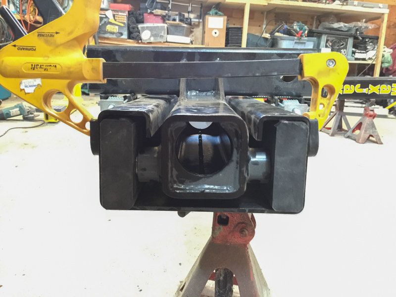
1. The maxjax comes with 2 positions for the safety steel bars. (Purple arrows). I made 2 extra set of holes in order to have aditional height positions for the safety bars (orange arrows). I never work on the MaxJax without the safety bars in place so I find that 2 extra heights is very useful.

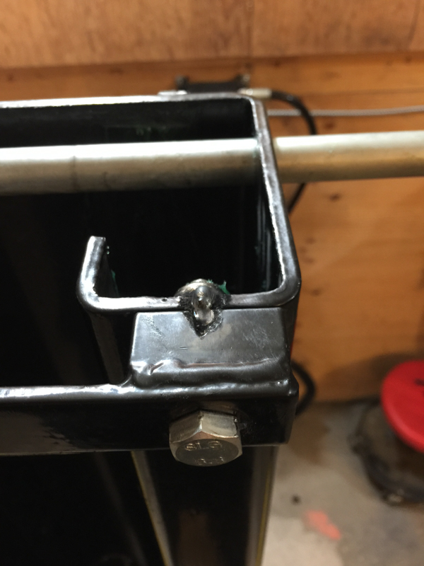
2. I installed a 1 meter long hose (green arrow) in order to place the fast release coupling at a comfortable height so I do not have to bend to connect it.

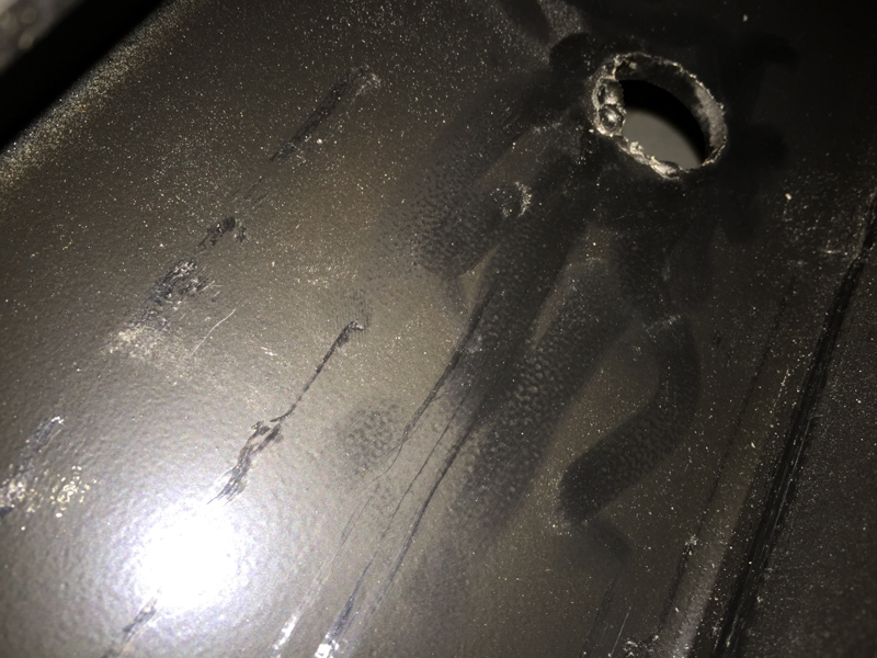
3. On the power unit I installed a 1 liter (1000 c.c.) extra tank for the hydraulic oil. I noticed that when you were lifting a car to the maximum height the MaxJax would run empty on oil for about 1 second. Even though that Danmar says this is safe and this way you know that the MAxJax is reaching maximum height I do not believe that running the pump with no oil is healthy. On the other hand this way no air gets into the hydraulic system and I do not have to bleed the system that often.
 

Attachments

  • Columna MaxJax.jpg
    Columna MaxJax.jpg
    64.8 KB · Views: 995
  • Unidad MaxJax.jpg
    Unidad MaxJax.jpg
    90 KB · Views: 761
Last edited:
To avoid these ads, REGISTER NOW!

Tarheelgarage

Well-known member
Joined
Dec 14, 2008
Messages
3,865
Location
NC
Maxjax is happy that you have modified their lift and therefore released them from any liability for any and all failures associated with your lift.....:rocker:
 

abstamaria

Well-known member
Joined
Jun 24, 2010
Messages
1,338
Location
Manila
Those are indeed improvements. I particularly like the extra extra safety stop holes and the extra oil reserve. Many thanks!

Andy
 

rbonitz

Well-known member
Joined
Oct 25, 2012
Messages
140
Yeah - the lack of holes for safety stops is borderline ridiculous....
 

NewShockerGuy

Well-known member
Joined
Oct 12, 2010
Messages
2,481
Location
Northern Virginia / DC
Glad I found this thread. Not to sound like an idiot but did you drill the new holes with a hand drill? And if so what size bit and any helpful hints on doing it? IE: Do you have to remove the cylinder to make sure metal scraps don't get into areas where they should not...

Seems like a good deal. I especially like the lower hole which would be useful for changing tires that you don't really need to lift the car up real high...etc.

I also like the little fluid that you added. What parts did you use to make such a thing?

Thanks,
-Nigel
 
OP
J

Jvvmusme

Well-known member
Joined
Sep 25, 2011
Messages
566
Location
Bogota, Colombia
Glad I found this thread. Not to sound like an idiot but did you drill the new holes with a hand drill? And if so what size bit and any helpful hints on doing it? IE: Do you have to remove the cylinder to make sure metal scraps don't get into areas where they should not...

Seems like a good deal. I especially like the lower hole which would be useful for changing tires that you don't really need to lift the car up real high...etc.

I also like the little fluid that you added. What parts did you use to make such a thing?

Thanks,
-Nigel

1. 1/2 hand drill. Started with 5mm drill and up until reaching the correct hole. 3 steps. I do not remember the final size.... But the same as original

2. I removed the cylinders. Yes

3. Lower hole perfect for tyre changes

4. A 1 liter bottle, 2 couplings, a hose and lots of silicone and sykaflex
 

rickyboy

Well-known member
Joined
Oct 21, 2012
Messages
90
Location
Langley, BC Canada
All great ideas and suggestions. Thanks!!

I'll be subscribing to this thread so I can refer to it when I get started outfitting my garage. {retirement is just around the corner I hope}
 

NewShockerGuy

Well-known member
Joined
Oct 12, 2010
Messages
2,481
Location
Northern Virginia / DC
Can you give us the measurements that you used for the new drill holes. I'd like to do this before actually setting everything up now, then I can paint the holes and make it look OEM.

Thanks again for the info!

-Nigel
 

In My Garage

Well-known member
Joined
Jul 28, 2011
Messages
315
Location
ON
MaxJax ought to have the supplier of the hydraulic flow divider install a shorter fastener in the location yellow circled.

That fastener sticking out makes it impossible to get an open-end wrench on the hose fitting for tightening.

Before:
IMG_3144a-L.jpg


After:
IMG_3145-L.jpg
 

koditten

Well-known member
Joined
Apr 10, 2008
Messages
5,528
Location
Midland, Michigan
I'm glad I'm not the only one that is gonna mod their lift. Mine (in the process of erecting it as we speak) is a 2 post. There is going to be all sorts of brackets attechad to mine when I'm done.

KO
 

Nostraquedeo

Well-known member
Joined
Oct 23, 2009
Messages
501
Maxjax is happy that you have modified their lift and therefore released them from any liability for any and all failures associated with your lift.....:rocker:

I see he is in Colombia.....maybe not so many sue happy people there as in the US. Don't know that for sure, but I have to imagine we are the most sue happy country in the world!
 

In My Garage

Well-known member
Joined
Jul 28, 2011
Messages
315
Location
ON
Re: Improvements to the MaxJax Instruction Manual

Improvements to the manual...

Nowhere (unless someone can point me to the page and diagram number) does the MaxJax manual show you how to orient the UHMW load bearing blocks that pivot on the pins of the MaxJax lift head. Since the hydraulic cylinders are removed to install the fittings and since the UHMW load bearing blocks can spin, it might be a good idea if they revised the MaxJax manual.

The UHMW load bearing blocks are not symmetrical...
MaxJax%20UHMW%20Load%20Bearing%20Block-L.jpg


Sources:
MaxJax Instruction Manual - Revision Rev B 7-2011.
MaxJax Instruction Manual - Revision Rev C 2-2012.
 
To avoid these ads, REGISTER NOW!
OP
J

Jvvmusme

Well-known member
Joined
Sep 25, 2011
Messages
566
Location
Bogota, Colombia
Re: Improvements to the MaxJax Instruction Manual

Improvements to the manual...

Nowhere (unless someone can point me to the page and diagram number) does the MaxJax manual show you how to orient the UHMW load bearing blocks that pivot on the pins of the MaxJax lift head. Since the hydraulic cylinders are removed to install the fittings and since the UHMW load bearing blocks can spin, it might be a good idea if they revised the MaxJax manual.

The UHMW load bearing blocks are not symmetrical...
MaxJax%20UHMW%20Load%20Bearing%20Block-L.jpg


Sources:
MaxJax Instruction Manual - Revision Rev B 7-2011.
MaxJax Instruction Manual - Revision Rev C 2-2012.


I agree with the fellw member who owns a beatifull yellow Porsche 993.....

If you not install these blocks correctly or at least all aligned in the same direction the maxjax with lower with difficulties when unloaded
 

NewShockerGuy

Well-known member
Joined
Oct 12, 2010
Messages
2,481
Location
Northern Virginia / DC
Thanks for the info!! I did the same thing to my maxjax as well, added two holes! Came out perfect!

Although the stock holes were 21mm big, mine are 23mm but don't think that really matters much because they are level and even on each side. I just couldn't find a 21mm bit anywhere, so I used my unibit that was 23mm.

20130331_144401.jpg


20130331_145318.jpg


-Nigel
 
Last edited:

sidwin

Well-known member
Joined
Mar 30, 2014
Messages
49
i took two 12 inch paint rollers and slit them down the middle. then i slid them over the silver pins. that way when i open my door on my 997 it doesn't hit and scratch the car. :)

i also added 4 feet of hoses to the left arm so i could route the hoses nice and clean.
 

sidwin

Well-known member
Joined
Mar 30, 2014
Messages
49
got my 1 ft lines. if anyone wants to get it done, i went with 3500 psi aeroquip. then one side is 3/8npt and the other side is 1/2npt. that way i now have no fittings until i hit the quick connect. makes the install so much cleaner. you can also take this time to get the 90 degree elbow put in so your line can lay flat. not a single drop. definitely makes me feel better than having all those fittings. maxjax should have done it backwards. the fittings should have been on the pump side and all the hoses say with the post. that way if there was a leak it would be so much easier to troubleshoot. it would have been nice if they used AN fittings instead of NPT. Those hoses would line up so much easier as well.

Thanks,
Sid

here are pics of both the line i added. the paint rollers. i also bought table edge guard from amazon to protects my bigger cars from opening and hitting the post.
http://www.amazon.com/gp/product/B005ZNCS3Y/?tag=atomicindus08-20
 

Attachments

  • IMG_2237[1].jpg
    IMG_2237[1].jpg
    130 KB · Views: 319
  • IMG_2236[1].jpg
    IMG_2236[1].jpg
    141.9 KB · Views: 328
  • IMG_2235[1].jpg
    IMG_2235[1].jpg
    141.9 KB · Views: 376
Last edited:

jdm5

Well-known member
Joined
Jan 1, 2012
Messages
281
Location
CT
Wired Remote control! (up only so far)

Got my MaxJax installed over the last couple weeks. Loved it; but having tried the Bendpak QuickJack BL-5000 I really wanted a wired remote on the MaxJax...so I installed one.

Wired%20Remote_zpsxqnvtm65.jpg


This is a pretty straightforward modification and I'm finding it really helpful. Note that it only works for going UP right now - down is obviously not electrical on the MaxJax; I'm interested if anyone has an idea to find a solenoid or actuator to bring it down electrically - it would be relatively easy to add that.

  1. Purchase the wired remote. I went with this one - definitely not cheap (~$100), but it's a quality unit. I have no affiliation with the vendor - if someone finds one cheaper please let me know.
  2. Purchase a wire connector for the remote cable to connect to the electrical box on the pump unit. I went with the Arlington 4JWN2. It worked great; definitely tight, easily fits in the box. (any knockout connector for this type of cable would be fine)
  3. Knockout the electrical knockout. I've worked with a fair number of knockouts in electrical boxes - but the pump unit's electrical box is not a standard 'knock it out with hammer and slotted screwdriver' deal. After bending my box a bit, I resorted to my Greenlee knockout punch set - you definitely need this (or something like it) to get these knockouts out. I used the top right one - gave me plenty of room.
  4. Wire it up! I popped open the remote to check the wiring; on the one I received white was the up conductor, black was common, and green is down:
    Inside20Wiring20of20remote_zpsjtuy246h.jpg


    Open the electrical box on the pump unit. It uses this contact switch; there are two blue wires running to it:
    Contact%20Switch%20for%20MaxJax_zpswoha9uqd.jpeg
    .

    I wired the remote in parallel with the existing switch - running my switch's white to one of the blues, my black to the other blue. Then continue the joined wires to the original terminals on the contact switch using 6" of 14 ga wire to pigtail the connections - it doesn't matter which is which.

This works GREAT - I can now walk around while raising my car to confirm everything is clear.

If anyone has suggestions for electrically LOWERING it please share!
 

In My Garage

Well-known member
Joined
Jul 28, 2011
Messages
315
Location
ON
Re: Wired Remote control! (up only so far)

If anyone has suggestions for electrically LOWERING it please share!

As you already mentioned, a solenoid come to my mind as well.

It doesn't take much at the end of that lever. I use a rubber band to hold the lever in when lowering.

You do want a manual quick-disconnect something like a pull pin.
 

Denwood

Well-known member
Joined
Sep 22, 2014
Messages
4,183
Location
Thunder Bay, Ontario, Canada
Just a minor tweak during install. When fully raised there was quite a bit of slop in the lift carriage. I clamped the end of each post so there was near zero clearance (at full lift), bolted on the top tie bar, and tacked it in place with the MIG. Makes for a much more solid (no rocking back and forth) lift.

Picture 1 showed the internal burr left by the factory. This would eventually machine out a chunk of the UHD plastic, particularly given my squeeze "mod", so I cleaned these up.

When fully raised, the slide blocks at the top have less then 1/32" of an inch play after the tweak, vs nearly 1/4" had I left it alone. That 1/4" translated out 7' to the bumper is a lot of movement possible if the car is balanced on the lift and you're wailing on a part.

max1.jpg


max2.jpg


max3.jpg
 
Last edited:

Cobra96

Well-known member
Joined
Jul 29, 2014
Messages
88
Re: Wired Remote control! (up only so far)

Got my MaxJax installed over the last couple weeks. Loved it; but having tried the Bendpak QuickJack BL-5000 I really wanted a wired remote on the MaxJax...so I installed one.

Wired%20Remote_zpsxqnvtm65.jpg


This is a pretty straightforward modification and I'm finding it really helpful. Note that it only works for going UP right now - down is obviously not electrical on the MaxJax; I'm interested if anyone has an idea to find a solenoid or actuator to bring it down electrically - it would be relatively easy to add that.

  1. Purchase the wired remote. I went with this one - definitely not cheap (~$100), but it's a quality unit. I have no affiliation with the vendor - if someone finds one cheaper please let me know.
  2. Purchase a wire connector for the remote cable to connect to the electrical box on the pump unit. I went with the Arlington 4JWN2. It worked great; definitely tight, easily fits in the box. (any knockout connector for this type of cable would be fine)
  3. Knockout the electrical knockout. I've worked with a fair number of knockouts in electrical boxes - but the pump unit's electrical box is not a standard 'knock it out with hammer and slotted screwdriver' deal. After bending my box a bit, I resorted to my Greenlee knockout punch set - you definitely need this (or something like it) to get these knockouts out. I used the top right one - gave me plenty of room.
  4. Wire it up! I popped open the remote to check the wiring; on the one I received white was the up conductor, black was common, and green is down:
    Inside20Wiring20of20remote_zpsjtuy246h.jpg


    Open the electrical box on the pump unit. It uses this contact switch; there are two blue wires running to it:
    Contact%20Switch%20for%20MaxJax_zpswoha9uqd.jpeg
    .

    I wired the remote in parallel with the existing switch - running my switch's white to one of the blues, my black to the other blue. Then continue the joined wires to the original terminals on the contact switch using 6" of 14 ga wire to pigtail the connections - it doesn't matter which is which.

This works GREAT - I can now walk around while raising my car to confirm everything is clear.

If anyone has suggestions for electrically LOWERING it please share!

Great idea especially for using motorcycle adaptor. My pump is on the wall away from the posts.
What kind of remote and where did you get it. One thing that I didn't understand about your connection was the pigtail. The two wires that come from the remote cable should just connect in parallel with the two blues. I haven't opened my box yet so I'm not sure about the connection . Do you have to cut the two blues to create the pigtail ?
Thanks
Chuck
 

jdm5

Well-known member
Joined
Jan 1, 2012
Messages
281
Location
CT
Hey Chuck,

I got it here - not affiliated with them at all.

Sorry if the pigtail reference was confusing, specifically on the wiring I:

  1. Removed the blue wires from the existing contact switch (they are simple flat blade screw terminals)
  2. Cut the ends off the blue wires (they had soldered on a flat terminal designed for the existing contact switch). I then stripped the ends of the now cut wire
  3. Wired one of each of my switch's wires to the existing blue wires. So my white to one of the blue wires, my black to one of the blue wires.
  4. Added what I referred to as the pigtail, a small length of 14 ga wire from the blue wire + each of my wires to each side of the blue contactors from step #1 above. So first set of wires = blue wire #1 (arbitrary) + my white wire from the switch I bought + white 14 ga wirenutted together, and the 14 ga white runs to one side of the existing blue contact switch. Then second set of wires = blue wire #2 (the other one) + my black wire from the switch I bought + black 14 ga wirenutted together, and the 14 ga black runs to the other side of the existing blue contact switch.

Honestly it sounds more complicated than it is - it's really straightforward once you get in there, and there's plenty of room to work - I do recommend using the top right knockout though (when looking straight on at the pump unit / electrical box). And like I said earlier DEFINITELY use a knockout punch set - I was not able to just hammer off the knockout like I normally have.
 
Last edited:

laser3kw

Well-known member
Joined
Nov 17, 2012
Messages
7,276
Location
northen IL
I have been lurking around the Max Jax idea for a while. I like what you guys have done.
Are there any of you Max Jax owners around the Rockford IL area that would welcome a visitor? I would like to see one in action.
Thanks
 

Cobra96

Well-known member
Joined
Jul 29, 2014
Messages
88
Hey Chuck,

I got it here - not affiliated with them at all.

Sorry if the pigtail reference was confusing, specifically on the wiring I:

  1. Removed the blue wires from the existing contact switch (they are simple flat blade screw terminals)
  2. Cut the ends off the blue wires (they had soldered on a flat terminal designed for the existing contact switch). I then stripped the ends of the now cut wire

  3. Wired one of each of my switch's wires to the existing blue wires. So my white to one of the blue wires, my black to one of the blue wires.
  4. Added what I referred to as the pigtail, a small length of 14 ga wire from the blue wire + each of my wires to each side of the blue contactors from step #1 above. So first set of wires = blue wire #1 (arbitrary) + my white wire from the switch I bought + white 14 ga wirenutted together, and the 14 ga white runs to one side of the existing blue contact switch. Then second set of wires = blue wire #2 (the other one) + my black wire from the switch I bought + black 14 ga wirenutted together, and the 14 ga black runs to the other side of the existing blue contact switch.

Honestly it sounds more complicated than it is - it's really straightforward once you get in there, and there's plenty of room to work - I do recommend using the top right knockout though (when looking straight on at the pump unit / electrical box). And like I said earlier DEFINITELY use a knockout punch set - I was not able to just hammer off the knockout like I normally have.


Excellent, I want to do this eventually to use the bike adaptor.

How do you like the lift so far..., how long have you had it?

Thanks again....
Chuck
 

jdm5

Well-known member
Joined
Jan 1, 2012
Messages
281
Location
CT
I just installed it a few weeks ago - haven't even had a chance to get a car up on it (waited for the epoxy to set, then had to work, then saw the recall notice popped up yesterday so didn't try to put a car on it this weekend until that gets sorted out).

Conceptually it should be great for me - I spent today mounting the pump unit on the wall and measuring to have custom host lines made up so I can plumb it in permanently and not have hoses around.
 

Cobra96

Well-known member
Joined
Jul 29, 2014
Messages
88
I dint receive the notice ... Yet. I bought mine the last week of July. So we'll see!
I first set it up out side but didn't have the weather to use it, then did some
to my garage so I could set it up in there, mounted the pump on the wall, upgraded with longer hoses and better fittings. I finally used it to do an alternator, water pump, heater line and ball joints on my dodge caravan. GREAT TOOL! Your gonna live it...., just get some safety stands for piece of mind!
Being I bought mine in July , I don't think I'm part of the lot that had the issue. I do believe however, hat Danmar may have more than one factory making these things based upon inconsistencies with how they come and what it comes with upon arrival like square lift pads versus round!
 

ymurf

Well-known member
Joined
Jul 7, 2015
Messages
116
Location
Steelville,Mo
Well crud, I may be missing something else with my maxjax..On page one of this thread there is a picture of UHMW load bearing blocks? What are these and where are they suppose to go?
 

ymurf

Well-known member
Joined
Jul 7, 2015
Messages
116
Location
Steelville,Mo
Well crud, I may be missing something else with my maxjax..On page one of this thread there is a picture of UHMW load bearing blocks? What are these and where are they suppose to go?

Never mind,Mine are in there.The pic of yours makes them look like small blocks.
 

PotteryPal

Member
Joined
May 31, 2015
Messages
9
Location
Montgomery, TX
This is the exact problem I am having. Too much left to right motion in the nylon block to the steel track. I was thinking about having a new set machined to tighter tolerances.

This extra play is causing my lift to bind when trying to lower it. Bad/cheap design by Danmar.
 
To avoid these ads, REGISTER NOW!
Top Bottom