To avoid these ads, REGISTER NOW!

VISE REPAIR 101 all vise repairs, lubricants, sources for parts and the tricks to fix

OP
D

drivesitfar

Well-known member
Joined
Oct 23, 2013
Messages
36,008
Location
Pacific Northwest
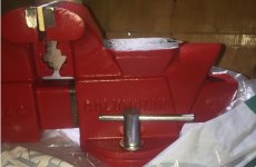
Shift: I suppose in another 100 years these vises with missing letters, upside down letters or unusual casts might make them more valuable sort of like old coins and other collectibles so if you live long enough...

nice looking vise and great find.

sorry to hear about the fires that seemed to be burning California on a regular basis earlier this year. since you are a bit closer and we haven't heard too much about them did you drive through the areas and are they rebuilding or does it look like a forest fire and everyone left?

Carla: always love your informative posts that is for certain. just want to add to your post about the #'s of the Reeds and note that Reed also made some 8 and 9 inch 250+ pound vises. speaking of them have you seen any of the big ones in your travels? Reed 108, 208, 408, 109, 209?

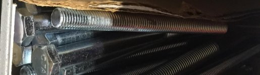
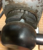
ALL: while we are talking about punching pins up from below are all Reed pins like that? i seem to recall that maybe some were threaded or would that have been something a user did and it never left Reed's factory like that?
 
To avoid these ads, REGISTER NOW!

txlonghorn1989

Well-known member
Joined
Feb 27, 2017
Messages
2,786
Tex: great to see you found a nice Reed vise in the wild cause those that left the factory prior to 1960 are some of my favorites.

...

good luck with your spiffing up and if you are liking the old paint and don't want to take it down to bare metal do like i did on my Reed 2c and just clean it up and put BLO over the old paint. I kinda like it that way too.

good luck and nice find!

<B>drives</B>,
Thanks! I guess you missed my post about finding my first Reed about a month ago. It was a Reed 104-1/2 R. Sadly, the dynamic jaw support was broken off. That bothered me a lot and I decided to resell it. I really like the look of those Reed 10x R vises! Still hoping to one day see or better yet find a Prentiss or Rock Island example. This find was totally unexpected.

Love that look on your vises where you left the original paint and then used BLO. I will definitely be trying that for the first time!
 

txlonghorn1989

Well-known member
Joined
Feb 27, 2017
Messages
2,786
Going on a day of that swivel lock soaking in PB Blaster. I've probably hit it 5 times during that period with another shot or two. What is the preferred method to put some torque on the swivel lock handle? Thus far I've only tried to move it by hand. I'm thinking a 1'-2' piece of 1/2" pipe. ???

I also don't have a drag link socket and hate to spend $15-$20 on one. May try to wedge a big screwdriver in there sideways and get some leverage on the swivel base bolt. Although I hate to mar this old vise even where it isn't normally visible.

Thanks!
 

va.grouseman

Well-known member
Joined
Mar 26, 2011
Messages
4,965
Location
Southern-Central VA.
It slips my mind, and that's no surprise, but someone on this thread made the perfect homemade drive link socket out of a disposal 1/2'' drive socket by cutting 2 notches in it and welding 1/2 of a big washer into the notches.---(You can cut the notches with a Dremel tool and a cut-off wheel). And If that person would please come forward and repost, I would much appreciate it so I can file his technique for posterity.


Tex, you may as well get one or make one, cause you're probably hooked, so this won't be the last time you hit this same wall.


Do you have a cheap broad bladed chisel which usually are hexagon shafted that you could grind to shape.---You could use a socket, a wrench, or an adjustable wrench on it.
 

chrisnazzy

Well-known member
Joined
Apr 20, 2013
Messages
1,671
Location
Arizona
My solution for slotted shoulder bolts. You could probably pick up a large chisel with a hex shank at most hardware stores and then just find a corresponding socket.20171030_185804.jpg

Sent from my SM-G930P using Tapatalk
 

va.grouseman

Well-known member
Joined
Mar 26, 2011
Messages
4,965
Location
Southern-Central VA.
Yea, that's even better Chris.---But need to go gingerly on the impact.---If the bolt is stuck good-fashion, that would be the immovable object and the irresistible force.---Something bad is about to happen.:shocking::eyecrazy:
 

Muggzy

Well-known member
Joined
Jun 29, 2013
Messages
583
Location
Orange Co., NY
Ok, so here's the before and "almost" after... The third picture is my little problem. The lock-down bolt had to be cut out because the nut on the back side was thoroughly rusted to the bolt. Actually it was the nut that was cut off. My problem is reproducing (or replacing) the bolt. I thought I would use a shoulder bolt and round the head over, but 3/8"-16 shoulder bolts only come with 1/2" dia. shoulders. I don't have a lathe. Any suggestions? IMG_20180127_143827.jpegIMG_20180603_132314.jpeg

Sent from my Pixel XL using Tapatalk
 

Shiftless

Well-known member
Joined
Mar 9, 2014
Messages
14,529
Location
East Bay SFO
Nice job on the repaint!

Would it be heretical to suggest using an ordinary bolt coming up from unerrneath and fastened with a stainless steel acorn nut and washer?

Can you unscrew the cut off bolt from the handle assembly? Why do you need a shoulder bolt anyway? Could you use a regular bolt with a steel sleeve or bushing?
 
Last edited:

Muggzy

Well-known member
Joined
Jun 29, 2013
Messages
583
Location
Orange Co., NY
Nice job on the repaint!

Would it be heretical to suggest using an ordinary bolt coming up from unerrneath and fastened with a stainless steel acorn nut and washer?

Can you unscrew the cut off bolt from the handle assembly? Why do you need a shoulder bolt anyway? Could you use a regular bolt with a steel sleeve or bushing?
Thanks Shiftless. To be honest, it was a little more than a simple repaint. Just about everything underneath the vise was rusted like it had been sitting in salt water. Took quite a lot of coaxing and cutting to get it all apart. Also had to make one of the Jaws and polish the "bullet" on the front of the screw. I'm trying to finish this to give to my son as his first father's day gift from me and though its not a real valuable vise, I'd like it to be as faithfully restored as possible.

Your idea of coming up from the bottom with a bolt is a pretty good one. If I don't come up with a better solution, that's gonna be the fix. Thanks!

Sent from my Pixel XL using Tapatalk
 
Last edited:

Outlawmws

Well-known member
Joined
Aug 9, 2011
Messages
39,189
Location
The Badlands
Muggzy, a couple of ideas:

Try looking at std replacement lawnmower axle bolt. if the threaded part is long enough you can cut off the head and chuck it in a DP and file it while spinning.

The other option might be to get a stud, thread and bottom that into a 3/8 all thread coupler, and then file the points so its 12 sided; then do the drill press/file routine from above. cross drill for the handle and that will also lock in the stud if it need it.
 

Fretters

Well-known member
Joined
Jan 25, 2014
Messages
4,217
Location
South Yorkshire, England
Cut the threaded portion off square with the shank, drill and tap the shank end with something like a 3/16” tap, drill and tap the end of a 3/8" piece of threaded rod the same, and couple both parts together with a 3/16" stud. Loctite or braze to bond them permanently.
 

Shiftless

Well-known member
Joined
Mar 9, 2014
Messages
14,529
Location
East Bay SFO
Cut the threaded portion off square with the shank, drill and tap the shank end with something like a 3/16” tap, drill and tap the end of a 3/8" piece of threaded rod the same, and couple both parts together with a 3/16" stud. Loctite or braze to bond them permanently.

Fretters has a good idea there. But I wouldn’t try it without a drill press and a good DP vise locked down to the DP table. Accuracy and personal safety are both really important.
 

gman007

Well-known member
Joined
May 17, 2017
Messages
2,726
Location
West Michigan
Any ideas where I can source this bolt or make one without a lathe? IMG_20180603_153824.jpeg

Sent from my Pixel XL using Tapatalk
Muggzy For one of the very first vises that I restored which was a cheap Columbian D44 with missing swivel arm, I figured it was not worth it to get a professional swivel arm made. Plus it was fun to make something myself. So I decided to make one myself with nothing more than a drill press , tap set, file and a hack saw (even though I had an angle grinder with cutting disc I wanted to make sure I have good control over the cut).

I used a 1/2" inch bolt and cut a 1.5" tall piece of the none thread part (to be honest probably 1.25" tall would have been better). I then drilled and taped this cylindrical piece about 0.8" deep to accept a 3/8" bolt. I also cut off 4" of a none threaded part of the a 1/4" bolt to make the arm. I drilled a horizontal hole through the 1/2" cylinder and fit the arm and then peened the end of the arm. I did used the file as needed.

While it this is not obviously a professional swivel arm, it is completely functional and it does look like a swivel arm and in my books beats a simple nut and bolt (which is most people seem to use for missing swivel arms).

Here are some photos of the swivel arm.
 

Attachments

  • D44 columbain 1.jpg
    D44 columbain 1.jpg
    59 KB · Views: 38
  • d44 swivel arm .jpg
    d44 swivel arm .jpg
    37.4 KB · Views: 34
  • Bolts D44 IMG_1150.jpg
    Bolts D44 IMG_1150.jpg
    81.1 KB · Views: 34

Muggzy

Well-known member
Joined
Jun 29, 2013
Messages
583
Location
Orange Co., NY
Some very good ideas here. Thank you all. I'll post some step by step pics to share.

Sent from my Pixel XL using Tapatalk
 

Muggzy

Well-known member
Joined
Jun 29, 2013
Messages
583
Location
Orange Co., NY
So if you're interested in a before pic check out post #6133 above.
Based on some really good ideas from you people on GJ, here's what's been done to recreate the swivel locking bolt and nut;
1 3/8-16 bolt, a 5/8 bolt for the round stock and a 4" 1/4-20 for the arm... IMG_20180604_163420.jpeg

Drilled the 5/8 bolt with a 23/64 and press fit the 3/8 threads into the 5/8 bolt head with some loctite 640 Sleeve Retainer... IMG_20180605_163343.jpeg


Then the head was lopped off. With the threads in a drill and a flap disk in the grinder the 5/8 shank was rounded over... IMG_20180605_164347.jpeg

Drilled the top for the 1/4-20 and gave the 1/4-20 head and nut the same treatment with the drill/grinder combo...IMG_20180605_165715.jpeg
IMG_20180605_183831.jpg


And then made the nut out of some 1/4" scrap mtrl that was laying around...
IMG_20180605_190254.jpeg
IMG_20180605_193117.jpeg

And the finished vise (drum roll please)...
IMG_20180605_184038.jpeg

Sent from my Pixel XL using Tapatalk
 
Last edited:
To avoid these ads, REGISTER NOW!

txlonghorn1989

Well-known member
Joined
Feb 27, 2017
Messages
2,786
the first 6 inch wide jaw I bought was a Rock Island 577. It was sitting on a rusty piece of steel I beam and was a rust bucket because it was in my client's carport after he saved it out of the family barn that had long since fallen down. he was 75 years old and his dad was the original owner of this 1935 beauty.

back to the story. I saw it and was amazed at how big it was even compared to the Wilton C1 vises I had owned. I turned the handle and there I was hooked. I unscrewed it all the way and loaded it in two parts into my Honda on a couple hunks of cardboard and drove home with a huge smile on my face.

unfortunately I found that 3 screws in the jaws were missing, 2 more were stripped and one broke inside the hole. so I asked my friend what he thought the best fix was to make it a usable vise. we both voted to JB Weld the jaws on and it worked fine that way until I met a very handy machinist recently that was able to heat the jaws off, drill new holes and rethread and put new screws in each jaw. now I have a 150 pound 80 year old 6 inch jaw vise that is in great shape. my machinist said the jaws were some of the hardest metal he had ever drilled and didn't want to do another job like that anytime soon.

here's the vise so this thread can have a few pictures.

Great story, really good looking vise Drives!
 
OP
D

drivesitfar

Well-known member
Joined
Oct 23, 2013
Messages
36,008
Location
Pacific Northwest
Muggsy: great job on that repair job fabbing up that part. VERY WELL DONE!!

also thanks for all the great pictures and descriptions. i'm not sure about the SAFETY of running your hand grinder upside down and putting your part in a drill because i probably would have used a bench or belt grinder, but You sir GOT R DONE!!

was drilling the hole in the bolt for the pin very tough and any issues with it moving or how did you secure it?

TEX: thanks for bringing up that story that I probably wrote a few years ago when I started this thread and yep I still own that Rock Island 577. I need to mount it on my 800 pound bench if I can get the bench moved from storage to my garage.

how are you liking your growing Reed collection? have you given the BLO a try yet?
 

Attachments

  • WP_20150627_001.jpg
    WP_20150627_001.jpg
    71.1 KB · Views: 26

Muggzy

Well-known member
Joined
Jun 29, 2013
Messages
583
Location
Orange Co., NY
Muggsy: great job on that repair job fabbing up that part. VERY WELL DONE!!

also thanks for all the great pictures and descriptions. i'm not sure about the SAFETY of running your hand grinder upside down and putting your part in a drill because i probably would have used a bench or belt grinder, but You sir GOT R DONE!!
Thank you kindly. You can't tell from the picture but the grinder was wrapped in a rag and secured in a vise to hold it. I worked the shaping by working the drill at low speed with the wheel spinning away from me at the point of contact.

was drilling the hole in the bolt for the pin very tough and any issues with it moving or how did you secure it?
I have a small drill press vise that has horizontal and vertical v-grooves. The only difficulty is accurately centering the holes to start. Used the centering head on my combination square for the bolt end and eyeballed the cross hole once I centerpunched it. Just had to VERY carefully set things up. Otherwise it was kinda easy, just use plenty of oil, pilot holes, and sharp drill bits. If the bolt had been some kind of high grade bolt, it probably would have been a different story.


Sent from my Pixel XL using Tapatalk
 
Last edited:

Muggzy

Well-known member
Joined
Jun 29, 2013
Messages
583
Location
Orange Co., NY
Cut the threaded portion off square with the shank, drill and tap the shank end with something like a 3/16” tap, drill and tap the end of a 3/8" piece of threaded rod the same, and couple both parts together with a 3/16" stud. Loctite or braze to bond them permanently.
Fetters, I have to thank you personally for a great idea. Also, I had it in my head that I needed to weld the pieces together, but for this application loctite is perfect! Both the bolt and the rounded over nut on the handle. [emoji482]

Sent from my Pixel XL using Tapatalk
 

trijeff

Well-known member
Joined
Jan 21, 2015
Messages
1,359
Location
Northern Cali
yeah, I'm going to do something similar for the shoulder bolt I had to partially destroy to get the base off of a Reed 1C

Sent from my SM-G900T using Tapatalk
 

Muggzy

Well-known member
Joined
Jun 29, 2013
Messages
583
Location
Orange Co., NY
yeah, I'm going to do something similar for the shoulder bolt I had to partially destroy to get the base off of a Reed 1C

Sent from my SM-G900T using Tapatalk
Glad to be able to contribute to the GJ in some small way. [emoji481]

Sent from my Pixel XL using Tapatalk
 

txlonghorn1989

Well-known member
Joined
Feb 27, 2017
Messages
2,786
TEX: thanks for bringing up that story that I probably wrote a few years ago when I started this thread and yep I still own that Rock Island 577. I need to mount it on my 800 pound bench if I can get the bench moved from storage to my garage.

how are you liking your growing Reed collection? have you given the BLO a try yet?

Drives,
Only got the Reed 214R, I released the 104-1/2 R back to the wild. It actually went to a guy with a welding shop. He was excited to get it. Like I've said the Reeds don't show themselves here in the Texas Hill Country very often. I'll keep looking though!

I'm gonna try the BLO on a piece of railroad track I've got before I do the 214R.
 

txlonghorn1989

Well-known member
Joined
Feb 27, 2017
Messages
2,786
Update on my Reed 214R restoration:

I've got it all apart and nearly cleaned up. At least all of it that I intended to take apart after getting advice here. Then today I decided I wanted to see how hard or easy it was to get the split nut backed out. It came out easily with light tapping from a ball peen hammer on a punch. I recalled reading someone's comment about it being in 2 pieces and it's called a "split" nut so I was very careful as I was approaching removal but I'm also thinking it may be in two pieces that some how merge together as it is tightened. Once it was ready to just pull it out I took a close look and I see what's in the pic. I'm thinking "so it is actually a "split" nut. But it doesn't look that clean so I lean in for a closer look and it's clear that is a break!

I didn't remove it. I immediately screwed it back in by hand. I haven't tightened it down as of yet. I wanted to see what you guys advise. So what the heck do I do now? Tighten it back up and just make sure I don't use it was an anvil? Something else? I'm assuming these split nuts don't grow on trees. Maybe I'm wrong. ???

Advice at this point please!!!

Thanks, Mike
 

Attachments

  • IMG_6902.jpg
    IMG_6902.jpg
    99.2 KB · Views: 34

Fretters

Well-known member
Joined
Jan 25, 2014
Messages
4,217
Location
South Yorkshire, England
That's how cast pieces are split. They're snapped in half after they're finished. It was a common technique at one time. A single piece, machined, finished etc., and then they crack the piece so that you can place it over a larger protrusion.

Once the two halves are mated back together, they form a perfect piece. It's also impossible to mate pieces incorrectly, as the crack makes sure that only the correct two faces, in the correct orientation, will ever mate correctly.
 
Last edited:

gman007

Well-known member
Joined
May 17, 2017
Messages
2,726
Location
West Michigan
That's how cast pieces are split. They're snapped in half after they're finisrhed. It was a common technique at one time. A single piece, machined, finished etc., and then they crack the piece so that you can place it over a larger protrusion.

Once the two halves are mated back together, they form a perfect piece. It's also impossible to mate pieces incorrectly, as the crack makes sure that only the correct two faces, in the correct orientation, will ever mate correctly.

Adding to what Fret said, at a first glance one might think of other methods such as cutting the ring at two different angles at two different places to ensure that the two halves always mate correctly but then one has to deal with the fact that cutting no matter how finely done will lead to loss of material and the two halves will have a gap between them when put back together! So as Fret implied this is in fact a rather ingenious solution!


Ps
Here is the split ring from my 404 1/2 R. Bottom line it is safe to remove it!
So
 

Attachments

  • 3E9238F7-C552-467B-85A7-DB8394D71E92.jpg
    3E9238F7-C552-467B-85A7-DB8394D71E92.jpg
    146.8 KB · Views: 34
Last edited:
OP
D

drivesitfar

Well-known member
Joined
Oct 23, 2013
Messages
36,008
Location
Pacific Northwest
Tex: you must have read all the fun warnings we've written about VISE ADDICTION so good for you for finding a good home for the other Reed you didn't need.

yep you can take the split nut out of your Reed and when you put it back together just remember to put back in the little set screw. if you have time to read that thread I posted a link of Grigg's rebuild of his big Reed 4c you'll see that Grigg actually made a new split nut and purposely broke it in half.

good luck

ALL: I had my older (yellow) Reed 2c sitting in the bottom drawer of a cabinet for a while and hadn't really tried to get it apart when it got stuck after unscrewing it all the way. then yesterday morning I had another very handy GJ member stop by to pick up a few things and asked him what he thought might be the best way since i don't own a press and he comes up with a method I hadn't seen or heard of.

first of all he's got a very stout trailer bed made of steel so he put down a 2x6 and he set the dynamic jaw on the 2x6 with the static hanging down. then we put a few 2x6's under the static that was hanging about 4 inches above the asphalt so it would have a softer landing. then while one of us held the Reed 2c onto the 2x6 sitting on the trailer the other took a 2x6 and hit it with a small sledge on the sides of the static and about 3 to 5 hits on each side and the static just dropped off so now it's in 3 pieces (static, dynamic and swivel base) and can be spiffed up.

I might have avoided the dynamic jaw getting stuck in the first place if I had cleaned off the dried grease and crud and maybe even filed the back of the dynamic jaw a bit before unscrewing it, but with the heavy mount it was on I was trying to just remove a bit of weight before putting it in my Honda. i carried it in one piece and that mount was on a huge dozer and this old Reed 2c has had some serious work done with it over the years and it's still in great shape.
 

Attachments

  • 00a0a_fZAFyTpo363_1200x900.jpg
    00a0a_fZAFyTpo363_1200x900.jpg
    94 KB · Views: 44
  • 00H0H_VybfowfYAl_1200x900.jpg
    00H0H_VybfowfYAl_1200x900.jpg
    71.3 KB · Views: 47
  • 00H0H_VybfowfYAl_1200x900 (2).jpg
    00H0H_VybfowfYAl_1200x900 (2).jpg
    89.2 KB · Views: 48
Last edited:

txlonghorn1989

Well-known member
Joined
Feb 27, 2017
Messages
2,786
That's how cast pieces are split. They're snapped in half after they're finished. It was a common technique at one time. A single piece, machined, finished etc., and then they crack the piece so that you can place it over a larger protrusion.

Once the two halves are mated back together, they form a perfect piece. It's also impossible to mate pieces incorrectly, as the crack makes sure that only the correct two faces, in the correct orientation, will ever mate correctly.

Thanks a ton Fretters! That is great to know. I'll go ahead and remove it so I can clean up the snub nose and the vise screw.

Mike
 

LesserSon

Well-known member
Joined
Feb 7, 2016
Messages
5,054
Location
PA USA
Any ideas where I can source this bolt or make one without a lathe? IMG_20180603_153824.jpeg

Sent from my Pixel XL using Tapatalk

I read your fabrication post and think you did a spectacular job. Then today I spotted this. I have no idea what the diameter is, but the resemblance cought my eye.
 

Attachments

  • BE0BB480-A3B8-4FFB-BA17-BE59EFD58599.jpg
    BE0BB480-A3B8-4FFB-BA17-BE59EFD58599.jpg
    51.6 KB · Views: 57
  • 5E4A4096-5E8F-4A6D-8F9B-32022310E28A.jpg
    5E4A4096-5E8F-4A6D-8F9B-32022310E28A.jpg
    134.7 KB · Views: 57

txlonghorn1989

Well-known member
Joined
Feb 27, 2017
Messages
2,786
I'm hoping I can get some more vise advice. :)

With respect to applying BLO. Does it get applied to the parts (sorry I don't know the official names of all the vise parts. Why isn't that part of the Vise Repair 101 thread?) that aren't painted that move like the piece that slides forward and back that covers the vise screw? For the guys who are repainting their vises and getting the non-painted surfaces to an almost mirror finish what are they applying to these non-painted surfaces to prevent rust?

With respect to grease and oil, are there parts which should get oil rather than grease? How do you apply grease to parts like where the stationary base and the swivel base meet? How much grease and how should it be applied for the spindle nut? I assume you really don't want grease oozing out as things get tightened down or do I?

Any help, guidance, pointers to threads is appreciated.

Mike
 

CRSINMICH

Well-known member
Joined
Aug 15, 2015
Messages
2,397
Location
Southeastern Michigan
tx: For names of vise parts, this 1930 Prentiss parts diagram should get you started. Bear in mind that many of the parts are called by more than one name.
 

Attachments

  • 1930 Prentiss vise parts diagram.jpg
    1930 Prentiss vise parts diagram.jpg
    142.1 KB · Views: 49
Last edited:

Outlawmws

Well-known member
Joined
Aug 9, 2011
Messages
39,189
Location
The Badlands
there is another thread that describes the parts and types of vises.

The Front or Sliding jaw is also know by its parts: Dynamic Jaw and Slide
The Body as Body or Static jaw
Screw and Lever, the "Lever" as the handle, and the screw has many names and it differs depending on opinion. I call it the main screw. others the lead screw, etc...
 

chrisnazzy

Well-known member
Joined
Apr 20, 2013
Messages
1,671
Location
Arizona
I'm hoping I can get some more vise advice. :)

With respect to applying BLO. Does it get applied to the parts (sorry I don't know the official names of all the vise parts. Why isn't that part of the Vise Repair 101 thread?) that aren't painted that move like the piece that slides forward and back that covers the vise screw? For the guys who are repainting their vises and getting the non-painted surfaces to an almost mirror finish what are they applying to these non-painted surfaces to prevent rust?

With respect to grease and oil, are there parts which should get oil rather than grease? How do you apply grease to parts like where the stationary base and the swivel base meet? How much grease and how should it be applied for the spindle nut? I assume you really don't want grease oozing out as things get tightened down or do I?

Any help, guidance, pointers to threads is appreciated.

Mike
To answer your question tx, I'm petty sure most who are using BLO regularly to finish their vises are coating the entire vise. The idea would be to achieve the individualized finish you desire on each part first. Usually you would bring all the parts down to bare metal first. This is most often achieved with a wire wheel mounted on a drill, angle grinder or bench grinder. For hard to reach areas some even use a Dremel or rotary tool.

If you're looking for a natural finish and aren't trying to hide evidence or scars from use then at this point you could just grease the moving parts, coat everything in BLO and reassemble.

If you are looking to polish or achieve a higher luster finish though for the handle, meatball or jaw towers, then you'll want to sand those surfaces first, stepping down to finer and finer grit and finishing with a buffer if a full polished look is the goal.

As far as grease, I use Mobil 1 Synthetic grease on any metal to metal contact surfaces except the sides and top of the slide. I do apply synthetic grease to the machined channels where the bottom of the slide moves through the vise body or static jaw. It's also important to liberally coat the shoulder bolt and swivel base surfaces that contact the vise body as the vise swivels. This is of course all in addition to applying grease to the screw, nut, collar or in the case of your Reed, the split nut.

Here are a couple pics I have handy from GJ member CrotalusAtrox. Both Reeds are finished in the methods I've described above. The last pic shows all of the small parts of the 4C cleaned up prior to reassembly.IMG_03131.jpegIMG_03111.jpegIMG_03041.jpeg

Sent from my SM-G930P using Tapatalk
 
Last edited:
To avoid these ads, REGISTER NOW!
Top Bottom