To avoid these ads, REGISTER NOW!

VISE REPAIR 101 all vise repairs, lubricants, sources for parts and the tricks to fix

Mark in Indiana

Well-known member
Joined
Aug 11, 2010
Messages
3,057
Location
Southern Indiana
FPU VISE PROSTETIC FOOT REPAIR: 2 of 2


From my previous post, I poured the Devcon into my plaster mold. Here are more pictures of what I did since then:

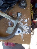
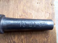
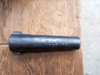
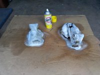
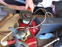
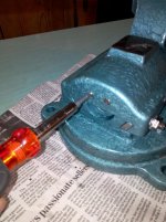
1. Break and scrape the plaster off. I forgot to mention that I taped up the bushing to keep the inner diameter clean. After that, I did a lot of hand sanding and filing on the top side, to get the new foot to look as close as I can to the others.
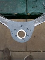
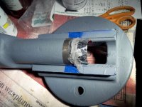
2. On the bottom side, the original feet had pads cast into them. I sanded down the bottom of the new foot and drilled some blind holes to anchor a new molded pad.
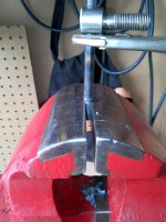
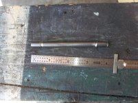
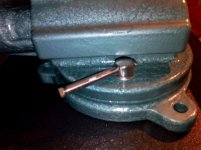
3. I cut a piece of cardboard to the shape of the foot pad and placed a 1/2" bolt in the bushing. I applied a thin coat of grease to the bolt and the top of my cardboard mold to keep the Devcon from sticking to them.
4. I mixed & poured in the Devcon on the bottom of the foot to make the pad.

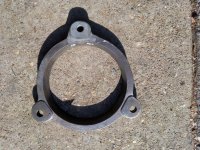
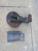
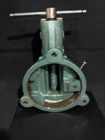
5 & 6. After removing the cardboard mold & bolt, I sanded & filed the foot pad to get it to look as close as I can to the other feet. These 2 pictures are how the base looks before priming.

Now, off to the rest of the vise!
 

Attachments

  • 9.BASE FIX7.jpg
    9.BASE FIX7.jpg
    144.9 KB · Views: 35
  • 10.BASE FIX8.jpg
    10.BASE FIX8.jpg
    141.9 KB · Views: 40
  • 11.BASE FIX9.jpg
    11.BASE FIX9.jpg
    148.4 KB · Views: 38
  • 12.BASE FIX10.jpg
    12.BASE FIX10.jpg
    147.9 KB · Views: 36
  • 13.BASE FIX11.jpg
    13.BASE FIX11.jpg
    141.5 KB · Views: 38
  • 14.BASE FIX12.jpg
    14.BASE FIX12.jpg
    143.7 KB · Views: 35
To avoid these ads, REGISTER NOW!

Mark in Indiana

Well-known member
Joined
Aug 11, 2010
Messages
3,057
Location
Southern Indiana
DISASSEMBLY

Now that the base is finished, it's time to disassemble the rest of the vise. Taking a reverse movement vise apart is as easy as a standard movement vise. All that needs to be done is to remove the 3 screws/nuts n the side, remove the 2 spindle nut screws at the back end, open the jaw far enough to remove the spindle from the nut, and slide the dynamic jaw away from the stationary jaw. As with anything, don't gorilla it with a BF hammer and a BF pry bar. I've heard of some guys who have broken the side of the dynamic jaw body.

1st Picture: The bodies easily came apart.

2nd Picture: All of the disassembled pieces.

3Rd & 4th Picture: The spindle nut; Third picture shows the model number positioned on the bottom. Fourth picture shows some other stamped letters. I don't know what they mean.

5th Picture: The original paint was preserved. Looks like Rustoleum Hammered Verde.
 

Attachments

  • 18.FPU9 COLOR.jpg
    18.FPU9 COLOR.jpg
    146.8 KB · Views: 16
  • 17.1.FPU VISE NUT TOP.jpg
    17.1.FPU VISE NUT TOP.jpg
    147.9 KB · Views: 18
  • 17.FPU VISE NUT BOTTOM.jpg
    17.FPU VISE NUT BOTTOM.jpg
    147.4 KB · Views: 17
  • 16.FPU VISE DISASSEMBLED.jpg
    16.FPU VISE DISASSEMBLED.jpg
    144.2 KB · Views: 16
  • 15.FPU7.jpg
    15.FPU7.jpg
    146.5 KB · Views: 16

Mark in Indiana

Well-known member
Joined
Aug 11, 2010
Messages
3,057
Location
Southern Indiana
PAINT PREPARATION

As this vise went through an aerosol overhaul, there were many coats of paint to deal with:

1st Picture; The stationary and dynamic jaw bodies are sprayed down with EZ-Off.
I let it soak for 5 – 6 hours because of chemical damage concerns. 8 – 10 hours will be fine and save some work with the wire wheel.

2Nd Picture: EZ OFF has been wiped off. Ready for the wire wheel.

3nd Picture: After some time on with the wire wheel, the bodies are all cleaned up. Oops! The edge of spindle cover, on the stationary jaw body looks damaged. There was some discussion about this on the Vise Repair 101 thread. Either that jagged edge was like that from the factory or it ended up on the wrong end of a BFH.

4rd Picture: I decided to mask & prime all of the bare metal to prevent flash rust.

5Th Picture: Place some HVAC aluminum tape under the spindle cover as a dam and apply JB Weld to the edge.

6Th Picture: JB Weld has been poured. After cure time and some sand paper work, the repair will be complete,
 

Attachments

  • 25.FPU SPINDLE COVER REPAIR4.jpg
    25.FPU SPINDLE COVER REPAIR4.jpg
    141.7 KB · Views: 21
  • 24.FPU VISE SPINDLE COVER REPAIR3.jpg
    24.FPU VISE SPINDLE COVER REPAIR3.jpg
    147 KB · Views: 20
  • 23.FPU VISE SPINDLE COVER REPAIR2.jpg
    23.FPU VISE SPINDLE COVER REPAIR2.jpg
    142.4 KB · Views: 20
  • 22.FPU VISE SPINDLE COVER REPAIR1.jpg
    22.FPU VISE SPINDLE COVER REPAIR1.jpg
    140.4 KB · Views: 22
  • 21.FPU VISE PAINT CLEAN3.jpg
    21.FPU VISE PAINT CLEAN3.jpg
    146.1 KB · Views: 20
  • 20.FPU VISE PAINT CLEAN2.jpg
    20.FPU VISE PAINT CLEAN2.jpg
    144 KB · Views: 19
  • 19.FPU VISE PAINT CLEAN1.jpg
    19.FPU VISE PAINT CLEAN1.jpg
    140.8 KB · Views: 19

Mark in Indiana

Well-known member
Joined
Aug 11, 2010
Messages
3,057
Location
Southern Indiana
PAINT DAY!

It's a nice hot, sunny day. Perfect for vise painting.

1st Picture: The paint & clear coat that will be used.

2nd Picture: All the pieces are hanging around waiting to dry.

3rd Picture: Normally, my restorations include painting the embellishments a separate color from the body. I chose red & white for the FPU embellishment, which are the colors of the Polish flag.

4th Picture: WARNING! Rustoleum Painter's Touch 2X clear coat will react with Rustoleum Hammered paint, causing it to coarsely wrinkle like a Kennedy tool box finish, when the parts to clear coated are hot. I found this out by accident on a previous restoration. That's OK! The first coat of clear went on hot parts. After drying, I took them to a cool room, let the parts cool and sprayed on the rest of the clear coats.

Summary: This took several days to complete. There are 3 coats of Verde Green color and a S-Load of clear coats on this vise. Every coat went on first thing in the morning and last thing in the evening.

A few days for complete drying & cure time will take us to the vise reassembly.
 

Attachments

  • 29.FPU VISE PAINT2.jpg
    29.FPU VISE PAINT2.jpg
    151.5 KB · Views: 29
  • 28.RESTORED FPU15.jpg
    28.RESTORED FPU15.jpg
    139.3 KB · Views: 42
  • 27.FPU VISE PAINT DAY.jpg
    27.FPU VISE PAINT DAY.jpg
    149.8 KB · Views: 22
  • 26.FPU VISE PAINT.jpg
    26.FPU VISE PAINT.jpg
    125.2 KB · Views: 25

Mark in Indiana

Well-known member
Joined
Aug 11, 2010
Messages
3,057
Location
Southern Indiana
One of the major challenges of this vise is that the swivel base handle is missing. Fortunately, it's just the handle alone, not the bolt or the base stop (pulled up into the base to prevent movement when tightened).

Using a swivel base handle from a 150mm Bison-Bial vise as a model:
The handle is 7mm dia. Unfortunately, I couldn't fine a 7mm, plain bolt, with a long enough shank to make the handle. To solve that problem, I drilled out the hole in the vise's swivel base lock bolt (where the handle goes) and used a 5/16"-18 x 6", grade 8 machine screw. After that, I cut off the hex head and cut the threaded section off.

1st Picture; There is a groove cut at each end of the handle. Since I don't have access to a surface grinder with a spin jig, I secured an electric drill in my Parker vise and powered it using a variable voltage transformer (variac) to slow the drill down. Since the drill uses a brushed motor, this won't harm it. To cut the grooves in the ends, I used an*@#$angle*@#$grinder*@#$with a cut-off wheel.

2nd Picture; Finished with my "spin grinder". Now the grooves can be cleaned up with an aggressive wire wheel.

3rd Picture; The ends need to be flattened, horizontally in line with the shaft. Since this shaft came from a grade 8 bolt, it will need to be heated cherry red to shape the ends.*@#$

4th Picture; Immediately after heating an end, I crimped it with my Parker vise. This vise has smooth jaw faces and is heavy enough to do the job. Before crimping the second end, I placed the shaft in the hole of the swivel base lock bolt.
Note; I know that it's a NO-NO to use a vise as a press. However, cherry red steel is fairly soft, and the crimp wouldn't be as accurate by me, if I used a*@#$hammer*@#$& anvil.

5th Picture; New handle with the old one. I trimmed the handle ends, cleaned off burrs with a wire wheel and polished. At this time it's ready to be clear coated.

Side note about this task for this restoration:
As stated before, one of the standards for this restoration is that I wanted to use methods that didn't involve special equipment that's normally not found in a homeowner's garage (mill, lathe, welders, etc), to show that specialized equipment may not be necessary for a challenging restoration or repair. Because of the hardness of the bolt that I used to make the handle, I had to use an oxygen/acetylene torch in forming the ends. This is the only part of this restoration that I used specialized equipment on.


Now...Time for the vise reassembly!
 

Attachments

  • 34.FPU VISE BASE HANDLE5.jpg
    34.FPU VISE BASE HANDLE5.jpg
    154.4 KB · Views: 25
  • 33.FPU VISE BASE HANDLE4.jpg
    33.FPU VISE BASE HANDLE4.jpg
    142.2 KB · Views: 30
  • 32.FPU VISE BASE HANDLE3.jpg
    32.FPU VISE BASE HANDLE3.jpg
    142.2 KB · Views: 25
  • 31.FPU VISE BASE HANDLE2.jpg
    31.FPU VISE BASE HANDLE2.jpg
    144 KB · Views: 22
  • 30.FPU VISE BASE HANDLE1.jpg
    30.FPU VISE BASE HANDLE1.jpg
    107.1 KB · Views: 28

Mark in Indiana

Well-known member
Joined
Aug 11, 2010
Messages
3,057
Location
Southern Indiana
REASSEMBLY

Now that the paint/clear coat has dried and the masking tape has been removed, it's time to reassemble this vise.

1st Picture: Stationary body is mounted to the base.

2nd Picture: The gib. Before attaching the dynamic body the stationary one, I will have to install the gib and adjustment screws. This is used to adjust the dynamic jaw for precise movement. The adjustment screws must be loose until the reassembly is complete. I will also have to set the spindle nut in place and install the two retaining screws.

For aesthetics, clear silicon grease is applied to the polished metal slides. EP2 bearing grease is applied to the spindle. The dynamic jaw body will then be installed on the body, spindle with retainer installed and the vise will need to be opened & closed several times to break away any overspray and ensure smooth movement.

3rd Picture: *The spindle nut retaining screws are screwed in so the screw tops are flush with the body and the spindle nut will somewhat float. If the screws are too tight, it will lock in the spindle nut and cause the dynamic jaw to bind.

4th Picture: *The 3 gib adjustment screws. Starting with the center one, tighten it down all the way. Then loosen it ¼ turn. Tighten the jamb nut. Do this with the two outer gib adjustment screws. You will notice the washers under the jam nuts. They are there to protect the paint.

* NOTE: If there is a reverse movement vise or FPU expert out there, please let me know if I calibrated this vise correctly.

5th Picture: Oops! The swivel base lock bolt is too tall to allow movement of the dynamic jaw body. This is because I added a bushing at the bottom of the lock bolt to protect the paint from the lock bolt when tightening. This is a feature that I add to all of my restorations. The bushing raised the bolt too much to allow dynamic jaw movement.
I will have to grind a little off the top & bottom of the bolt.

6th Picture: After some time with Mr. Grinder, the swivel base lock bolt is short enough to allow dynamic jaw movement.

7thPicture: Bottom of the vise base. I like how the 3 iron blocks lock into the inside bevel of the base at 3 points, when the lock bolt is tightened. IMO: Although not as solid as the drum brake swivel base lock design used on Chas. Parker vises, it's much better than the normal carriage bolt/nut swivel base lock design.
 

Attachments

  • 41.RESTORED FPU14.jpg
    41.RESTORED FPU14.jpg
    143.5 KB · Views: 24
  • 40.RESTORED FPU SWIVEL LOCK.jpg
    40.RESTORED FPU SWIVEL LOCK.jpg
    134 KB · Views: 19
  • 39.FPU VISE ASSEMBLY2.jpg
    39.FPU VISE ASSEMBLY2.jpg
    132.6 KB · Views: 17
  • 38.FPU VISE ADJUSTMENT2.jpg
    38.FPU VISE ADJUSTMENT2.jpg
    147.5 KB · Views: 24
  • 37.FPU VISE ADJUSTMENT1.jpg
    37.FPU VISE ADJUSTMENT1.jpg
    137.7 KB · Views: 23
  • 36.FPU VISE GIB.jpg
    36.FPU VISE GIB.jpg
    145.5 KB · Views: 20
  • 35.FPU VISE ASSEMBLY1.jpg
    35.FPU VISE ASSEMBLY1.jpg
    144 KB · Views: 27

Mark in Indiana

Well-known member
Joined
Aug 11, 2010
Messages
3,057
Location
Southern Indiana
EPILOGUE

What I hope you all have been waiting for: Here is the fully restored FPU vise.


These pictures show different areas of the completed vise restoration.
You will notice that the blemishes on the anvil surface and the jaw tops have been preserved. I purposely do this on all of my restorations because they are part of the vise's character.


Summary: I hope that this thread were informative.
This vise was a privilege to restore and document. It's an honor to share it here.
Was this financially responsible? NO! However, it's more satisfying, cheaper and less frustrating than a golf outing. ;)


Happy Trails! Thanks for reading.
 

Attachments

  • 48.RESTORED FPU13.jpg
    48.RESTORED FPU13.jpg
    133.5 KB · Views: 28
  • 47.RESTORED FPU11.jpg
    47.RESTORED FPU11.jpg
    140.3 KB · Views: 29
  • 46.RESTORED FPU10.jpg
    46.RESTORED FPU10.jpg
    133.8 KB · Views: 28
  • 45.RESTORED FPU8.jpg
    45.RESTORED FPU8.jpg
    140.4 KB · Views: 25
  • 44.RESTORED FPU7.jpg
    44.RESTORED FPU7.jpg
    140.5 KB · Views: 28
  • 43.RESTORED FPU4.jpg
    43.RESTORED FPU4.jpg
    130.5 KB · Views: 32
  • 42.RESTORED FPU2.jpg
    42.RESTORED FPU2.jpg
    135.7 KB · Views: 33
Last edited:

ed4banger

Well-known member
Joined
May 28, 2016
Messages
470
Location
Virginia
Here is a 4.5" Wilton Bullet I just refurbished.

It was initially pretty hard to look at. Mostly covered in dirt and a thick layer of paint.

_DSC0756cs9_zpspvhy39jj.jpg


_DSC0759cs9_zps5ua0vohj.jpg


Upon inspection, everything was working pretty good. Turned out to be an old one, with slide date of 11/45.

http://i1224.photobucket.com/albums/ee363/40plymouth/_DSC0755cs9_zpstjvexkpk.jpg

Wire wheel cleaned most up, finished up with a soda blaster. The casting was much rougher than I would have expected.

_DSC0767cs9_zpsibikbeqt.jpg


_DSC0766cs9_zpsp0khkarf.jpg


I decided, since the nut and screw were rust free, to not remove the nose on this one, and just cleaned inside with kerosene and a variety of copper brushes and bottle brushes. When dry, I coated the interior of the casting with a spray-on wax.

_DSC0771cs9_zpsj5kuxm1b.jpg


Handle was bent pretty good, and was going to go with a new one, but it straightened up pretty good, and working it good with 400 and then 800 grit wet sand paper really made it feel nice to the touch, so kept it.

_DSC0772csp_zpsgi4amlri.jpg


_DSC0773cs9_zps4ocfqhzg.jpg


Also had decided to replace the jaws, so I bought a set, which were very well made, but they did not retain the factory jaw pin which I wanted to keep. Cleaned up originals and reinstalled. A little ruff, but I think they add a little character.

_DSC0775cs9_zpsabzcoyqa.jpg


I decided not to fill any dings or damage, as I kind of like the way it shows its use/abuse.

_DSC0774cs9_zpsayldkz6h.jpg


Doing these kind of write-ups is not my thing, but I just wanted to show it off a little.
 

Mark in Indiana

Well-known member
Joined
Aug 11, 2010
Messages
3,057
Location
Southern Indiana
ed4banger,
Cool! I have an early 4" Wilton with the same date stamp.

Outlaw,
Thanks for the kind words. I hope my restoration will encourage broken vise owners to restore them, instead of scrapping.
 

Imazagi

Member
Joined
Jun 13, 2016
Messages
23
Location
Austria
Summary: I hope that this thread were informative.

Oh yes it was. I'm a new member here, just setting up my garage and I bought what turned out to be an FPU vise with 10mm jaws for €25 today, very similar to yours. Your detailed posts coudn't come at a better time for me.

One of my jaws is broken, I'll start looking for a new set today. It looks like these are fine tools and it will be worth it.
Thanks again for sharing!
 
Last edited:

Imazagi

Member
Joined
Jun 13, 2016
Messages
23
Location
Austria
To show you how informative your post was, here's some pictures. As I said, I joined a couple of days ago and bought the FPU yesterday. The ad said €40 with a broken jaw, I got it for 25.
The jaw set screws were moving freely. The swivel screw needed some persuasion, but also moved after a couple of blows.
After googling "FPU vise" I came right to your post and had my work for today cut out (between painting my Miata's new front wing). Anyway, to the pics.

As bought:
1.jpg


Broken jaw, I'm looking for a new set. Anyone know a good Euro source? They're 100x20mm with 60mm hole center distance:
2.jpg


After stripper, wire wheel and a wash:
3.jpg


Ready for paint. Yes, I forgot to mask the jaws on the movable part and will sand them down again. You can see that the edge of the spindle tube is also jagged on this one. I guess it's an FPU feature:
4.jpg


After 2 coats of primer and 3 coats of paint:
5.jpg


Adding some detail. I planned to do it in black, but when I went to my paint stash, the first can I grabbed was this one - I really like the contrast:
6.jpg


Assembled with bearing grease, everything's moving fine, all ready. Matches my windows which I painted last week. I need another bench now, this one is too small for this 19.1kg piece:
8.jpg


Thanks for reading!
 
Last edited:

Imazagi

Member
Joined
Jun 13, 2016
Messages
23
Location
Austria
Sorry, I just noticed, looks like this forum doesn't play well with imgur. I'll re-host them later.

Edit: Heh, my 10 year old photobucket account still works. Should be fixed now.
 
Last edited:

Outlawmws

Well-known member
Joined
Aug 9, 2011
Messages
39,131
Location
The Badlands
Zagi, great job! Not sure if you know this, but that looks a lot like John deer Green and Yellow.
 
Last edited:

zeet

Well-known member
Joined
Jun 13, 2013
Messages
196
Location
Southern California
"Assembled with bearing grease, everything's moving fine, all ready. Matches my windows which I painted last week. I need another bench now, this one is too small for this 19.1kg piece"

Nice job! :beer:
 
To avoid these ads, REGISTER NOW!

Imazagi

Member
Joined
Jun 13, 2016
Messages
23
Location
Austria
Thank you for the nice words -

Mark No, the alu jaws are just hardware store items. I sent out a mail to Bison Bial Germany to see if they can supply me with original steel jaws, otherwise I'll have to find similar pieces.

Outlaw Now that you say it, it's obvious! Around here, most old tractors come from Steyr (or Porsche), but there are some John Deeres around.
 

bulletpruf

Well-known member
Joined
Nov 28, 2013
Messages
10,929
Location
San Antonio
So I noticed my Morgan 60 has a bit of slop in the vise nut. One of the problems is that the prior owner must have broken or lost the pin that holds the nut in place. He replaced it with a bolt that was jammed in the hole pretty tight. I removed it, but it took some time and I broke a few left handed drill bits in the process.

Here she is as-purchased:


And here's the vise nut - you'll notice that it doesn't seem to be worn out where it slides into the static jaw -


And here's the slot width - you'll notice that it's about .13" wider than the vise nut.


And here's the nut installed - arrows pointing to the area where there appears to be plenty of clearance.


I e mailed Morgan and here's what they said:

"Yes that is the correct nut. No don't shim it, its designed to have a loose fit. What is wrong with your nut or screw? When replacing the nut and or screw, we also need to know the city name on your vise, Chicago, Aurora, or Milwaukee."

I'm surprised that it's loose. More surprised for Morgan to tell me it's supposed to be this loose.

Anyway, this is not a concours restoration; just want to have a nice useable vise. I was thinking of something that's semi-permanent but reversible -- maybe pouring some molten lead into the gap to tighten it up.

Your thoughts?

Thanks!

Scott
 
OP
D

drivesitfar

Well-known member
Joined
Oct 23, 2013
Messages
35,999
Location
Pacific Northwest
BP: i think i'd go with Morgan's advise and not shim the sides. putting the pin in and removing any slop with the sleeve holding the screw in the dynamic is where you should be able to correct the extra slop. i'm not 100% on this so i'm willing to hear other member's thoughts.

for big vises and your 142 pound Morgan is a BIG UN your screw can probably break the vise nut if you have it too firm in the slot is probably why Morgan wants it to be a little loose. ok?

ZAGI: love the colors and the restoration. I also love FPU Bison vices. WELL DONE!!
 

CRSINMICH

Well-known member
Joined
Aug 15, 2015
Messages
2,396
Location
Southeastern Michigan
bulletproof: I'm not a machinist so take this for what it is - personal experience. Twice lately I have had to deal with issues from a spindle nut not fitting properly in its dovetailed slot but the opposite problem from you. They fit too tightly. The worst one was a Reed with piss poor machining (Sorry about the heresy guys). The nut was wedged in so tightly that it restricted the movement of the spindle and made it hard to back the slide all the way out. I was finally able to get the nut out by gently "tapping" it with a BFH. I had to file the dovetail of the nut and the interior dovetail slot to get things to the point that the nut would slide into and out of the slot. The slide moves freely now.

The other vise was a Yost. The problem there was that the nut was cemented into the slot by 90 years of industrial crud and sludge. Once that was cleaned off everything worked fine.
 
Last edited:

Mark in Indiana

Well-known member
Joined
Aug 11, 2010
Messages
3,057
Location
Southern Indiana
BP,
Great detailed pictures.
I agree with Drives. What he said about taking out the slop is a good way to reduce the problem.

IMO: I wouldn't sweat it too much. Having a little slop in the movement of a bench vise is OK. If it was a milling machine vise, then there would be a problem.
 

bulletpruf

Well-known member
Joined
Nov 28, 2013
Messages
10,929
Location
San Antonio
BP,
Great detailed pictures.
I agree with Drives. What he said about taking out the slop is a good way to reduce the problem.

IMO: I wouldn't sweat it too much. Having a little slop in the movement of a bench vise is OK. If it was a milling machine vise, then there would be a problem.

Thanks for the details. Can someone explain to me what is meant by "putting the pin in and removing any slop with the sleeve holding the screw in the dynamic is where you should be able to correct the extra slop"?

Putting the pin in is easy enough. I understand what the sleeve is that holds the screw in the dynamic. What I don't know is how you would use this sleeve to remove slop.

Any info here?

thanks

Scott
 
OP
D

drivesitfar

Well-known member
Joined
Oct 23, 2013
Messages
35,999
Location
Pacific Northwest
BP: what i meant by taking out the slop with the sleeve is if you can get it tight up against the inside of the dynamic so that when you start turning the handle the dynamic starts to move. a lot of vises especially the older ones that have a lot of wear you can turn the handle maybe up to a quarter turn before the jaw starts moving.

some of the guys just put thrust bearings on the opposite side of the dynamic from the sleeve between the handle's head and dynamic to tighten it up and remove the slop. hope i described that correctly and maybe a few of the guys that have done this have a few pictures to show you. ok?
 

thepipe

Well-known member
Joined
May 17, 2015
Messages
88
Location
Southern NJ
I tried searching, but was quickly overwhelmed by the volume of information. Somebody please point me in the right direction...

I purchased a Snap On branded Wilton 1740 on Craigslist today. I need the two rubber washers that go on the spindle handle and two Snap On name plates. I'm finding lots of vinyl stickers on eBay, but these name plates are metal. They measure 4 inches x 1-3/8 inches and are adhered to the vise by double-sided sticky tape. Where do I need to look for these and how much should I pay? Thanks.
 

bulletpruf

Well-known member
Joined
Nov 28, 2013
Messages
10,929
Location
San Antonio
I tried searching, but was quickly overwhelmed by the volume of information. Somebody please point me in the right direction...

I purchased a Snap On branded Wilton 1740 on Craigslist today. I need the two rubber washers that go on the spindle handle and two Snap On name plates. I'm finding lots of vinyl stickers on eBay, but these name plates are metal. They measure 4 inches x 1-3/8 inches and are adhered to the vise by double-sided sticky tape. Where do I need to look for these and how much should I pay? Thanks.

I don't know if he has them, but best place for Wilton parts is http://www.wiltonviseparts.net - owner is a member here. I've done business with him - his stuff is top notch.

Welcome to GJ!

Scott
 

thepipe

Well-known member
Joined
May 17, 2015
Messages
88
Location
Southern NJ
I don't know if he has them, but best place for Wilton parts is http://www.wiltonviseparts.net - owner is a member here. I've done business with him - his stuff is top notch.

Welcome to GJ!

Scott

Hey, Scott:
Thanks for the welcome, but I must confess to being a lurker here for years. What a resource this group is!

Speaking of resources, the link you provided is informative and I thank you for it. No Snap On labels are listed there, though, only Wilton.

I had been hoping someone had a set in their toolbox gathering dust.
 

CRSINMICH

Well-known member
Joined
Aug 15, 2015
Messages
2,396
Location
Southeastern Michigan
Hey, Scott:
Thanks for the welcome, but I must confess to being a lurker here for years. What a resource this group is!

Speaking of resources, the link you provided is informative and I thank you for it. No Snap On labels are listed there, though, only Wilton.

I had been hoping someone had a set in their toolbox gathering dust.

pipe: The guys on the block grinder thread have found a way to have their stickers and plates reproduced. It might be useful for you too. Here's a link to the thread at about the time they were discussing this. Follow it backward and forward for a few pages and you might find something. Good luck and welcome.

http://www.garagejournal.com/forum/showthread.php?t=157794&page=419
 

thepipe

Well-known member
Joined
May 17, 2015
Messages
88
Location
Southern NJ
Thanks for what turned out to be a great link. It turns out that the fella that makes these reproduction plates (simply INCREDIBLE work, BTW) lives in the next town over from me. I just PM'd him and can't wait to hear if he can do them.
 
Last edited:

Shiftless

Well-known member
Joined
Mar 9, 2014
Messages
14,486
Location
East Bay SFO
Thanks for what turned out to be a great link. It turns out that the fella that makes these reproduction plates (simply INCREDIBLE work, BTW) lives in the next town over from me. I just PM'd him and can't wait to hear if he can do them.

For the benefit of all of us here, please post the identity of the guy wo makes reproduction stickers. I for one will note it in a permanent part of my memory.
Thanks! :thumbup:
 

Watsondog

Active member
Joined
Mar 6, 2016
Messages
34
Location
Minnesota
Gang!
What's the best way to clean up this 5" FPU while keeping the paint and patina in tact?
uploadfromtaptalk1467202349304.jpguploadfromtaptalk1467202376302.jpgBLO over the top for a finish coat?

Sent from my SM-G900V using Tapatalk
 
OP
D

drivesitfar

Well-known member
Joined
Oct 23, 2013
Messages
35,999
Location
Pacific Northwest
WD: you can clean up your FPU bison vise (one of my favorites BTW) a number of ways. put WD 40 or mineral spirits on a rag and use some elbow grease. if you are trying to leave the original paint you can use Simple green, but don't leave the SG on very long because it might take the paint off. yes BLO is maybe my favorite option to put on a vise and several coats work best. also know that you'll need to put more BLO on every few months more or less depending on conditions in your shop to keep the rust at bay. nice find

PIPE: I actually like the Snap on decals you could buy on Ebay that look great with a bright green paint job, but if PUP can make you a metal one that you like i'm the first one to ask you to post pictures because that might be very cool because he does a fantastic job on the Block grinder labels.
 

Outlawmws

Well-known member
Joined
Aug 9, 2011
Messages
39,131
Location
The Badlands
Watson, if you want to preserve the paint, and lose the rust, probably start with Evaporust. then, being careful on the original paint, SG on what appears to be spilled paint?

Other than that WD-40 and a rag, elbow grease, possibly a clay block if there is paint spatter?
 
Last edited:
To avoid these ads, REGISTER NOW!
Top Bottom