To avoid these ads, REGISTER NOW!

VISE REPAIR 101 all vise repairs, lubricants, sources for parts and the tricks to fix

cajunfirehawk

Well-known member
Joined
Nov 29, 2011
Messages
2,566
Location
Ms Gulf Coast
Stop what your doing, buy a deburring wheel, now. Don't wait like i did, what a great tool. This one is a Norton convolute, medium i recall. Even snagged a new to me craftsman block on CL to run it. The polishing in this pic took me only a few minutes
Sent from my iPhone using Tapatalk
Pic and model? :bowdown:
 
To avoid these ads, REGISTER NOW!

scooternut

Well-known member
Joined
Jul 31, 2013
Messages
684
Location
Pittsburgh, PA
The pic above shows the wheel in the background. This is what i ordered, but holy price!! I think i grabbed it on sale for $50... But i really miss ENCO deals.
3a985010c24e7d9552bd3404d403d091.jpg


Sent from my iPhone using Tapatalk
 

Attachments

  • 3a985010c24e7d9552bd3404d403d091.jpg
    3a985010c24e7d9552bd3404d403d091.jpg
    155.7 KB · Views: 0

G20-Budo

Well-known member
Joined
May 31, 2013
Messages
987
Location
Chandler, AZ
The pic above shows the wheel in the background. This is what i ordered, but holy price!! I think i grabbed it on sale for $50... But i really miss ENCO deals.
3a985010c24e7d9552bd3404d403d091.jpg


Sent from my iPhone using Tapatalk

I've seen the results of these wheels..but didn't realize the price.. I'm interested in one, but will probably wait til a deal pops up. $85 is a bit much.

Thanks for the info!
 

Attachments

  • 3a985010c24e7d9552bd3404d403d091.jpg
    3a985010c24e7d9552bd3404d403d091.jpg
    35.5 KB · Views: 0

LG63

Well-known member
Joined
Sep 7, 2012
Messages
1,003
I've seen the results of these wheels..but didn't realize the price.. I'm interested in one, but will probably wait til a deal pops up. $85 is a bit much.

Thanks for the info!

Try the 3M Scotch Brite version at Zoro, item G1719015
About $40 if you can catch a 20% off code.
 

Roberts210

Well-known member
Joined
Dec 21, 2015
Messages
3,177
Location
Missouri
I bought this old baby in late Oct. and have been working on it as time permitted. Got it for $30. Yes it's only got one jaw insert and that one is welded to the dynamic. :eyecrazy:

When the guy advertised it on CL he said it, "used to be a Wilton". That intrigued me and I went to look at it.

164333732.jpg


The static had been welded to the base on both sides. I very carefully ground the welds out with an angle grinder using a well worn 1/4" wheel and then a cut off blade.

To remove the welded insert I first made deep cuts into it with a cutoff blade in my angle grinder, removing most of the mass of it. Then I used a cold chisel and hammer to pry and push the remaining thin pieces away from the casting. Hardest part was removing the broken off 1/4" screws that held the original jaws in place. I drilled 'em and then used an easy-out to remove them.

164333735.jpg


I've spent about $80 on parts for it.

164827550.jpg


Sorry for the fuzzy pictures.

164827561.jpg


164827562.jpg


164827563.jpg
 

scooternut

Well-known member
Joined
Jul 31, 2013
Messages
684
Location
Pittsburgh, PA
e13699c94a0a73d46fc4ec91f30858ec.jpg
8c6245777d4071503fe253f90fdc635b.jpg
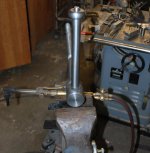
Not completely sure what I'm doing, but I'm giving a go at press fit and peen for a replacement vise handle.

I have great measurement tools, though my skills with them are suspect. Lathe work is being performed on a mini lathe by harbor freight.


Sent from my iPhone using Tapatalk
 

Attachments

  • 8c6245777d4071503fe253f90fdc635b.jpg
    8c6245777d4071503fe253f90fdc635b.jpg
    831.1 KB · Views: 0
  • e13699c94a0a73d46fc4ec91f30858ec.jpg
    e13699c94a0a73d46fc4ec91f30858ec.jpg
    838.8 KB · Views: 1

scooternut

Well-known member
Joined
Jul 31, 2013
Messages
684
Location
Pittsburgh, PA
Any suggestions to the length of protrusion past the ball prior to peening?

My hole is 3/8 with a bit of chamfer on top of ball, the goal is a bit of a beginner press fit.


Sent from my iPhone using Tapatalk
 

kwoswalt99

Well-known member
Joined
Oct 24, 2015
Messages
701
Location
Detroit
Any suggestions to the length of protrusion past the ball prior to peening?

My hole is 3/8 with a bit of chamfer on top of ball, the goal is a bit of a beginner press fit.


Sent from my iPhone using Tapatalk

More than you need. It can be ground down.
 

KMScott

Well-known member
Joined
Feb 14, 2012
Messages
4,643
Location
Daufuskie Island, South Carolina
Any suggestions to the length of protrusion past the ball prior to peening?

My hole is 3/8 with a bit of chamfer on top of ball, the goal is a bit of a beginner press fit.


Sent from my iPhone using Tapatalk

I like at least 3/8 minium before peening, having a slip fit or even a light press fit is good, any gap causes oxide and can be seen in the finished job. The heavier the chamfer is the more petruding you need. I use 3/8 to 7/16 diameter like you did on most of my handles. GETRIDAONE had a good idea with the flap wheel, I use a 1" ribbon sander and finish up with 120 grit sandpaper either by hand or with a DA then final finish is with Maroon Scotch Brite. Good luck scooternut, show us your finished handle.
 

Attachments

  • Handle Fabrication 07-2014 (3).jpg
    Handle Fabrication 07-2014 (3).jpg
    119.4 KB · Views: 69
  • Handle Fabrication 07-2014 (7).jpg
    Handle Fabrication 07-2014 (7).jpg
    90.9 KB · Views: 67
  • Adding a knob to a handle (3).jpg
    Adding a knob to a handle (3).jpg
    139.5 KB · Views: 64
  • Making Knobs (13).jpg
    Making Knobs (13).jpg
    79.8 KB · Views: 59
Last edited:

scooternut

Well-known member
Joined
Jul 31, 2013
Messages
684
Location
Pittsburgh, PA
Thank you. I didn't have any torches in the shop to develop that kind of heat.


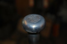
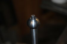
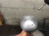
I went with a pretty tight press fit, heat and some hammer persuasion. I left about .1 proud of the ball, then just went about hammering with a nice dead blow peen. It seemed to form in there nicely, time will tell. Cleaned it up with sandpaper and a deburring wheel. A few hammer marks went a little deep so I just left them in.
IMG_0466.JPGIMG_0468.JPGIMG_0477.JPGIMG_0485.JPGIMG_0488.JPG
 
Last edited:

larry4406

Well-known member
Joined
Jan 27, 2006
Messages
19,516
Location
Northern Virginia
Scooternut - nice job! Any reason you simply did not plan for an intereference fit? I recently installed a pressed fit wrist pin by putting the pin in the deep freeze for a week (0F) and heated the piston to about 250F in an oil bath in a coffee can on the grille. Slipped right in nice.
 

KMScott

Well-known member
Joined
Feb 14, 2012
Messages
4,643
Location
Daufuskie Island, South Carolina
Nice job Scooter, you know Wilton did theirs cold too, but they used a punch press as my guess. I have seen new old stock handles from Wilton with witness lines of a form die and assume they did it cold. Yours looks like it is new. The next one will be easier.
 

kwhunter

Well-known member
Joined
Oct 9, 2016
Messages
61
Location
@home
Bought an used Wilton C1 recently, used but in pretty good shape:

_MG_4422_zpsh8gexjls.jpg


Noticed that one of the dowels retaining the end piece was half out

_MG_4420_zpsf8zqegtg.jpg


Anyway, proceeded to take the vise apart for cleanup. Everything went smooth up until a point: removing the end piece; the protruding pin slid out easy, however I had trouble knocking the other one out with the parallel punch; came out half, and was bent; I had to pull it with a vise grip. The end piece and nut came finally out and then... horror: the end piece wall was broken on the axis of the vise.

_DSC2519_zpsjxnvplnc.jpg


_DSC2520_zpsjdfdqfoc.jpg


The vise had no signs of being tampered with, the 2nd pin hasn't been removed since the vise left the factory in the 70s (date code is 4-80). At closer inspection I found that the nut was not seated properly in the end piece:

_DSC2532_zpsfirhsrro.jpg


_DSC2531_zpsdsrzqiee.jpg


The tabs on the end of the nut were seated in between the notches in the end piece. When I seated the nut right, I found this:

_DSC2527_zpszib9u9xf.jpg


The nut was overhanging in the vise, being held only by the pins; over time, pressure developed on the side of the hole wall in the direction of the pull, cracking it. Eventually, one pin came out and the other pin was bent by the pulling force. The holes in the body and the end piece line up as they should, but in the nut they are off.
Anyway, I will have to re-seat the nut and re-drill the holes; I cannot turn the end piece because it was ground at the factory and will look bad. The holes wall is not broken completely so they can still hold the pin securely; the pull will seat the nut and press the end piece on the vise body, so unless I hammer the end of the spindle (?!) it will work fine. The pins and holes are 0.25", but one hole is a little larger so I am thinking of reaming the holes a tad larger and cut new pins to size.

There is also an issue with the base, it won't lock due to wear. The PO used the centering ring of a spiral wound gasket as a spacer... That is an easy fix.
 
Last edited:

G-ManBart

Well-known member
Joined
Jan 24, 2015
Messages
2,059
Location
Michigan
Anyway, proceeded to take the vise apart for cleanup. Everything went smooth up until a point: removing the end piece; the protruding pin slid out easy, however I had trouble knocking the other one out with the parallel punch; came out half, and was bent; I had to pull it with a vise grip. The end piece and nut came finally out and then... horror: the end piece wall was broken on the axis of the vise.


The vise had no signs of being tampered with, the 2nd pin hasn't been removed since the vise left the factory in the 70s (date code is 4-80). At closer inspection I found that the nut was not seated properly in the end piece:


The nut was overhanging in the vise, being held only by the pins; over time, pressure developed on the side of the hole wall in the direction of the pull, cracking it. Eventually, one pin came out and the other pin was bent by the pulling force. The holes in the body and the end piece line up as they should, but in the nut they are off.
Anyway, I will have to re-seat the nut and re-drill the holes; I cannot turn the end piece because it was ground at the factory and will look bad. The holes wall is not broken completely so they can still hold the pin securely; the pull will seat the nut and press the end piece on the vise body, so unless I hammer the end of the spindle (?!) it will work fine. The pins and holes are 0.25", but one hole is a little larger so I am thinking of reaming the holes a tad larger and cut new pins to size.

There is also an issue with the base, it won't lock due to wear. The PO used the centering ring of a spiral wound gasket as a spacer... That is an easy fix.

That kind of damage is actually pretty common, and is usually caused by the vise being dropped on the spindle. It puts a reverse load on those pins, and they break.

I came up with an easy fix. Braze the holes closed, find a washer a bit smaller than the diameter of the end piece, open up the internal diameter for the nut, braze it over the top of the end piece, then put the end piece in the vise, line it up with the grinder marks from when it was made, redrill the holes for the pins, install new pins and you're done.

I wrote about it here, and added pictures so you can get a better idea what I'm talking about.

http://mivise.com/2017/01/the-vise-that-started-it-all/

This is the short, short version:

 
To avoid these ads, REGISTER NOW!

Smoil

New member
Joined
Jan 18, 2017
Messages
4
Advice on removing main nut pin

I'm working on my first vise restoration and am blown away by the wealth of knowledge on these forums (thanks everyone).

I need to remove the pin which secures the main nut but I'm not sure if I'm supposed to use a hammer and punch to remove the entire "pin" from the bottom or just the pin within the pin highlighted in the attached photos. The vise is an Athol 614 ½.

Hopefully I'm not asking something that has already been answered (read through this thread and several others).

Any advice will be much appreciated.
 

Attachments

  • athol-main-nut-pin-top.jpg
    athol-main-nut-pin-top.jpg
    147.1 KB · Views: 66
  • athol-main-nut-pin-bottom.jpg
    athol-main-nut-pin-bottom.jpg
    149 KB · Views: 61
OP
D

drivesitfar

Well-known member
Joined
Oct 23, 2013
Messages
36,047
Location
Pacific Northwest
KW: too bad about the broken vise nut holder. i usually pull the dynamics out of the wilton bullets i've bought before buying them so i might have a better chance at buying them without that sort of issue, but still you sometimes can't see everything.

as GMAN posted it can be fixed and some of the guy turned the ring 180 degrees and drilled in new holes, but not sure that would work in your situation. heck the parts on yours are almost new so at worse case you could part it out and probably make a few buck.

good luck with your fix and hope you find a good solution.

Smoil: I would guess there maybe isn't a better forum in the world especially for old vises than GJ. i'm guessing a prior own maybe had to drill a hole in a pin to give it some relieve to punch it out from below at one time and maybe just put a cotter pin or a small pin back in the hole. my guess is you should still be able to hit the pin (either one) from below upwards and get it out so you can clean up the vise nut and the inside of your great old Athol vise after that before putting it back together.

there are some of the guys here that work on vises almost daily that might have an easier answer so maybe wait a few hours or a couple days for their answers. also in the meantime it wouldn't hurt to spray in some Kroil or PB blaster to let the pin soak and maybe break up the rust that might be holding it in place.

good luck
 

CrotalusAtrox

Well-known member
Joined
Mar 5, 2016
Messages
796
Location
The Great Southwest
Re: Advice on removing main nut pin

I'm working on my first vise restoration and am blown away by the wealth of knowledge on these forums (thanks everyone).

I need to remove the pin which secures the main nut but I'm not sure if I'm supposed to use a hammer and punch to remove the entire "pin" from the bottom or just the pin within the pin highlighted in the attached photos. The vise is an Athol 614 ½.

Hopefully I'm not asking something that has already been answered (read through this thread and several others).

Any advice will be much appreciated.

You can try and punch out the small pin first then the larger one but I bet that little pin is not going to come out very easy. I would just use a punch and hammer out the whole thing
 

Carla

MEMBER EMERITUS
Joined
Nov 27, 2010
Messages
672
Re: Advice on removing main nut pin

I'm working on my first vise restoration and am blown away by the wealth of knowledge on these forums (thanks everyone).

I need to remove the pin which secures the main nut but I'm not sure if I'm supposed to use a hammer and punch to remove the entire "pin" from the bottom or just the pin within the pin highlighted in the attached photos. The vise is an Athol 614 ½.

Hopefully I'm not asking something that has already been answered (read through this thread and several others).

Any advice will be much appreciated.

I'd think you are seeing an 'optical illusion'......there isn't any small pin in the larger pin, but, rather, the protrusion of the 'nib' or 'teat' left when the pin was parted off has the appearance of a smaller central pin.

Just drive the pin out as usual........ : )

cheers

Carla
 

kwhunter

Well-known member
Joined
Oct 9, 2016
Messages
61
Location
@home
Thanks Drive and G-man, I will do this; however, I will have to drill the vise assembled with the nut since the nut was not seated properly and the holes are offset by as much as 1/8"... probably a Friday afternoon vise
I will also have to fix the inner ring on the base since it won't lock due to wear on the teeth (I do not want to use a spacer like the previous owner)
 

Smoil

New member
Joined
Jan 18, 2017
Messages
4
Thanks for the suggestions and feedback drivesitfar, CrotalusAtrox, and Carla!

I've cleaned up that area a bit more with some brake cleaner and am letting PB Blaster work its magic. Will attempt to knock out that pin in the next day or two.

Hopefully in the near future I'll have post some nice before/after photos to share.
 

G-ManBart

Well-known member
Joined
Jan 24, 2015
Messages
2,059
Location
Michigan
Thanks Drive and G-man, I will do this; however, I will have to drill the vise assembled with the nut since the nut was not seated properly and the holes are offset by as much as 1/8"... probably a Friday afternoon vise
I will also have to fix the inner ring on the base since it won't lock due to wear on the teeth (I do not want to use a spacer like the previous owner)

Just out of curiosity, you're saying the holes in the nut are in the wrong place?
 

Carla

MEMBER EMERITUS
Joined
Nov 27, 2010
Messages
672
I'm saying that, just look at the pictures in the original post.

Well, its a factory error, alright, done by a negligent worker at assembly.....some 'bad news', to be sure.....which should have been replaced on warranty. (the 'defect in workmanship' is ever so obvious)

The 'good news' is that a proper repair is simple and straightforward.

Just braze up the broken part. braze up the incorrectly drilled holes in the 'nut', assemble correctly, with tension drawn up firmly, and re-drill. A braze, correctly done, is more than adequately strong enough for the purpose. If you were located in the S. F. bay area, I'd offer to braze it up for you 'pro bono' as it is a simple, easy job.

As has been noted here previously, the best repair/upgrade is to tap the drilled holes in the main fixed jaw casting, and fit Allen set screws of suitable length, with the ends turned or ground down to the nominal pin size, instead of plain drive pins. This allows for easy disassembly for routine cleaning/oiling.

cheers

Carla
 

kwhunter

Well-known member
Joined
Oct 9, 2016
Messages
61
Location
@home
Well, its a factory error, alright, done by a negligent worker at assembly.....some 'bad news', to be sure.....which should have been replaced on warranty. (the 'defect in workmanship' is ever so obvious)

The 'good news' is that a proper repair is simple and straightforward.

Just braze up the broken part. braze up the incorrectly drilled holes in the 'nut', assemble correctly, with tension drawn up firmly, and re-drill. A braze, correctly done, is more than adequately strong enough for the purpose. If you were located in the S. F. bay area, I'd offer to braze it up for you 'pro bono' as it is a simple, easy job.

As has been noted here previously, the best repair/upgrade is to tap the drilled holes in the main fixed jaw casting, and fit Allen set screws of suitable length, with the ends turned or ground down to the nominal pin size, instead of plain drive pins. This allows for easy disassembly for routine cleaning/oiling.

cheers

Carla

Thanks for the offer.
I never said it is the end of the world... just that it is sad to find such damage due to a negligent job. I am not the original owner and I cannot say when the damage occurred, during warranty or post warranty; I have the end piece welder (or brazed...), will get it back next week.
I think I will go the set screw path, just a question though: should the end piece wall be threaded too, or just the body? The "pin" end of the set screw will hold the nut, obviously
 
OP
D

drivesitfar

Well-known member
Joined
Oct 23, 2013
Messages
36,047
Location
Pacific Northwest
KW: from all the threaded pins the members have been making to improve that not so great design Wilton made they put threads in the static's slide and just ground off the threads on the ends to just set inside the vise nut's holes. there are many many pictures and explanations about this on this thread and sorry i don't know the post #'s off hand. i know VOI, AE NEUMAN, KMScott and several members that did them and posted pictures though if that helps.

good luck
 

kwhunter

Well-known member
Joined
Oct 9, 2016
Messages
61
Location
@home
KW: from all the threaded pins the members have been making to improve that not so great design Wilton made they put threads in the static's slide and just ground off the threads on the ends to just set inside the vise nut's holes. there are many many pictures and explanations about this on this thread and sorry i don't know the post #'s off hand. i know VOI, AE NEUMAN, KMScott and several members that did them and posted pictures though if that helps.

good luck

Thanks Drive, I know that; I'm asking because you can tap just the body, or the body and the end piece assembled, I don't think it makes much of a difference since the end piece is just a holder for the nut.
Besides, in KMScott's blog he taps the body assembled with the end piece and you cannot just make the tap stop at the parting surface.
I think it is ok either way since they won't get taken apart too often.
 

Carla

MEMBER EMERITUS
Joined
Nov 27, 2010
Messages
672
Thanks Drive, I know that; I'm asking because you can tap just the body, or the body and the end piece assembled, I don't think it makes much of a difference since the end piece is just a holder for the nut.
Besides, in KMScott's blog he taps the body assembled with the end piece and you cannot just make the tap stop at the parting surface.
I think it is ok either way since they won't get taken apart too often.

The way I did that, (assuming 1/4" dia pins) was to assemble the vise, and tighten the main screw firmly, to tension the parts in place, then drill both sides with a letter 'F' (.257) drill. I'd then remove the nut, and clamp up the end cap firmly to the fixed jaw casting, with a .257 pin on one side for alignment. Then, I'd tap the other side 5/16-18, through both parts. After putting in a set-screw to maintain alignment on that side, I'd tap the other side.

Then, I'd trim the set-screws to length as needed, and turn that area of the setscrews which enter the nut to .255/.253, a slight clearance in the drilled hole in the nut. (a little bit looser wouldn't hurt anything, as the nut can 'float' a little, but shouldn't bind, as it adjusts its location to suit the main screw. If you don't do turning, you can just grind the tips of the set-screws, spinning them neatly against the grinding wheel, til they fit with a slight clearance.

With the smaller vises which use 3/16" pins, one should drill #7, and use a 1/4-20 tap.

As far as I know, this method has been the 'regular' or 'usual' practice for working on these vises for quite a few years.....I first saw it done in the late 1970's.....a finicky mechanic I knew bought himself a new Wilton vise, and thought it too shaky, so he very carefully honed the bore of the fixed jaw, and sent the movable jaw out to a specialist firm to be hard-chromed and ground to a 'perfect sliding fit with no shake'.....and re-ground the jaws to dead smooth and perfect alignment. He was 'particular' about his equipment, to be sure, and was locally well-known for doing good work. I learned from knowing that gentleman, and miss him.

cheers

Carla
 

Durasmack

Well-known member
Joined
Dec 25, 2009
Messages
60
Location
Chicagoland
Hi All!
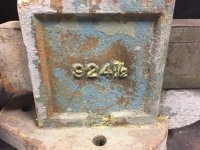
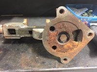
I have an Athol 924-1/2 Vice that has been laying around my shop for some time. It needs some TLC and a set of vice jaws.
I've done some looking, but haven't been able to find anything!
In any event, i'll post up a couple pics. Maybe someone can lead me in the right direction.
Oh yeah, it has a broken bolt in one of the chuck jaw mounts.
Other than that, I think with a little TLC and some jaws, I'll be in business!
Thanks in advance for any help you all can give me.
Mike
 

Attachments

  • IMG_6806.jpg
    IMG_6806.jpg
    140.9 KB · Views: 32
  • IMG_6809.jpg
    IMG_6809.jpg
    139.7 KB · Views: 38
  • IMG_6807.jpg
    IMG_6807.jpg
    149.8 KB · Views: 30
  • IMG_6805.jpg
    IMG_6805.jpg
    143.6 KB · Views: 32

jimreed2160

Well-known member
Joined
Aug 7, 2016
Messages
3,589
Location
Tallahassee FL
A stuck up little Parker

I picked up this old Parker #22 from that famous on line auction site. It is not in good shape but it spoke to me in a pitiful voice. There is no base and the dynamic is frozen.

DSCN1875.jpg


Everything else is in pretty good shape and I really like the anvil horn. I am soaking with Liquid Wrench and tapping with a brass hammer. The LW is getting lost in the cracks and I am taking that as a good sign. I will keep up with the LW, tapping, and reversing for a few weeks. It may need a good soak.
 

GETRIDAONE

Well-known member
Joined
May 21, 2013
Messages
1,549
Location
Auburn, GA
Hi All!
I have an Athol 924-1/2 Vice that has been laying around my shop for some time. It needs some TLC and a set of vice jaws.
I've done some looking, but haven't been able to find anything!
In any event, i'll post up a couple pics. Maybe someone can lead me in the right direction.
Oh yeah, it has a broken bolt in one of the chuck jaw mounts.
Other than that, I think with a little TLC and some jaws, I'll be in business!
Thanks in advance for any help you all can give me.
Mike

http://www.benchvisejaws.com/starrett-vise-jaws/
 

kwhunter

Well-known member
Joined
Oct 9, 2016
Messages
61
Location
@home
The way I did that, (assuming 1/4" dia pins) was to assemble the vise, and tighten the main screw firmly, to tension the parts in place, then drill both sides with a letter 'F' (.257) drill. I'd then remove the nut, and clamp up the end cap firmly to the fixed jaw casting, with a .257 pin on one side for alignment. Then, I'd tap the other side 5/16-18, through both parts. After putting in a set-screw to maintain alignment on that side, I'd tap the other side.

Then, I'd trim the set-screws to length as needed, and turn that area of the setscrews which enter the nut to .255/.253, a slight clearance in the drilled hole in the nut. (a little bit looser wouldn't hurt anything, as the nut can 'float' a little, but shouldn't bind, as it adjusts its location to suit the main screw. If you don't do turning, you can just grind the tips of the set-screws, spinning them neatly against the grinding wheel, til they fit with a slight clearance.

With the smaller vises which use 3/16" pins, one should drill #7, and use a 1/4-20 tap.

As far as I know, this method has been the 'regular' or 'usual' practice for working on these vises for quite a few years.....I first saw it done in the late 1970's.....a finicky mechanic I knew bought himself a new Wilton vise, and thought it too shaky, so he very carefully honed the bore of the fixed jaw, and sent the movable jaw out to a specialist firm to be hard-chromed and ground to a 'perfect sliding fit with no shake'.....and re-ground the jaws to dead smooth and perfect alignment. He was 'particular' about his equipment, to be sure, and was locally well-known for doing good work. I learned from knowing that gentleman, and miss him.

cheers

Carla

Thanks Carla, very neat process plan; I will have some fun with the vise for sure, but won't overdo it.
 

Smoil

New member
Joined
Jan 18, 2017
Messages
4
Re: Advice on removing main nut pin

I'd think you are seeing an 'optical illusion'......there isn't any small pin in the larger pin, but, rather, the protrusion of the 'nib' or 'teat' left when the pin was parted off has the appearance of a smaller central pin.

Just drive the pin out as usual........ : )

cheers

Carla

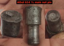
Carla, you were spot on.
 

Attachments

  • athol-614-main-nut-pin.jpg
    athol-614-main-nut-pin.jpg
    42.7 KB · Views: 59
To avoid these ads, REGISTER NOW!
Top Bottom