To avoid these ads, REGISTER NOW!

Hardinge Lathe Accuslide CNC Lathe Control Retrofit

slodat

ALLIANCE MEMBER
Joined
Feb 6, 2010
Messages
3,679
Location
Central-ish, WA
Hardinge Accuslide CNC Lathe Control Retrofit

Some trading with a buddy resulted in this guy coming home the other day..

90aa8e1b98daf0d1ae5f966217ace2a9.jpg

Before we loaded it on the trailer:
16d9625014e746bf3e21221e9aacbbd1.jpg

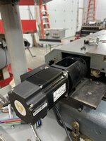
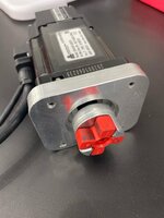
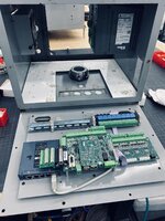
Hardinge lathe with Upgrade Technologies Accuslide CNC conversion with Fagor control. I will be installing new servos and Centroid control. Very similar to my mill conversion. Should make a really nice CNC lathe for my shop.

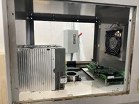
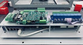
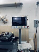
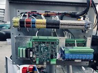
Got the lathe unloaded off the trailer and roughly in its resting place. It will stay on the cribbing until the controls are installed. Overall it’s in excellent condition. Was quite dirty. Still some cleaning left. Starting to sort out the existing control circuits. Most of the new control components are ordered. The existing Accuslide CNC conversion mechanical components look to be in great condition. I’ll have to source or make a few way cover parts that are missing. I have a 3 jaw chuck on the way.

4fe748e11471ea8d2262b9ad38c2a9e3.jpg

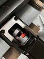
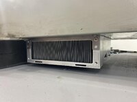
I sorted out how to move the Accuslide away from the spindle. This will allow me full use of the X axis travel.

fa5355dc3a2fa4ef135f1f7dc1fd2f58.jpg

The lathe will be quite similar to my mill build: Centroid Acorn control, DMM AC servos and Hitachi SJ-P1 spindle VFD running closed loop vector control.
 

Attachments

  • fa5355dc3a2fa4ef135f1f7dc1fd2f58.jpg
    fa5355dc3a2fa4ef135f1f7dc1fd2f58.jpg
    171.6 KB · Views: 3
  • 4fe748e11471ea8d2262b9ad38c2a9e3.jpg
    4fe748e11471ea8d2262b9ad38c2a9e3.jpg
    169 KB · Views: 4
  • 16d9625014e746bf3e21221e9aacbbd1.jpg
    16d9625014e746bf3e21221e9aacbbd1.jpg
    239.7 KB · Views: 5
  • 90aa8e1b98daf0d1ae5f966217ace2a9.jpg
    90aa8e1b98daf0d1ae5f966217ace2a9.jpg
    124.7 KB · Views: 3
Last edited:
To avoid these ads, REGISTER NOW!
OP
S

slodat

ALLIANCE MEMBER
Joined
Feb 6, 2010
Messages
3,679
Location
Central-ish, WA
Re: Hardinge Accuslide CNC Lathe Control Retrofit

Parts are starting to arrive. This is the control panel layout. Test piece is made out of 1/8 mdf on the laser to check dimensions, layout, etc. I think this is what I’ll be going with.

608ceceaa72b4adfac7fc57cd2a1a6d6.jpg
 

Attachments

  • 608ceceaa72b4adfac7fc57cd2a1a6d6.jpg
    608ceceaa72b4adfac7fc57cd2a1a6d6.jpg
    180.9 KB · Views: 2

2oolhound

Well-known member
Joined
Dec 18, 2010
Messages
5,918
Location
BC Canada
Show off! :drool::drool:

I know very little about them but I have touched one. I bid on it in auction but was beat by over 10 X my bid. Pretty nice lathe, I'll be following along here.
 
OP
S

slodat

ALLIANCE MEMBER
Joined
Feb 6, 2010
Messages
3,679
Location
Central-ish, WA
Touchscreen arrived. Got a great deal on Amazon Warehouse deals. Almost half price.

MDF mockup looks good.

cde8d95ab27c777d155b89496c1e41c3.jpg

The Hitachi VFD is able to be mounted through the back of the cabinet, placing the cooling fans and heat sink outside. I’ll stand the cabinet off the side of the machine about 3”. Chips shouldn’t be a problem because it’s under the chip tray.

fc6f2b83a9261518dbc51d44cbd47743.jpg

7901713d7b2fd26576f74aff44665175.jpg
 

Attachments

  • fc6f2b83a9261518dbc51d44cbd47743.jpg
    fc6f2b83a9261518dbc51d44cbd47743.jpg
    214.3 KB · Views: 4
  • cde8d95ab27c777d155b89496c1e41c3.jpg
    cde8d95ab27c777d155b89496c1e41c3.jpg
    640.4 KB · Views: 4
  • 7901713d7b2fd26576f74aff44665175.jpg
    7901713d7b2fd26576f74aff44665175.jpg
    151.4 KB · Views: 4
Last edited:

matt_i

Well-known member
Joined
Mar 14, 2008
Messages
10,722
Location
SE Michigan
This looks like another great CNC machine taking shape!

Is this machine already ballscrew-ready without replacing Acme?

That is a clever mounting for the VFD cooling...I have to take a closer look at that...have an old machine I'm working on where that could benefit :)

How do you "tool" it, just a gang of cutters attached to the cross-slide with space between them for actual use? Or are you going to turret-post it...thinking like Dorian's QTCP post or ?
 
OP
S

slodat

ALLIANCE MEMBER
Joined
Feb 6, 2010
Messages
3,679
Location
Central-ish, WA
Re: Hardinge Accuslide CNC Lathe Control Retrofit

It has ball screws already. I’m replacing an existing Fagor CNC control. Tools mount on the gang block. I’m not sure about how that all works yet. I have some learning to do.

DMM AC servos arrived today. I did a lot of measuring prior to ordering. I knew they were close. They are! The original servos had 3/8” shafts. I found a 1/4 coupler of the same style. Worked great with the DMM’s 1/4” shaft. I had to turn down the heads of the socket head cap screws so they would go in to the bracket straight.

The X axis bracket is going to have to have about 0.4” milled off so the coupler will engage. I’m thinking I can modify the existing part. Not sure about extending the existing threaded mounting holes further in.. I may have to make a new bracket.

c9a6bafe86143e82230e88b156ac2710.jpg

Line scratched showing where motor would mount up:
a4267e725c2851d12fe7317873a6f462.jpg

bfb41c97ce89a7ea96562b1778242712.jpg

The Z axis coupler has a much smaller gap. I think it will need to be closed up, too.

20c7e17ffdcc2e975ed8aa987e1c0137.jpg

91111d468db25b2a092b1e0cd606bef2.jpg
 

Attachments

  • bfb41c97ce89a7ea96562b1778242712.jpg
    bfb41c97ce89a7ea96562b1778242712.jpg
    223.8 KB · Views: 5
  • 20c7e17ffdcc2e975ed8aa987e1c0137.jpg
    20c7e17ffdcc2e975ed8aa987e1c0137.jpg
    222.5 KB · Views: 3
  • 91111d468db25b2a092b1e0cd606bef2.jpg
    91111d468db25b2a092b1e0cd606bef2.jpg
    203.8 KB · Views: 2
  • c9a6bafe86143e82230e88b156ac2710.jpg
    c9a6bafe86143e82230e88b156ac2710.jpg
    232.1 KB · Views: 1
  • a4267e725c2851d12fe7317873a6f462.jpg
    a4267e725c2851d12fe7317873a6f462.jpg
    168.1 KB · Views: 1
OP
S

slodat

ALLIANCE MEMBER
Joined
Feb 6, 2010
Messages
3,679
Location
Central-ish, WA
Re: Hardinge Accuslide CNC Lathe Control Retrofit

Got the part modeled.

Original motor mount:
4afe906b8937b98f6dec0c14fc92cda1.jpg

228dfdc3e6bae2ec2ee0500c6df58450.png

All I have on hand is some 3.5” round stock. This is definitely the most complicated (feature rich?) part I’ve made. I’m sure the first will be a test part.

b1f89d2c16530b06ebc7df282ccf3978.jpg

I ordered a 3 x 3.5” x 12” bar from Xometry. Hopefully I’ll only use a 3” chunk of it for the final part and have plenty left for the Z motor mount.

edit: forgot the mounting holes earlier.
c8be7ad5eacf68005390d8f4519ef84e.jpg
 

Attachments

  • c8be7ad5eacf68005390d8f4519ef84e.jpg
    c8be7ad5eacf68005390d8f4519ef84e.jpg
    38.6 KB · Views: 1
  • b1f89d2c16530b06ebc7df282ccf3978.jpg
    b1f89d2c16530b06ebc7df282ccf3978.jpg
    30.9 KB · Views: 1
  • 228dfdc3e6bae2ec2ee0500c6df58450.png
    228dfdc3e6bae2ec2ee0500c6df58450.png
    278.7 KB · Views: 1
  • 4afe906b8937b98f6dec0c14fc92cda1.jpg
    4afe906b8937b98f6dec0c14fc92cda1.jpg
    133.8 KB · Views: 1
OP
S

slodat

ALLIANCE MEMBER
Joined
Feb 6, 2010
Messages
3,679
Location
Central-ish, WA
Re: Hardinge Accuslide CNC Lathe Control Retrofit

Starting to get the components laid out. I’d like to get everything in the existing two enclosures.

Spindle drive and AC components:

8df0e90eb1bb8cc31c18effddb755416.jpg

Control and servo drives in the control panel enclosure:
601d40169a4a91b5ee3c43c8089c6212.jpg

135dd80b29ff0110ddfd7ac539495079.jpg
 

Attachments

  • 601d40169a4a91b5ee3c43c8089c6212.jpg
    601d40169a4a91b5ee3c43c8089c6212.jpg
    198.2 KB · Views: 1
  • 8df0e90eb1bb8cc31c18effddb755416.jpg
    8df0e90eb1bb8cc31c18effddb755416.jpg
    217.2 KB · Views: 1
  • 135dd80b29ff0110ddfd7ac539495079.jpg
    135dd80b29ff0110ddfd7ac539495079.jpg
    202.1 KB · Views: 1

American Locomotive

Well-known member
Joined
Jan 8, 2017
Messages
10,929
Location
Rhode Island
I'd really be weary of the lovejoy-style couplings. Under high loads you'll get lost some lost motion unless your control is using direct positional feedback from linear scales. You could mitigate it somewhat using a very high durometer spider I suppose.

Have you looked into bellows (or even helical) couplings? You can find them pretty inexpensively on Amazon, and they have far more torsional rigidity.

But, for what your trying to do, the lost motion of the jaw coupling's spider may not be an issue.
 
OP
S

slodat

ALLIANCE MEMBER
Joined
Feb 6, 2010
Messages
3,679
Location
Central-ish, WA
Re: Hardinge Accuslide CNC Lathe Control Retrofit

Coupling is what came on the machine. The GS couplings are zero backlash made for the application from what I’ve read on their website.
 

American Locomotive

Well-known member
Joined
Jan 8, 2017
Messages
10,929
Location
Rhode Island
Ah, zero backlash is not the same thing as zero lost motion.

Backlash basically refers to the distance the motor (or handwheel) can physically move when switching direction before the table/tool/slide/whatever responds. Lost motion on the other hand includes things like deflection and flex in components (the "spring windup" I like to call it).

So while the GS coupling may be 0 backlash, it almost certainly has quite a bit of lost motion under load due to the spider.

The machines I used to work on all used bellows or helical couplings, but our tolerances were down in the +/- 0.0003 range usually. Not sure if a standard coupling would be an issue for you. Just something to consider though.
 
OP
S

slodat

ALLIANCE MEMBER
Joined
Feb 6, 2010
Messages
3,679
Location
Central-ish, WA
The original maker of the retrofit had specs in the tenths, so I'm thinking these couplers are fine. If not I'll sort it out when I get to it. I'm not concerned about the couplers at this point. There are a lot of these conversions in production shops making parts.
 
OP
S

slodat

ALLIANCE MEMBER
Joined
Feb 6, 2010
Messages
3,679
Location
Central-ish, WA
Re: Hardinge Accuslide CNC Lathe Control Retrofit

Made each end of the motor mount in 1/2 material to check dimensions. Went well and I caught a few mistake that would have scrapped the bigger material had I not found them.

32b3db5a5144a0a44ba1d08244435c4a.jpg

063578fbb7c2854b79761c422ddfb319.jpg

Other end:
c40787cdc08817b0312c34cfef25d36d.jpg
 

Attachments

  • c40787cdc08817b0312c34cfef25d36d.jpg
    c40787cdc08817b0312c34cfef25d36d.jpg
    89.9 KB · Views: 1
  • 063578fbb7c2854b79761c422ddfb319.jpg
    063578fbb7c2854b79761c422ddfb319.jpg
    78.5 KB · Views: 1
  • 32b3db5a5144a0a44ba1d08244435c4a.jpg
    32b3db5a5144a0a44ba1d08244435c4a.jpg
    91 KB · Views: 1
OP
S

slodat

ALLIANCE MEMBER
Joined
Feb 6, 2010
Messages
3,679
Location
Central-ish, WA
Re: Hardinge Accuslide CNC Lathe Control Retrofit

The first servo motor mount is coming along. What I started with 3x3x3.5:

b327f5042a2cb4354a1d85293ea7aadc.jpg

Close to fitting correctly. Need to shave a couple faces.

ed6ecaeb187e60c7c17b4edf770699d5.jpg
 

Attachments

  • ed6ecaeb187e60c7c17b4edf770699d5.jpg
    ed6ecaeb187e60c7c17b4edf770699d5.jpg
    811.5 KB · Views: 2
  • b327f5042a2cb4354a1d85293ea7aadc.jpg
    b327f5042a2cb4354a1d85293ea7aadc.jpg
    103.5 KB · Views: 3
OP
S

slodat

ALLIANCE MEMBER
Joined
Feb 6, 2010
Messages
3,679
Location
Central-ish, WA
Finally finished a few adjustments on the servo mount. All went together nicely. I’m new to this cnc machining. Overall, quite happy with it. Bonus is, it will do the job! On to the next.

9e176a2e0547837d5562dfbc8d5384c1.jpg

What I started with:
537fce6653259d256d3534be8883915c.jpg


Control electronics starting to come together.

8cc68f951b5b67b1c1b373bed6f4d568.jpg
 

Attachments

  • 537fce6653259d256d3534be8883915c.jpg
    537fce6653259d256d3534be8883915c.jpg
    232.1 KB · Views: 2
  • 9e176a2e0547837d5562dfbc8d5384c1.jpg
    9e176a2e0547837d5562dfbc8d5384c1.jpg
    273.5 KB · Views: 3
  • 8cc68f951b5b67b1c1b373bed6f4d568.jpg
    8cc68f951b5b67b1c1b373bed6f4d568.jpg
    269.7 KB · Views: 3

cnc-me

Well-known member
Joined
Jan 6, 2010
Messages
1,183
Location
MI
Is that the Acorn board? I got a small Lathe that needs one. Right now it's running Zeus, a DOS controller that runs on a PC. Zeus is pretty good, but it's really a mill control made to act like a Lathe control.
 

Firebrick43

Well-known member
Joined
May 12, 2015
Messages
13,989
Location
West central Indiana
Ah, zero backlash is not the same thing as zero lost motion.

Backlash basically refers to the distance the motor (or handwheel) can physically move when switching direction before the table/tool/slide/whatever responds. Lost motion on the other hand includes things like deflection and flex in components (the "spring windup" I like to call it).

So while the GS coupling may be 0 backlash, it almost certainly has quite a bit of lost motion under load due to the spider.

The machines I used to work on all used bellows or helical couplings, but our tolerances were down in the +/- 0.0003 range usually. Not sure if a standard coupling would be an issue for you. Just something to consider though.


I would tend to agree with you on a standard 2 wing lovejoy. It’s not actually the polyurethane spider it’s the shape and material of the coupler. It about 10 times less stiff than an equivalent bellows style coupler.

However the similar(but different geometry) 3 wing European stainless steel curved jaw couplers with the no back lash spiders have the same stiffness as as the bellows type couplers. And in the German Cnc machines I work on use them on the axis servos. Some of the old Burkhard Weber’s made in the early 90’s still used bellows but the new waldrich colburg, stama’s, shaundt’s, and junkers all used the curved jaw couplers.

https://www.wmh-trans.co.uk/image.php?filename=292-003-041.jpg&stockcode=292-003-041&category=0023000300070006&width=1000&height=1000
 
OP
S

slodat

ALLIANCE MEMBER
Joined
Feb 6, 2010
Messages
3,679
Location
Central-ish, WA
Is that the Acorn board? I got a small Lathe that needs one. Right now it's running Zeus, a DOS controller that runs on a PC. Zeus is pretty good, but it's really a mill control made to act like a Lathe control.


Yes, this is Centroid Acorn. I highly recommend it. This is my third machine I’ve used Acorn on. Very happy with it.
 
To avoid these ads, REGISTER NOW!
OP
S

slodat

ALLIANCE MEMBER
Joined
Feb 6, 2010
Messages
3,679
Location
Central-ish, WA
It’s always a challenge fitting and mounting all of the components, especially when using the existing enclosures. Came up with a second tier on the HMI rear door. This is where the original electronics were. Turned out well. Everything is secure and the terminals and I/O status LED’s on the lower board are still accessible and visible. Lower layer is gigabit Ethernet switch and 1616 Ethernet I/O expansion. Upper layer is Acorn control board and 8 output interposing relay board.

b438cdd218c0655bd957bee74a9e777b.jpg

5f51fa9173332e625243a1324b558159.jpg
 

Attachments

  • b438cdd218c0655bd957bee74a9e777b.jpg
    b438cdd218c0655bd957bee74a9e777b.jpg
    218.4 KB · Views: 2
  • 5f51fa9173332e625243a1324b558159.jpg
    5f51fa9173332e625243a1324b558159.jpg
    279.9 KB · Views: 2

manwithtools

ALLIANCE MEMBER
Joined
Aug 24, 2015
Messages
13,657
Location
Lebanon, TN
Nice work! There is a bit of an art to making everything fit in the available area, when it's less than optimal to begin with.
 

American Locomotive

Well-known member
Joined
Jan 8, 2017
Messages
10,929
Location
Rhode Island
I would tend to agree with you on a standard 2 wing lovejoy. It’s not actually the polyurethane spider it’s the shape and material of the coupler. It about 10 times less stiff than an equivalent bellows style coupler.

However the similar(but different geometry) 3 wing European stainless steel curved jaw couplers with the no back lash spiders have the same stiffness as as the bellows type couplers. And in the German Cnc machines I work on use them on the axis servos. Some of the old Burkhard Weber’s made in the early 90’s still used bellows but the new waldrich colburg, stama’s, shaundt’s, and junkers all used the curved jaw couplers.

https://www.wmh-trans.co.uk/image.php?filename=292-003-041.jpg&stockcode=292-003-041&category=0023000300070006&width=1000&height=1000
Interesting! Most of the German machines I used to work on (Index, Traub) and Japanese machines (Tsugami) all used bellows couplings, and these were new machines (2010-2019 Vintage). Some of the Index's had belt-drives to their axis mechanisms, but they compensated by having scales.
 

Firebrick43

Well-known member
Joined
May 12, 2015
Messages
13,989
Location
West central Indiana
Interesting! Most of the German machines I used to work on (Index, Traub) and Japanese machines (Tsugami) all used bellows couplings, and these were new machines (2010-2019 Vintage). Some of the Index's had belt-drives to their axis mechanisms, but they compensated by having scales.

The more brands I have worked on the more I have come to realize how “set in their ways” some machine builders are. Sometime good, sometimes bad, sometimes just odd and different. Bellows couplers used to be universal across Japanese, German, and American but I would say they are more the exception now.

Even your comments about compensating with scales is interesting to me as all the machines I have worked on used scales. And as a result my previous employer ordered a gaggle of 8800 hmc mazaks and a dozen of their intergrex e670h. When a group of us attended the Mazak maintenance training the trainers were completely baffled that are machines had scales and we were baffled why they would ask why as every machine we had came with scales.

Well Mazak direct drives and oil cools their ballscrews so even a machine with a 20’ long ball screw should maintain a 20 micron accuracy over its length.

And shuaundt has hydrostatic screws which are just strange.
 
Last edited:

American Locomotive

Well-known member
Joined
Jan 8, 2017
Messages
10,929
Location
Rhode Island
In our case, the Index multi-spindles didn't use scales, but all the screws were directly connected with bellows couplings.

Their 3-turret lathes on the other hand use a complicated "scissors mechanism" (as they call it) to move the turrets in X and Y. It allows for the machine to be extremely compact compared to just about everything else on the market, but I believe the mechanism sort of inherently requires scales since it relies on a lot of things working together and there's probably a lot of lost motion that can stack up.

In general, I think the scales (depending on where they are mounted) allow you to maintain accuracy easier under high cutting loads, since the machine can basically compensate for its own floppy-ness .
 

cnc-me

Well-known member
Joined
Jan 6, 2010
Messages
1,183
Location
MI
It’s always a challenge fitting and mounting all of the components, especially when using the existing enclosures. Came up with a second tier on the HMI rear door. This is where the original electronics were. Turned out well. Everything is secure and the terminals and I/O status LED’s on the lower board are still accessible and visible. Lower layer is gigabit Ethernet switch and 1616 Ethernet I/O expansion. Upper layer is Acorn control board and 8 output interposing relay board.

b438cdd218c0655bd957bee74a9e777b.jpg

5f51fa9173332e625243a1324b558159.jpg

Know what you mean, seems like you always need more room than you have.
Here's one I did a while back it's for a small AXYZ CNC Router.

View media item 107367
 

Attachments

  • b438cdd218c0655bd957bee74a9e777b.jpg
    b438cdd218c0655bd957bee74a9e777b.jpg
    218.4 KB · Views: 2
  • 5f51fa9173332e625243a1324b558159.jpg
    5f51fa9173332e625243a1324b558159.jpg
    279.9 KB · Views: 2

cnc-me

Well-known member
Joined
Jan 6, 2010
Messages
1,183
Location
MI
This is my third Acorn conversion (5x8' router, mill and now the lathe). I really like it. How's it working out for you?

It's not, I don't have any Acorn powered machines yet, though I have always been a fan of Centroid controls. Back in the late 90's I was converting a 5 x 10
router, and checked into Centroid, but their controls back then cost more than the machine. Went with CNC PRO by Doug Yeager, It's pretty good but has its limits. I would say that it's better than Mach 3 which did not exist back then.
CNC Pro seems to have a problem with running at higher speeds anything north of 85 FPM is going to cause problems. On mills and small routers it's pretty decent, but large routers or faster mills it's not gonna cut it. It's now open source so anyone can modify it.
 
OP
S

slodat

ALLIANCE MEMBER
Joined
Feb 6, 2010
Messages
3,679
Location
Central-ish, WA
Re: Hardinge Accuslide CNC Lathe Control Retrofit

Control panel sitting on the lathe.

e2ed0e9eb253cc0e1481a21208fb8417.jpg

bcfc4e3e6822175d644efdc3796e7ba1.jpg
 

Attachments

  • bcfc4e3e6822175d644efdc3796e7ba1.jpg
    bcfc4e3e6822175d644efdc3796e7ba1.jpg
    188.1 KB · Views: 1
  • e2ed0e9eb253cc0e1481a21208fb8417.jpg
    e2ed0e9eb253cc0e1481a21208fb8417.jpg
    184.5 KB · Views: 2
OP
S

slodat

ALLIANCE MEMBER
Joined
Feb 6, 2010
Messages
3,679
Location
Central-ish, WA
Finally getting to wiring in the new control. It’s a lot in a small space.

3ec918c685a5e4143f15634dfa9f2296.jpg

8f529da55b409ab68e8e907ac27c6141.jpg

0dd3c3ec8c714a28bca98ffd08f0beb3.jpg

6805bbcac294a4d2260f420a9b41d141.jpg
 

Attachments

  • 6805bbcac294a4d2260f420a9b41d141.jpg
    6805bbcac294a4d2260f420a9b41d141.jpg
    362.8 KB · Views: 2
  • 0dd3c3ec8c714a28bca98ffd08f0beb3.jpg
    0dd3c3ec8c714a28bca98ffd08f0beb3.jpg
    329 KB · Views: 3
  • 3ec918c685a5e4143f15634dfa9f2296.jpg
    3ec918c685a5e4143f15634dfa9f2296.jpg
    321.5 KB · Views: 2
  • 8f529da55b409ab68e8e907ac27c6141.jpg
    8f529da55b409ab68e8e907ac27c6141.jpg
    282.8 KB · Views: 3
OP
S

slodat

ALLIANCE MEMBER
Joined
Feb 6, 2010
Messages
3,679
Location
Central-ish, WA
I've been chipping away at the CNC lathe project the last few evenings. It's close to being ready to power up and start checking things out. Plenty of little details to get dialed in yet. Once it's powered up, it goes pretty quickly on the remaining little stuff. The control board, i/o expansion, ethernet switch and a row of terminal strips are on the control panel rear door. The upper enclosure holds the servo drives, control computer, and front panel.

A467B537-8568-4521-AAAA-994890EA81EA.jpeg

The lower enclosure houses the AC power conditioning and distribution, spindle VFD, DC power supplies, and a few relays.
35DC86FA-4290-4453-BEF0-6CD3970F6456.jpeg

It will be nice getting this machine up and running. I have a couple parts I want to run on it.
 

RickP

Well-known member
Joined
Jan 15, 2013
Messages
1,547
Location
Annapolis, MD
That looks like a LOT of electrical components -- good thing you did this kind of thing once or twice in your day job!

It really is amazing that old iron like your lathe can be brought into the 21st century, and made useful again for your type of manufacturing.
 
OP
S

slodat

ALLIANCE MEMBER
Joined
Feb 6, 2010
Messages
3,679
Location
Central-ish, WA
Almost done with wiring on the lathe. Waiting on some stuff to arrive to finish the encoder wiring and I'll be done.

Lower cabinet:
8E8EA14F-4EE0-4C1E-A7CE-F58C88EBA68C.jpeg

There are a few spots that could use a blanking plate. 3d printed this one. Worked out well.
C7807B61-8909-425D-8BE0-7FD6AE9F5BDC.jpeg

It looks like originally there was a cover for the axis ball screw. It's long gone.
B07F857D-A700-421A-8D6F-A4A2F5134116.jpeg

Cut this out of 12ga mild steel. It's way over kill, but the sheet was on the plasma. Worked well.
563D34AC-7F07-4A8F-9C62-6A23DA9C389E.jpeg

Close to be wrapped up.

9CEF0CF1-467E-4D01-BFD1-EB2FD03C72A4.jpeg

I have a lot of learning to do before I'll be doing anything meaningful with the lathe. I ordered a few tools. I have a lot of tool holders I bought a while back. Need to get a small assortment of tools and sort out using the conversational programming to make a part. The encoder will allow for threading.
 
To avoid these ads, REGISTER NOW!
Top Bottom