To avoid these ads, REGISTER NOW!

Above 1200 Sq/FT The ASYLUM - Happy 40th Birthday to Me! (Est. 2005)

Wokspaces above 1200 squarefeet.
To avoid these ads, REGISTER NOW!

andyvh1959

Well-known member
Joined
Feb 15, 2020
Messages
2,590
Location
Green Bay WI
Thanks for the compassion about my divorce, but it was a real blessing really. Had I had any cojones back in 2002 it never would have happened. And for that I am finally done kicking my ***. My wife, now of two years, and friend of ten years already has me far happier after ten years than the previous one at one year. Match.com came through. Just a shame I didn't meet her 20 years ago. Of course, back then we'd both be cheating on our others.

Back in 04 I had 1st dibs on two garages, for free, all I had to do was break them down and move them out, similar to what I did for my build back in 98. Wife at the time nixed the idea, claiming I'd "waste more money making those garages look decent for our house, and where would you put the wall sections anyway?" We had a large lot on which it'd been easy to stack and tarp the wall sections. I caved and watched the garages turned into a couple huge dumpster loads.

Current, right wife, had no issues with me building a garage now, on the same property I was in back in 04. I said I'd only be building it with cash, no financing. She said go for it. When the right one comes along, its all good.
 

cbacres

Well-known member
Joined
May 28, 2010
Messages
5,998
Location
SW Florida
Mark, you’re kicking **** in your shop.
Sorry I haven't stopped by, just been peeking in the windows .

The Quick change is the way to go, I was lucky as the first lathe came with a set.

How do you like the Keyless?

Craig
 
OP
S

shopnut

Well-known member
Joined
Feb 22, 2006
Messages
4,237
Location
Florida
Thanks for the compassion about my divorce, but it was a real blessing really. Had I had any cojones back in 2002 it never would have happened. And for that I am finally done kicking my ***. My wife, now of two years, and friend of ten years already has me far happier after ten years than the previous one at one year. Match.com came through. Just a shame I didn't meet her 20 years ago. Of course, back then we'd both be cheating on our others.

Back in 04 I had 1st dibs on two garages, for free, all I had to do was break them down and move them out, similar to what I did for my build back in 98. Wife at the time nixed the idea, claiming I'd "waste more money making those garages look decent for our house, and where would you put the wall sections anyway?" We had a large lot on which it'd been easy to stack and tarp the wall sections. I caved and watched the garages turned into a couple huge dumpster loads.

Current, right wife, had no issues with me building a garage now, on the same property I was in back in 04. I said I'd only be building it with cash, no financing. She said go for it. When the right one comes along, its all good.
I guess it's like they say... "All's well that ends well" (with your wife #2). It definitely pays to find someone that "gets you". I think my wife scratches her head a lot trying to figure out what I'm up to half the time.
 
OP
S

shopnut

Well-known member
Joined
Feb 22, 2006
Messages
4,237
Location
Florida
Mark, you’re kicking **** in your shop.
Sorry I haven't stopped by, just been peeking in the windows .

The Quick change is the way to go, I was lucky as the first lathe came with a set.

How do you like the Keyless?

Craig
You know, I've had that feeling someone was watching me for a couple weeks now. Now I know why! LOL

I'm making some good headway lately and it feels really good. I got a lot cooking too that I'll be sharing shortly as things develop.

Lucky you on the QCTP. What a time saver!

The keyless drill chuck is worth the money. I had one on my big drill press for years and loved it. If I would have searched around some, I probably could have found an adapter to reuse the old keyless chuck on the new Delta press. But I'm okay having the second keyless waiting in the drawer should I ever need to convert the big press back from milling to drilling fast.
 
OP
S

shopnut

Well-known member
Joined
Feb 22, 2006
Messages
4,237
Location
Florida
TIME FOR A NEW DIGITAL TV ANTENNA…

Back in 2011, I moved the old antenna down out of the way for the front loft project and it was temporarily mounted there for 9 years. Being lower, it was more susceptible to having Spanish moss land on it from nearby trees. And the reception was lousy. I finally found the time to return it to the proper spot for capturing those free TV signals.

attachment.php


After receiving the first antenna, I thought it as a pretty good value for the price, so I ordered a second one as a replacement to store away. The one that had been in use was ready for the trash bin, so I pulled the new one out of storage.

attachment.php


I’m getting a little fancier with how I’m mounting it this time. Rather that just mounting it directly, I’m adding a hinge to make it a bit easier to install, and later, service if needed. This allowed me to do all the work with it hanging straight down within easy reach from the manlift parked on stable concrete.

attachment.php


attachment.php


attachment.php


And here it is, all back up and ready to transmit signals. I trimmed down a scrap of siding tin to just a single rib with flanges to become a stiffener and also a wireway for the cable.

attachment.php


Mission accomplished… I went from 3 channels to 29 so I am pretty happy.

attachment.php


I noticed after it was up that the mount board has a slight bow to it. If you look back at the 4th picture with it hanging straight down, you will also notice the bow. So I guess I messed up… I should have made sure the board was straight before adding the stiffening rib. Oh well, it works well again and doesn’t look too hideous.
 

Attachments

  • 4298-TV-Antenna-16.jpg
    4298-TV-Antenna-16.jpg
    115.3 KB · Views: 417
  • 4297-TV-Antenna-14.jpg
    4297-TV-Antenna-14.jpg
    93.1 KB · Views: 422
  • 4296-TV-Antenna-08.jpg
    4296-TV-Antenna-08.jpg
    55.1 KB · Views: 413
  • 4295-TV-Antenna-07.jpg
    4295-TV-Antenna-07.jpg
    102.9 KB · Views: 422
  • 4294-TV-Antenna-06.jpg
    4294-TV-Antenna-06.jpg
    105.3 KB · Views: 422
  • 4293-TV-Antenna-04.jpg
    4293-TV-Antenna-04.jpg
    162.7 KB · Views: 418
  • 4292-TV-Antenna-02.jpg
    4292-TV-Antenna-02.jpg
    58.5 KB · Views: 418
Last edited:
OP
S

shopnut

Well-known member
Joined
Feb 22, 2006
Messages
4,237
Location
Florida
Re: The ASYLUM - Turning a Crazy Vision into a Lakefront Gearhead Getaway: Year 6

Shopnut
Hoping you and yours have a great Thanksgiving

Sent from my SM-A102U using The Garage Journal mobile app
Same to you and yours Harley Jim!

It's going to be a small get-together this year, but we will have a good time and there will be plenty of good food. Plus the kids are pretty savvy with that facetime stuff.
 
OP
S

shopnut

Well-known member
Joined
Feb 22, 2006
Messages
4,237
Location
Florida
A LITTLE MORE WORK ON THE OLD GAS PUMP…

It didn’t take me long to find a suitable light fixture for inside the gas pump. I also had the computer cleaned up, oiled, and working properly again, so it was time to tear it apart.

Here is the LED light I found for it.

attachment.php


I mounted it at an angle to light up the “Mobil” logo and shine down on the pump face.

attachment.php


I had to make a couple of custom brackets to do so.

attachment.php


Here is the computer ready to go back in. The numbers on the side that will be facing out cleaned up well enough that no repainting was necessary.

attachment.php


While it was apart again, I decided to check if one of my 110v motors could fit in there to drive the meter when I wanted to show people how it works. The good news is there is just enough space to squeeze it in there. Someday, when I run out of things to do, I will come up with a pulley/chain drive system to go from the motor shaft to the computer input (arrows pointing to them)

attachment.php


Its ready to put the faceplates back on.

attachment.php


The new LED light is borderline too bright, but it does a nice job of illuminating the whole inside area.

attachment.php
 

Attachments

  • 4305-Gas Pump - Wayne Model 734 - Restoration-73 (LED Light).jpg
    4305-Gas Pump - Wayne Model 734 - Restoration-73 (LED Light).jpg
    54.2 KB · Views: 374
  • 4304-Gas Pump - Wayne Model 734 - Restoration-71 (LED Light).jpg
    4304-Gas Pump - Wayne Model 734 - Restoration-71 (LED Light).jpg
    151.8 KB · Views: 384
  • 4303-Gas Pump - Wayne Model 734 - Restoration-70 (Motor drive).jpg
    4303-Gas Pump - Wayne Model 734 - Restoration-70 (Motor drive).jpg
    138.7 KB · Views: 379
  • 4302-Gas Pump - Wayne Model 734 - Restoration-68 (Computer).jpg
    4302-Gas Pump - Wayne Model 734 - Restoration-68 (Computer).jpg
    78.2 KB · Views: 381
  • 4301-Gas Pump - Wayne Model 734 - Restoration-67 (LED Light).jpg
    4301-Gas Pump - Wayne Model 734 - Restoration-67 (LED Light).jpg
    80.3 KB · Views: 380
  • 4300-Gas Pump - Wayne Model 734 - Restoration-66 (LED Light).jpg
    4300-Gas Pump - Wayne Model 734 - Restoration-66 (LED Light).jpg
    134.1 KB · Views: 375
  • 4299-Gas Pump - Wayne Model 734 - Restoration-64 (LED Light).jpg
    4299-Gas Pump - Wayne Model 734 - Restoration-64 (LED Light).jpg
    148.5 KB · Views: 377
Last edited:

shortykorte

Well-known member
Joined
Sep 1, 2014
Messages
8,038
Location
Tallahassee, Fl
Re: The ASYLUM - Turning a Crazy Vision into a Lakefront Gearhead Getaway: Year 6

Happy Thanksgiving Mark and Family!


Sent from my iPhone using Garage Journal
 
OP
S

shopnut

Well-known member
Joined
Feb 22, 2006
Messages
4,237
Location
Florida
Re: The ASYLUM - Turning a Crazy Vision into a Lakefront Gearhead Getaway: Year 6

Happy Thanksgiving Mark and Family!


Sent from my iPhone using Garage Journal
Thanks Shorty. I hope you had some great food and some memorable times yesterday. And I wish you a wonderful upcoming holiday season.
 
OP
S

shopnut

Well-known member
Joined
Feb 22, 2006
Messages
4,237
Location
Florida
THE OLD SAILBOAT GETS SOME NEW BOTTOM PAINT…

Our weather is finally drying up some right before Thanksgiving and I was able to get back on the boat project in an effort to sell it. The trailer is done (with the exception of tossing on the wheels/tires I bought months ago), the motor is running great again, so it’s down to finishing up the boat itself. I have a number of things I want to do to it yet, but the biggest chore was covering up the hideous bottom of the boat.

Keep in mind, this special “bottom paint” is designed to erode away to keep barnacles and slime from building up on the boat while in water. Well, most of it was gone after all these years and it was time to give this girl a makeover. The problem is, the bunks which the boat rests on make part of the bottom inaccessible while on the trailer. So I devised a way to lift the hull off one bunk at a time. It’s just a simple wooden structure combined with my motorcycle jack

attachment.php


attachment.php


It lifts it just enough to get some sandpaper in there for prep and brush to glide on some new paint. Of course, one side can only be done at a time, but luckily its fast drying paint. In fact, the instructions say and can be put back in water 6 hours after application.

attachment.php


I used a twisted 2x6 and a bowed piece of plywood to my advantage, matching the curvature of the boat. It ended up fitting nicely it the groove at the edge of the boat.

attachment.php


It goes on pretty thin, so after 2 coats, it was still looking blotchy.

attachment.php


After 3 coats it looked pretty uniform and I probably could have called it quits, but I had paint and time available, so a 4th coat went on. I still have a bit of the gallon left over to give the new owner as touchup paint.

Here are the results of my day of work.

attachment.php


attachment.php


I still need to jack up each side and paint the areas under the bunks, but that will be another day. Actually it will probably be a day per side because I will jack it up on one side and apply 4 coats and then let it dry the rest of the day before setting it down on the bunk again.

Big tasks remaining after the bottom paint are buffing the upper white paint to a nice shine, checking the sails out, and wiping down the interior real well. I also need to check if the galley sink is still working and I need to figure out how to flush out any old water/contaminates that might still be in there.
 

Attachments

  • 4312-Hunter-H240-Sailboat-098 (Bottom Paint).jpg
    4312-Hunter-H240-Sailboat-098 (Bottom Paint).jpg
    151.7 KB · Views: 345
  • 4311-Hunter-H240-Sailboat-101 (Bottom Paint).jpg
    4311-Hunter-H240-Sailboat-101 (Bottom Paint).jpg
    156.3 KB · Views: 344
  • 4310-Hunter-H240-Sailboat-091 (Bottom Paint).jpg
    4310-Hunter-H240-Sailboat-091 (Bottom Paint).jpg
    155.9 KB · Views: 344
  • 4309-Hunter-H240-Sailboat-100 (Bottom Paint).jpg
    4309-Hunter-H240-Sailboat-100 (Bottom Paint).jpg
    54.3 KB · Views: 342
  • 4308-Hunter-H240-Sailboat-083 (Bottom Paint).jpg
    4308-Hunter-H240-Sailboat-083 (Bottom Paint).jpg
    156 KB · Views: 339
  • 4307-Hunter-H240-Sailboat-080 (Bottom Paint).jpg
    4307-Hunter-H240-Sailboat-080 (Bottom Paint).jpg
    155.6 KB · Views: 339
  • 4306-Hunter-H240-Sailboat-082 (Bottom Paint).jpg
    4306-Hunter-H240-Sailboat-082 (Bottom Paint).jpg
    153.6 KB · Views: 344
Last edited:

ODIS

Well-known member
Joined
Apr 30, 2012
Messages
2,110
Location
Pacific Northwest
Always amazed at the depth you take all of your projects to. You are, in fact, inspirational!

Trust you and family had a wonderful TG weekend..

Our best to you.
 

shortykorte

Well-known member
Joined
Sep 1, 2014
Messages
8,038
Location
Tallahassee, Fl
Re: The ASYLUM - Turning a Crazy Vision into a Lakefront Gearhead Getaway: Year 6

Wow, a lot different boat than when Craig and I was there. She’s looking quite the treat. Hopefully when you listed it, it’s is a quick sail. Lol.

I’m glad to see another graduate of motorcycle jack engineering. Luckily your project doesn’t fall over.


Sent from my iPhone using Garage Journal
 
OP
S

shopnut

Well-known member
Joined
Feb 22, 2006
Messages
4,237
Location
Florida
ODIS - Thank you! Honestly, it’s the only way I know how to do things and its sometimes a detriment to making fast progress. I hope a few get inspired, because the rest are probably getting bored with all of my details. LOL.

Yes, we had a nice Thanksgiving. Had some great food on TG day and then headed to the beach for a couple days for some R&R. It was easy to keep our distance from the masses.

attachment.php


This 8” crab posed nicely for us.

attachment.php


We had absolutely perfect days… and nights!!

attachment.php


Just a few steps to the beach!

attachment.php


Saw these at an antique store and was tempted… until I saw the $300 price tag on each. Moving right along!

attachment.php


shortekorte - Yeah, hopefully the next time you guys stop by, there will just be a bare patch of grass to look at!

I think that jack has only been used to lift a motorcycle once. LOL. It comes in handy for a ton of other things though.
 

Attachments

  • 4317--Sarasota-Lido-Beach-Trip-01.jpg
    4317--Sarasota-Lido-Beach-Trip-01.jpg
    155 KB · Views: 283
  • 4316-Sarasota-Lido-Beach-Trip-35.jpg
    4316-Sarasota-Lido-Beach-Trip-35.jpg
    127.8 KB · Views: 282
  • 4315-Sarasota-Lido-Beach-Trip-16.jpg
    4315-Sarasota-Lido-Beach-Trip-16.jpg
    138.9 KB · Views: 288
  • 4314-Sarasota-Lido-Beach-Trip-13.jpg
    4314-Sarasota-Lido-Beach-Trip-13.jpg
    157.4 KB · Views: 287
  • 4313-Sarasota-Lido-Beach-Trip-02.jpg
    4313-Sarasota-Lido-Beach-Trip-02.jpg
    146.7 KB · Views: 287
OP
S

shopnut

Well-known member
Joined
Feb 22, 2006
Messages
4,237
Location
Florida
ELECTRONIC PARTS SALES…

Some of you may remember this, but if you want to read the back story, this link will fill you in on the history of how I lucked into acquiring these 1000’s of parts.

Reply #3729 “I’M FINALLY SELLING THOSE ELECTRONIC PARTS”

I’m happy to say with another sale right before Thanksgiving, both stacks of cabinets ($1400 worth) have now been completely paid for with my efforts. Free cabinets! Ongoing future sales should reimburse the $300 shipping charge soon too, I hope.

attachment.php


attachment.php


It has been interesting meeting some nice people who have a passion in the electronics field and enjoy restoring this old equipment. Most buyers are very grateful I’m taking time to offer these parts up because it’s getting harder and harder to find NOS repair parts for this test equipment. The big sources are drying up, apparently.

I’ll keep doing it for a while yet, but I would like to find someone that would be interested in taking the remaining lot off my hands and continue offering them to the enthusiast out there.
 
Last edited:

shortykorte

Well-known member
Joined
Sep 1, 2014
Messages
8,038
Location
Tallahassee, Fl
Re: The ASYLUM - Turning a Crazy Vision into a Lakefront Gearhead Getaway: Year 6

How does one get the list or website? I have a friend that does electronics.


Sent from my iPhone using Garage Journal
 
OP
S

shopnut

Well-known member
Joined
Feb 22, 2006
Messages
4,237
Location
Florida
Re: The ASYLUM - Turning a Crazy Vision into a Lakefront Gearhead Getaway: Year 6

How does one get the list or website? I have a friend that does electronics.


Sent from my iPhone using Garage Journal
Here is the link to what I have available:

http://www.eevblog.com/forum/buysel...-repair-parts-hp-agilent-tektronix-fluke-etc/

Thanks for passing it on. If they see anything they need, just have them text me and I'll give them a quote on parts and shipping. Its pretty painless and I get the parts shipped out fast.

Wintertime seems to be a busier time as I suspect people up north are tinkering on stuff inside with the cold temps outside.
 
To avoid these ads, REGISTER NOW!
OP
S

shopnut

Well-known member
Joined
Feb 22, 2006
Messages
4,237
Location
Florida
REPLACING THE T12 LIGHT FIXTURES IN THE NORTH SIDE BAY…

This project is mostly spurred by my OCD, I suppose. Originally when I starting installing light fixtures in the ASYLUM, I found a decent deal on the old T12 fluorescent troffers, so I bought enough of them (8X) to do the first area… the north side bay. I installed “daylight” bulbs in them and was pretty happy with the lighting in there. Not long later, I stumbled upon a deal where a guy was unloading a pallet full (43X) of T8 troffers and scooped them up to finish the lighting needs in t eh rest of the ASYLUM.

This is where the OCD part comes in. Since I had a surplus of fixtures, I also planned to replace the previously installed T12 fixtures so that the entire shop was lit by the same T8 fixtures. Two of them were already replaced 4 or 5 years ago, but the day had finally come to replace the remaining six.

Here is where I’ve been storing my fixtures until needed… in one of the side lofts. They are in the brown boxes.

attachment.php


I started with the easiest to reach fixtures above the lathe and drill press. The machinery needed to be moved, but with everything on casters, that’s a pretty easy job. A path was cleared to roll in the manlift and here are the results.

attachment.php


I started with the easiest ones because I wanted to establish a routine so the other four in more obscure spots would go smoothly. The second pair to be replaced required a step ladder. At this point, knowing the procedure meant less trips up and down the ladder. Note the Corvette was protected in the “drop zone”

attachment.php


The last pair were the highest and also over the Corvette. Luckily, I could revert back to using the manlift for these.

attachment.php


attachment.php


attachment.php


And finally, all fixtures in the ASYLUM are the same model! This picture shows the 8 in the side bay, as well as a number of them above the yellow library ladder rail.

attachment.php
 

Attachments

  • 4324-Side-Bay-Lights-08.jpg
    4324-Side-Bay-Lights-08.jpg
    151.4 KB · Views: 440
  • 4323-Side-Bay-Lights-06.jpg
    4323-Side-Bay-Lights-06.jpg
    94.2 KB · Views: 445
  • 4322-Side-Bay-Lights-07.jpg
    4322-Side-Bay-Lights-07.jpg
    79.3 KB · Views: 437
  • 4321-Side-Bay-Lights-04.jpg
    4321-Side-Bay-Lights-04.jpg
    107.3 KB · Views: 434
  • 4320-Side-Bay-Lights-03.jpg
    4320-Side-Bay-Lights-03.jpg
    74.8 KB · Views: 440
  • 4319-Side-Bay-Lights-02.jpg
    4319-Side-Bay-Lights-02.jpg
    85.9 KB · Views: 433
  • 4318-Side-Bay-Lights-10.jpg
    4318-Side-Bay-Lights-10.jpg
    134.2 KB · Views: 446
Last edited:

Bob Heine

ALLIANCE MEMBER
Joined
Oct 24, 2009
Messages
10,705
Location
Boca Raton, Florida
Mark, when two T8 fluorescent bulbs burn out, do you plan to shuffle bulbs and convert the troffer to ballastless LED lighting? Not that anyone in their right mind would do that, just asking for a friend.
 

shortykorte

Well-known member
Joined
Sep 1, 2014
Messages
8,038
Location
Tallahassee, Fl
Re: The ASYLUM - Turning a Crazy Vision into a Lakefront Gearhead Getaway: Year 6

The Bob Bulb Shuffle? Ummm????


Looking good Mark. Glad you got the oil leak fixed on the man lift


Sent from my iPhone using Garage Journal
 
OP
S

shopnut

Well-known member
Joined
Feb 22, 2006
Messages
4,237
Location
Florida
Mark, when two T8 fluorescent bulbs burn out, do you plan to shuffle bulbs and convert the troffer to ballastless LED lighting? Not that anyone in their right mind would do that, just asking for a friend.
Actually, I was planning to just leave the T12 troffers up there and go directly to LED bulbs, cutting out the magnetic ballasts. I found a large quantity pack for about 100 bucks. Then my frugal (and OCD) side kicked in and decided to just use the electronic ballast T8 troffers I had in storage to save money and make the entire place the same. Part of that decision was based on the fact that I thought I had plenty of T8 bulbs on hand to fill them too. I did not, and came up three bulbs short. So I had to buy more of the T8 daylight bulbs in the end anyway. Its a much better deal to buy the 12-pack for $37, so now I have 9 bulbs left to either install in new fixtures (maybe down in the garden shed) or use to replace failed bulbs in the ASYLUM.

I have yet to replace a single T8 bulb in any of these fixtures so the 9 spares might last a long time. I might also note that these T8 fixtures are wired to light one bulb even if the other is blown, so that's a handy feature.

I will not be buying any more fluorescent bulbs after this and the next bunch I purchase will be LED conversion bulbs to slowly upgrade this place.

In the end, all fixtures are the same now, I still only spent about 1/3 of what I was originally planning to spend, and all lights come on instantly when I flick the switch (the mag-ballast T12 had delays and sometimes didn't light at all), so I am happy with the decision.
 
Last edited:
OP
S

shopnut

Well-known member
Joined
Feb 22, 2006
Messages
4,237
Location
Florida
Re: The ASYLUM - Turning a Crazy Vision into a Lakefront Gearhead Getaway: Year 6

The Bob Bulb Shuffle? Ummm????


Looking good Mark. Glad you got the oil leak fixed on the man lift


Sent from my iPhone using Garage Journal
Thanks!

Haha, I have the fake oil leak gag sitting out where I can see it and it makes me laugh every time I glance at it.
 
OP
S

shopnut

Well-known member
Joined
Feb 22, 2006
Messages
4,237
Location
Florida
“THIS IS MY BENDPAK” – MAKING THIS LIFT MINE (Part 5 of ?)…

(Note: This is a continuation of a series of entries I made on the custom accessories I was building for my BendPak HD-9XW car lift way back in early 2014.

Here is Part 1 of the series if you care to see the history:
“THIS IS MY BENDPAK” – MAKING THIS LIFT MINE (Part 1 of ?)…

attachment.php


Well, I’m finally getting back to one of the accessories.

A POOR MAN’S SLIDING/ROLLING BRIDGE JACK

When I bought the lift, I just couldn’t justify the extra $1000 for the RJ-45 rolling jack. (Maybe someday when I’m into full restoration of my cars, but not now.) You BendPak guys are familiar with the RJ-45, but for the others, this is what it looks like.

attachment.php


But, I knew I needed something to start with and sprung for the jack plates. I could just buy some bottle jacks and use the BendPak JP-3 or JP-6 as is, but what would be the fun in that? Here is what BendPak intended.

attachment.php


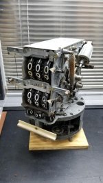
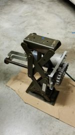
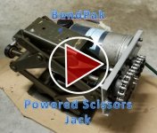
I wanted a more permanent solution and one that I could potentially power up. So I’m in the process of building a poor man’s sliding jack for the HD-9XW. I’m starting with my existing JP-6 plate (which could be fabbed from scratch for a fraction of the cost, btw):

attachment.php


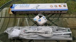
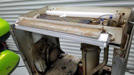
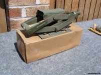
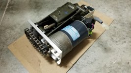
Two of these special military scissor jacks will be mounted on it. Each are rated at 1-1/2 tons and they are pretty compact, yet seem pretty sturdy.

attachment.php


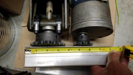
What I like about these particular jacks is the way they were designed to travel up. There is a slight offset that occurs as they rise. On my particular jacks, the top pad moves about 5/8” as it travels from bottom to top. This allows the jack to be very stable while allowing the car to arc as it lifts. The blue pointers indicate the center of the top pads and the offset is witnessed by the distance from the square to the top blue mark.

attachment.php


This crude sketch explains the movement that takes place when a car is lifted on one end (or side). In this exaggerated example, the red arc represents the travel of the rear axle as it is lifted with the front wheel chocked. I feel it’s a good idea that a jack accounts for this movement somehow to avoid extra lateral stresses being induced in the jack arms.

attachment.php


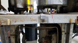
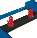
On top of those jack pads, this beam (sold as a floor jack cross beam adapter) will be mounted to make it adjustable in width and also to tie them together for extra lateral stability:

attachment.php


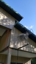
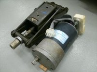
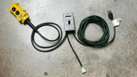
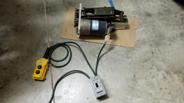
Eventually, I want to take it one step further and power it with some of these reversible 110VAC gearmotors I have lying around. They worked perfectly on the garage door openers and power TV system, and I think they will do great here.

attachment.php


attachment.php
 

Attachments

  • 4331-Floor Jack Cross Beam Example-01.JPG
    4331-Floor Jack Cross Beam Example-01.JPG
    30.9 KB · Views: 422
  • 4330-Jacking-Motion-01.jpg
    4330-Jacking-Motion-01.jpg
    35.2 KB · Views: 417
  • 4329-BendPak-Jack-38.jpg
    4329-BendPak-Jack-38.jpg
    31.3 KB · Views: 419
  • 4328-Military-Scissor-Jack-02.jpg
    4328-Military-Scissor-Jack-02.jpg
    118.9 KB · Views: 422
  • 4327-BendPak JP-6.jpg
    4327-BendPak JP-6.jpg
    11 KB · Views: 411
  • 4326-Bendpak JP-3.JPG
    4326-Bendpak JP-3.JPG
    19.5 KB · Views: 418
  • 4325-BendPak RJ-45 Example.JPG
    4325-BendPak RJ-45 Example.JPG
    35.3 KB · Views: 423
Last edited:
OP
S

shopnut

Well-known member
Joined
Feb 22, 2006
Messages
4,237
Location
Florida
“THIS IS MY BENDPAK” – MAKING THIS LIFT MINE (Part 6 of ?)…

A POOR MAN’S SLIDING/ROLLING BRIDGE JACK (Continued)


I have this cool control pendant that I would like to use somehow, but it has a circuit board on it that may make integration a bit more difficult. We shall see if I can crack the code. I’m kind of thinking it might be more trouble than its worth, but it would be cool.

attachment.php


I purchased the jack cross adapter and here is a rough mock-up under the old rusty Chevelle.

attachment.php


Here is one of the bed motors sitting next to jack.

attachment.php


It was evident during the mock-up stage that the original red cross tube was not wide enough, so I purchased a new one that the black extension arms could slide into. This picture shows the longer tube set on top of the military jacks.

attachment.php


Here is a close-up of the tube resting on the jack. I also purchased some sprockets to give me a speed reduction and torque increase from the gearmotor.

attachment.php
 

Attachments

  • 4336-BendPak-Jack-51.jpg
    4336-BendPak-Jack-51.jpg
    79.5 KB · Views: 431
  • 4335-BendPak-Jack-50.jpg
    4335-BendPak-Jack-50.jpg
    80.9 KB · Views: 425
  • 4334-BendPak-Jack-47.jpg
    4334-BendPak-Jack-47.jpg
    35 KB · Views: 425
  • 4333-BendPak-Jack-46.jpg
    4333-BendPak-Jack-46.jpg
    46.8 KB · Views: 719
  • 4332-BendPak-Jack-28.jpg
    4332-BendPak-Jack-28.jpg
    35.4 KB · Views: 420
Last edited:
OP
S

shopnut

Well-known member
Joined
Feb 22, 2006
Messages
4,237
Location
Florida
“THIS IS MY BENDPAK” – MAKING THIS LIFT MINE (Part 7 of ?)…

A POOR MAN’S SLIDING/ROLLING BRIDGE JACK (Continued)


I got a little further with the jack/motor assembly. The first step was creating a base plate that would tie the motor and jack together. The end cap of the gearmotor has a flat surface with 4 mounting bolts that will work nicely. But the jack attachment needs to stay aligned with the main lift screw. So my plan was to use some “shaft collars” to clamp onto the 1” diameter cross rod that the main screw bears on. Some spacers and longer cap screws were added to provide four mounting points for the new aluminum base plate.

attachment.php


Because I couldn’t find a suitable 4” wide plate in my scrap bin, I used two 2” wide channels to make it. More work, yes, but results were satisfactory. Also shown here is an extension bracket off the rear end of the motor that hangs on the other end of the lift screw, offering support for the cantilevered gearmotor. Another shaft collar is used in conjunction with a bronze flange bushing to provide the bearing for the rotating lift screw. Sprockets were mounted and #41 chain was cut to length to complete the drive system.

attachment.php


attachment.php


attachment.php


In preparation for a quick test, I cobbled up this simple UP/DOWN control pendant for the motor from an old extension cord and a cheap switch purchased on Amazon. The little single gang gray box is what I had on hand to use as a junction box.

attachment.php
 

Attachments

  • 4341-BendPak-Jack-076 (Power Cord).jpg
    4341-BendPak-Jack-076 (Power Cord).jpg
    148 KB · Views: 381
  • 4340-BendPak-Jack-082.jpg
    4340-BendPak-Jack-082.jpg
    132.8 KB · Views: 376
  • 4339-BendPak-Jack-081.jpg
    4339-BendPak-Jack-081.jpg
    98.4 KB · Views: 377
  • 4338-BendPak-Jack-080.jpg
    4338-BendPak-Jack-080.jpg
    142 KB · Views: 379
  • 4337-BendPak-Jack-078.jpg
    4337-BendPak-Jack-078.jpg
    133.3 KB · Views: 378
Last edited:

shortykorte

Well-known member
Joined
Sep 1, 2014
Messages
8,038
Location
Tallahassee, Fl
I’m liking where this is going.

A friend is trying to build an electric fat tire tricycle. Original design had big gear cantilevered from stanchions but due to torque, ended up with gear between stanchions. Also the mounting plate flexed. Just sharing because scissor jack may need rear support which I see you tied together. 9946f31fc752f25fdd59aa6f26a23979.jpg


Sent from my iPhone using Garage Journal
 

Attachments

  • 9946f31fc752f25fdd59aa6f26a23979.jpg
    9946f31fc752f25fdd59aa6f26a23979.jpg
    49.7 KB · Views: 2
OP
S

shopnut

Well-known member
Joined
Feb 22, 2006
Messages
4,237
Location
Florida
I’m liking where this is going.

A friend is trying to build an electric fat tire tricycle. Original design had big gear cantilevered from stanchions but due to torque, ended up with gear between stanchions. Also the mounting plate flexed. Just sharing because scissor jack may need rear support which I see you tied together.
Sent from my iPhone using Garage Journal
Looks like a fun project. There's quite a gear reduction in that chain drive (I'm assuming there's some ratio going down to the rear axle too).

I do worry about the longevity of the bearings on the jack lead screw and in the motor gearbox on my setup. Neither were designed to have the side load that is being induced by the chain drive. The scissor jack manually was actuated by a crank handle and the gearmotor drove whatever it was driving via an axial coupling. But, I have tested a single jack assembly lifting my Avalanche and all seems well, short term anyway.

The pictures I'm getting ready to post next should explain things a little better. I also have a video that needs to be uploaded to youtube before I can share it here.
 
OP
S

shopnut

Well-known member
Joined
Feb 22, 2006
Messages
4,237
Location
Florida
“THIS IS MY BENDPAK” – MAKING THIS LIFT MINE (Part 8 of ?)…

A POOR MAN’S SLIDING/ROLLING BRIDGE JACK (Continued)


Six years after this project stalled out, it was finally time for a test!!! Here is the powered jack assembly all connected up (well, I just had to join one connector and then plug it in the wall outlet).

attachment.php


Here is a series of pictures showing it at various heights.

attachment.php


attachment.php


attachment.php


I must say, I’m initially happy with the lift speed created by the chain reduction… not too fast, not too slow. I just guessed at the ratio (number of teeth on each sprocket). Like any scissors jack with constant speed input, lift starts out fast and then slows as it reaches the top of the lift stroke. I also tried to use this single jack to lift one side of my Avalanche truck and it did fine, without struggling, so that is very hopeful the ratio is giving me the power I need as well. I think it might be a nice balance with the ratio selected, but more testing will prove it out.

My biggest concern remaining is synchronization between two jacks to keep the lift beam level.
 

Attachments

  • 4345-BendPak-Jack-089.jpg
    4345-BendPak-Jack-089.jpg
    63.5 KB · Views: 358
  • 4344-BendPak-Jack-087.jpg
    4344-BendPak-Jack-087.jpg
    62 KB · Views: 354
  • 4343-BendPak-Jack-084.jpg
    4343-BendPak-Jack-084.jpg
    72.9 KB · Views: 355
  • 4342-BendPak-Jack-083.jpg
    4342-BendPak-Jack-083.jpg
    140.3 KB · Views: 355
Last edited:
OP
S

shopnut

Well-known member
Joined
Feb 22, 2006
Messages
4,237
Location
Florida
“THIS IS MY BENDPAK” – MAKING THIS LIFT MINE (Part 9 of ?)…

A POOR MAN’S SLIDING/ROLLING BRIDGE JACK (Continued)


As a picture is worth a 1000 words, a video is worth a 1000 pictures. So here is a quick video to show you how it functions.

Link to Jack Testing Video

(Oops, my picture link below to the video doesn't seem to be working)

attachment.php
 

Attachments

  • 4346-Video-Link-Image.JPG
    4346-Video-Link-Image.JPG
    58.5 KB · Views: 377
Last edited:
OP
S

shopnut

Well-known member
Joined
Feb 22, 2006
Messages
4,237
Location
Florida
Could you join them together with a longer chain and run both jacks from one motor?
That is a great suggestion and it certainly could be done. And if you notice in this picture, there are some motors that are longer (and consequently more powerful) and I could switch to one of these if a single motor is going to be driving both jacks. So that will be a Plan B. Thanks!

attachment.php


Initially, I will install one of these RV level gages on the cross beam to give a quick visual and alert me when things are going askew. Hopefully it won’t happen and I won’t have to deal with it.

attachment.php
 

Attachments

  • 4347-Level-Gage-Example.jpg
    4347-Level-Gage-Example.jpg
    119.4 KB · Views: 278
OP
S

shopnut

Well-known member
Joined
Feb 22, 2006
Messages
4,237
Location
Florida
THE LAST FRONTIER, THE ASYLUM SOUTH WALL… (Part 1 of 50)

INTRODUCTION


There are other small areas to finish off, but the south wall really represents the largest unfinished frontier in the Asylum. Although it is finished in textured and painted drywall, it still needs to be converted to fit in around the Asylum. It still needs to be A-SY-LI-FIED!!!

Here are some snippets from my MS-Excel inventory list showing what needs to be stored over on this wall… somehow, somewhere.

attachment.php


attachment.php


The original idea was to build a whole wall full of tall sliding doors to enclose a 12” deep cabinet. At each end was to be a tall and deep “locker” cabinet for the bulkier items. The intention of the shallow cabinets was to offer ample room for car doors to swing open.

I have changed my direction recently after using a number of tall office lateral file cabinets in my city garage for a few years. What can I say, I like them. They have proven themselves to be quite versatile at bulk storage chores. The only downside about using them along the south wall is giving up space for car doors to open. But unlike a custom built-in-place sliding door cabinet, I can put the file cabinets on casters and move them out of the way when needed. Times when I mainly see them being moved is when the manlift needs to roll in close to the wall (between wall and auto lift) to elevate up to windows and lights at 16 feet above. I will need to clear a path, as they say.

So the latest plan for the 23 linear feet of blank slate known as the south wall involves four lateral cabinets with tote bin storage above them to 10 feet (equates to at least 18 tote bins) in the center. Some type of tall bulk item storage cabinets will reside at each end. And between the tall cabinets and file cabinets will be some shallow sliding door cabinets where the auto lift columns are located. Having shallow cabinets here will allow me to walk between the column and the wall or to the inside between the column and the parked car.

I really wish my copy of AutoCAD was still valid because I could just draw it up and show you. AutoDesk changed their licensing process apparently. But the layout is pretty simple and you will pick it up easily as I go.

Here is the “blank slate” south wall. That electrical wall plate you see right in the middle at about 48” high is a 220V outlet installed long ago for a future car lift. It now isn’t needed, so I would like to relocate it and redefine it as a welder outlet someday.

attachment.php


.

Oh, and in case you are wondering...
Don’t worry about the BendPak jack project stalling out. I will be doing most of that work at the city garage when I can’t make it out to the Asylum for the big projects. Hopefully you will see entries on both the jack and south wall progress in the upcoming month or so. The next steps on the jack project are to build the second powered jack and then tie them together with the cross beam.

.
 

Attachments

  • 4348-Inventory-South-Wall-01.jpg
    4348-Inventory-South-Wall-01.jpg
    158.5 KB · Views: 283
  • 4349-Inventory-South-Wall-02.jpg
    4349-Inventory-South-Wall-02.jpg
    161 KB · Views: 289
Last edited:

TwoBytes

Well-known member
Joined
Mar 14, 2014
Messages
790
Location
Canberra, 'Stralia
I really wish my copy of AutoCAD was still valid because I could just draw it up and show you. AutoDesk changed their licensing process apparently. But the layout is pretty simple and you will pick it up easily as I go.

Have you tried AutoDesk's Fusion 360? Not quite the full AutoCAD experience, but it's free for non-profit hobbyist use.
 
OP
S

shopnut

Well-known member
Joined
Feb 22, 2006
Messages
4,237
Location
Florida
Have you tried AutoDesk's Fusion 360? Not quite the full AutoCAD experience, but it's free for non-profit hobbyist use.
I have not and I wasn't aware there was a free version. I had downloaded an app called CADreader just so i could open my old 2014 file to view and measure a few things in it.

Thanks for the tip! I will take a look at Fusion 360 for the hobbist and hopefully will be making updates again. I think it would be beneficial for me to do SOME layout work before starting on the real thing.
 
OP
S

shopnut

Well-known member
Joined
Feb 22, 2006
Messages
4,237
Location
Florida
That is a great suggestion and it certainly could be done. And if you notice in this picture, there are some motors that are longer (and consequently more powerful) and I could switch to one of these if a single motor is going to be driving both jacks. So that will be a Plan B. Thanks!

Initially, I will install one of these RV level gages on the cross beam to give a quick visual and alert me when things are going askew. Hopefully it won’t happen and I won’t have to deal with it.
Just a follow-up on the different gearmotors. Here are the data plates from the two different size motors. They show torque jumps from 60 to 110 going with the bigger motor. So if two of the smaller motors work (current Plan A), then it’s conceivable that a single large motor could drive both jacks (Plan B) to synchronize them.

attachment.php


attachment.php


.

It’s interesting that the larger motor has a different current draw depending on the direction it is running.

.
 

Attachments

  • 4350-BendPak-Jack-095 (Motor data plates).jpg
    4350-BendPak-Jack-095 (Motor data plates).jpg
    62.3 KB · Views: 221
  • 4351-BendPak-Jack-096 (Motor data plates).jpg
    4351-BendPak-Jack-096 (Motor data plates).jpg
    50.2 KB · Views: 221

shortykorte

Well-known member
Joined
Sep 1, 2014
Messages
8,038
Location
Tallahassee, Fl
Re: The ASYLUM - Turning a Crazy Vision into a Lakefront Gearhead Getaway: Year 6

Mark, with the tight space between lift and south wall, I have two thoughts. First, can lift be in middle bay? The other is only using wall for hanging stuff that doesn’t protrude more than 6”. A French cleat wall might work there.

Started on AutoCad 2.5 and really liked it. I’ve been dabbling in Fusion 360 and it’s a great, powerful 3D program but with a learning curve. I also use SketchUp.


Sent from my iPhone using Garage Journal
 
To avoid these ads, REGISTER NOW!
Top Bottom