To avoid these ads, REGISTER NOW!

SEARS Floor Jack 1.5 Ton Model# 328.12001 (Part 1 of 3)

mm08822

Well-known member
Joined
Jan 13, 2012
Messages
5,860
Location
NJ
After searching the web for rebuild parts for this jack, I found Hiball's write-up on rebuilding imports. It was very helpful before I ripped mine apart. Since identifying a supplier for a rebuild kit was the biggest problem, I figured I'd share my learnings for everyone else who owns one of these oldies. The kit costs a few bucks, but I'd rather put my money back into this jack instead of a new cheapie. I hope it helps!

I couldn't fit all of the pics in 1 posting. This is #1 of 3 posts.
Search:

SEARS Floor Jack 1.5 Ton Model# 328.12001 (Part 2 of 3)

SEARS Floor Jack 1.5 Ton Model# 328.12001 (Part 3 of 3)


Attachments

  • Sears_1.5_Ton_Jack 1.pdf
    122.9 KB · Views: 1,891
  • Sears_Floor_Jack_1.5_ton_328.12001_2.pdf
    128.9 KB · Views: 1,020
  • Sears_Floor_Jack_1.5_ton_328.12001_1.pdf
    91.8 KB · Views: 939
  • Sears_Floor_Jack_1.5_Ton_328.12001_0.pdf
    83.9 KB · Views: 1,037
  • Sears_1.5_Ton_Jack 4.pdf
    57.2 KB · Views: 877
  • Sears_1.5_Ton_Jack 3.pdf
    35.1 KB · Views: 861
  • Sears_1.5_Ton_Jack 2.pdf
    79.9 KB · Views: 993
Last edited:
To avoid these ads, REGISTER NOW!

contactbarker

New member
Joined
Mar 5, 2013
Messages
1
Thanks for posting this. I have the same unit - my dad bought it in 1980. It still works, but is starting to leak. Looks like I'll be able to get it fixed up with the information you shared. Thanks.
 

DeaonW

New member
Joined
Apr 16, 2013
Messages
1
I wish to restore my Sears jack. It will not go up or stay up. Can you tell me who sells a seal kit? I think it is just a seal because there has never been any indication of a leak. Thanks.
 

SspeedRacer

New member
Joined
Jun 1, 2013
Messages
2
Location
Florida State
Wow, I thought I'd never find info on this jack. I remember looking on the Internet like 5 years ago and there was nothing to be found - but now all this - Awesome!
This also was my dad's jack he got in 1979 - I thought by the looks of it, that it would be like from the 60's.

Anyway thanks for the info, and I do plan on fixing mine soon!
 

SspeedRacer

New member
Joined
Jun 1, 2013
Messages
2
Location
Florida State
I just found a pathetic excuse for an O-Ring Kit at: http://www.theoringstore.com/index.php?main_page=product_info&cPath=799_822&products_id=23190

for the Sears 1.5 Ton Floor Jack - Model# 328.12001 They want $94.75 for One (1) O-Ring. :eyecrazy:

Also, I haven't looked at the size of the O-Rings yet but, I would swear that they look exactly like the ones that are used in my lawn sprinkler system.

If you know about lawn sprinkler systems like with 3, 4 or 5 "zones" - there is a "cam" on top to control the "zones" of each part of your lawn.
It's mechanical of course, not an electrical "controlled" irrigation "system".
Well there are two O-Rings that keep the cam in place and water tight.

They look exactly like the ones we need for this Sears 1.5 Ton Floor Jack.
 

ZetaByte

New member
Joined
Sep 11, 2013
Messages
2
Fantastic information - thanks. In validating and ordering, I found this site: http://www.hcrcnow.com/shop/seal-kits/sears-craftsman/3147 It connects Sears Model #328.12001, Floor Jack with Aftermarket Hydraulic Seal Kit OEM Kit Number: 215500.
http://www.blackhawkparts.com did still have the best price at $46.32 and reasonable shipping.

While here, I might mention a couple of other handy mods for these jacks (I own two). To enable easy greasing of the wheels, remove the large wheels and tap the existing oiling holes with a 1/4" x 28 tap. Clean up the shavings and install a grease zerx in each one. To grease the small caster wheels, carefully drill a hole diagonally through the cast body of the wheel, from the hub area, aiming for a point in the middle of the axle. Use a 3/32" or so drill, and stop short of drilling into the axle itself. Pump grease down this small hole and around the axle with a needle adapter on the end of a grease gun. These two mods make it much easier to keep the jack rolling smoothly around your shop.
 

nine4gmc

Well-known member
Joined
Mar 24, 2012
Messages
14,357
Location
Dallas
reviving an old thread, I will be servicing one of these this weekend if the time/weather permits.
 

theoldwizard1

Well-known member
Joined
Feb 22, 2011
Messages
43,095
Location
SE MI
reviving an old thread, I will be servicing one of these this weekend if the time/weather permits.

I did mine about 18 months ago. Cleaned up the outside, lubed the external pivot points, topped off the hydraulic fluid. Works like new again !

If there are no obvious leaks, don't mess with it. I pulled a friend's apart. It took a 5 foot cheater on pipe wrench on the tank nut ! Make sure the base is secured to something that won't move !
 

ROFCIBC

Member
Joined
Feb 19, 2015
Messages
19
Location
NW Louisiana
Bought my jack back in the 70s and it finally gave up the ghost. Been sitting around for many years, since it stopped working. Would not even pump up. So decided to have a go at overhaul. Got a kit from the site mentioned on this thread and tore it down. Pretty straight forward until I got to the teardown of the cylinder.

Trying to figure out how to do that. I can see the cap comes off, but what about where the cylinder is fastened to the base? It appears the entire cylinder can come out by taking the two bolts on the side out. They are one half of the four that hold the swivel castors on the handle end of the jack. I did notice what appears to be a very small tack weld on each side that appears to be to hold the bottle base in place during assembly. I plan on just grinding them off so I can remove the bottle and get a clear shot at the big nut on the top.

Or....am I better off leaving the bottle in the jack frame and going at the nut? Using the frame itself as a way of holding it?

Thanks for this thread and site....wish I'd have had it years ago!
 

Hiball

Well-known member
Joined
Apr 30, 2009
Messages
14,027
Location
Missery
Bought my jack back in the 70s and it finally gave up the ghost. Been sitting around for many years, since it stopped working. Would not even pump up. So decided to have a go at overhaul. Got a kit from the site mentioned on this thread and tore it down. Pretty straight forward until I got to the teardown of the cylinder.

Trying to figure out how to do that. I can see the cap comes off, but what about where the cylinder is fastened to the base? It appears the entire cylinder can come out by taking the two bolts on the side out. They are one half of the four that hold the swivel castors on the handle end of the jack. I did notice what appears to be a very small tack weld on each side that appears to be to hold the bottle base in place during assembly. I plan on just grinding them off so I can remove the bottle and get a clear shot at the big nut on the top.

Or....am I better off leaving the bottle in the jack frame and going at the nut? Using the frame itself as a way of holding it?

Thanks for this thread and site....wish I'd have had it years ago!

Stop...Don't grind anything off. Just remove the 4 bolts. Check out the pictures in the first couple pages for some pictures showing a generic tear down for your jack, there will some subtle differences but it's close.

Pictures

Or better yet below is Part 2 and 3 the OP's thread, which go into more detail on this specific model.

Part 2
Part 3
 
Last edited:

ROFCIBC

Member
Joined
Feb 19, 2015
Messages
19
Location
NW Louisiana
Here's a composite pix of the tack welds I'm talking about. I can see where the bolts hold the base in place as well as the positioning stops which are solidly welded to the side frames. But if I take the bolts out, those two small tack welds are going to keep it from being removed so I can take the top off and service the piston.

I've read through all the threads, and looked at all the pictures. I also still have the original Sears Owner's manual that came with the jack.

As I posted, it appears those two tack welds were used to position the base of the hydraulic bottle during assembly.

 
Last edited:

Hiball

Well-known member
Joined
Apr 30, 2009
Messages
14,027
Location
Missery
I'm not really sure what those tack welds are for, I suppose the assembler did it to keep the holes lined up till he could get a bolt in. With that said, it's not common practice, just didn't want you grinding the stops off, Carry on.
 

ROFCIBC

Member
Joined
Feb 19, 2015
Messages
19
Location
NW Louisiana
Not to worry, no way I was going to grind the stops themselves off!

I'm going to use this overhaul as an excuse to go out and by a 2 1/8 inch socket so I can unscrew the top of the bottle. I was concerned about how much force it will take. From what I can tell the cylinder is welded on to the base so should be able to hold the base and unscrew the top with the socket.


Hiball

Well-known member
Joined
Apr 30, 2009
Messages
14,027
Location
Missery
The reservoir isn't welded to the base on this model, the cylinder which is inside the reservoir threads into the base. Once you remove the tank nut, you can give the reservoir a few side to side whacks and it should loosen in the groove, don't get rough with it, as you don't want to get the End out of round etc.
 

ROFCIBC

Member
Joined
Feb 19, 2015
Messages
19
Location
NW Louisiana
Thanks....I'll put a pipe wrench on the reservoir to keep it from turning when I take the top nut off. (after I go get that 2 3/16 socket, which I found out I needed when I could really measure the nut on top!)

Is there any kind of gasket, O-ring, seal on the bottom of the reservoir? The repair kit I have only has one large O-ring which appears to be for the nut on the top.

FYI when I took the two bolts out that held the base in place either the impact wrench or time had broken both of those tack welds and the assembly came right out.
 
Last edited:

theoldwizard1

Well-known member
Joined
Feb 22, 2011
Messages
43,095
Location
SE MI
Thanks....I'll put a pipe wrench on the reservoir to keep it from turning when I take the top nut off. (after I go get that 2 3/16 socket, which I found out I needed when I could really measure the nut on top!)

When I disassembled another model, I clamped the base to my work bench and used my pipe wrench on the top nut. Worked fine after I added a 5 foot cheater bar !

If you really want that socket ...

attachment.php


No, you really don't need to put it back on with that much torque !
 

Attachments

  • Capture.JPG
    Capture.JPG
    84.4 KB · Views: 1,945
Last edited:

Hiball

Well-known member
Joined
Apr 30, 2009
Messages
14,027
Location
Missery
Thanks....I'll put a pipe wrench on the reservoir to keep it from turning when I take the top nut off. (after I go get that 2 3/16 socket, which I found out I needed when I could really measure the nut on top!)

Is there any kind of gasket, O-ring, seal on the bottom of the reservoir? The repair kit I have only has one large O-ring which appears to be for the nut on the top.

FYI when I took the two bolts out that held the base in place either the impact wrench or time had broken both of those tack welds and the assembly came right out.

There is No need to hold the Reservoir when removing the Tank nut, I dont believe there is a Oring at the bottom on this model, You can check your manual or the actual part upon tear down. I normally utilize some Loctite 518 on Reservoirs that have metal to metal contact, If you torque the Tank nut back down to recommend specs, It should seal without it, but any high/low spots can and will allow reservoir oil to weep, Its just cheap insurance. In regards to removing the Reservoir, Its somewhat of a tight fit on this style, Ive spoke with members who ended up leaving it on for fear of damaging it.
 
To avoid these ads, REGISTER NOW!

ROFCIBC

Member
Joined
Feb 19, 2015
Messages
19
Location
NW Louisiana
The difference between men and boys is the cost of their toys!

My Dad, who lived to be 98 told me, "Then one thing you never, ever see in a funeral procession is an armored car. You CANNOT take it with you!"

So, I'm spending my kid's inheritance.

Will post pix of how I got that damned top off! (didn't have to resort to that half a stick of dynamite!)
 

ROFCIBC

Member
Joined
Feb 19, 2015
Messages
19
Location
NW Louisiana
Follow up pix on Sears 1 1/2 ton jack overhaul.

Image of deteriorated piston seal which was about 99% of the problem. Shows how much debris can end up in piston tube that needs to be cleaned out before installing new seal and piston.

NOTE: The new seal is really TIGHT so use a lot of something other than a metal screwdriver to assist. I used a small plastic pry bar to help get the rubber seal inside the tube without damaging it. Take your time on this step!

 
Last edited:

ROFCIBC

Member
Joined
Feb 19, 2015
Messages
19
Location
NW Louisiana
For Hiball....

Here's what it took to get that damned cap off. I tried to clamp it to my workbench, which is strong enough to set a Mopar 440 engine on it. Just could not get secure enough to remove using a pipe wrench and about six feet of 2 inch conduit "come along"!

So I took the jack frame without the hydraulic unit, straddled a post in the garage, put the hydraulic unit back in, secured it with wood blocks, put the pipe wrench on, added the "come along" and HEAVED! Finally got that damned cap to loosen up.

I don't remember exactly when I bought the jack, but think it was in 1975 which meant the cap had been on there 40 years!

Anyhow, here's a composite image of "Cajun Ingenuity"!

 
Last edited:

ROFCIBC

Member
Joined
Feb 19, 2015
Messages
19
Location
NW Louisiana
One last thing....since I failed to count the turns for when I removed the relief valve, I didn't know how many to use when I reinstalled it so I bottomed it out, then backed it off 3 full turns. Don't know if that is the right amount. So...does anyone have a specs sheet that might show that, or is there some way to test it?

Enquiring minds and all that.

I am actually considering disassembling the entire jack, bead blasting it down to bare metal, and if I can find the right paint, restoring it to it's showroom new glory! I did a restoration on a 1972 Road Runner so this will be a piece of cake compared to that three year project.

Problem will be (a) finding the appropriate color paint, and (b) replacing the "1 1/2 TON" label on it. Also, once it's restored, don't think I could bring myself to use it!

The only reason it sat unused for 15 years was I put a two post, 9000 lb lift in my garage, so never needed it!
 
Last edited:

Hiball

Well-known member
Joined
Apr 30, 2009
Messages
14,027
Location
Missery
ROFCIBC 1st off, The Seal shouldnt have been that tight, Something is a Miss there, My Gut tells met that the UCup you used might have been a a Loaded cup, Which does increase Wall pressure at Rest, and does this to prevent startup leakage. If that is the Case, I would pull it back out, Pull the Inner ring out and Reinstall. In Regards to the Paint, I semi-recall some threads discussing the Sears Green paint and ill do some googling after work, Label? Ughh... Not so much without finding a good picture of one online and having it re-created. The overload at 3 turns out will more than likely be light, There is no Manufacturer specs as it is set from the factory using a test station. Maybe start at 2 and see how it performs when you "KNOW" you arent exceeding 1 1/2 tons, As Always... Jack Stands for supporting a load, Jacks for lifting.
 

ROFCIBC

Member
Joined
Feb 19, 2015
Messages
19
Location
NW Louisiana
ROFCIBC 1st off, The Seal shouldnt have been that tight, Something is a Miss there, My Gut tells met that the UCup you used might have been a a Loaded cup, Which does increase Wall pressure at Rest, and does this to prevent startup leakage. If that is the Case, I would pull it back out, Pull the Inner ring out and Reinstall.

The seal itself was not tight, and I put the mic on it to check the size vis-à-vis the old one. Was within .002 of it. The most notable difference was the bottom of the new seal was flared out and that was the tricky part to get in. Once in, it moved smoothly. Here's the only pix I have of the new seal and you can see that flare. The seal is "upside down" in the pix and you are looking at the "bottom" or "flared" side that would be down in the cylinder.


The jack seems to be working ok, but I haven't done a "load test" yet. I put fluid in it and left if overnight to allow air to get out before I fill it the rest of the way. (don't know if that's necessary, just an old habit)

The overload at 3 turns out will more than likely be light, There is no Manufacturer specs as it is set from the factory using a test station. Maybe start at 2 and see how it performs when you "KNOW" you arent exceeding 1 1/2 tons, As Always... Jack Stands for supporting a load, Jacks for lifting.

I'll try that. Would setting it too low and by seeing if it will lift a load, increasing it until it does lift. I assume the "overload" will just result in pumping but no upward movement as the pressure "bypasses" the lift cylinder.

Not going to be in a big hurry to completely restore it to "show room" quality. It was bought as a "working jack" and I've used it as such for so many years, I'll probably just keep it the way it is, and use it.

After 40+ years as a pilot, I am a big believer in SAFETY. I have several pairs of jack stands, and even use them under my 40 foot motor home, just incase an air bag decides to go "boom" while I'm under it! I have gotten spoiled with that two post lift when it comes to getting "under a car", as you can hold a cool one at the same time!

 
Last edited:

Hiball

Well-known member
Joined
Apr 30, 2009
Messages
14,027
Location
Missery
The seal itself was not tight, and I put the mic on it to check the size vis-à-vis the old one. Was within .002 of it. The most notable difference was the bottom of the new seal was flared out and that was the tricky part to get in. Once in, it moved smoothly. Here's the only pix I have of the new seal and you can see that flare. The seal is "upside down" in the pix and you are looking at the "bottom" or "flared" side that would be down in the cylinder.


Yes, Thats a loaded Ucup. A Ucup is measured by the Back side, Which should be the same size as the Cylinder Bore. The Flared Portion is specific to the Bore size, I much prefer standard Ucups (which is Oem) versus the Loaded ones because they do increase wall pressure at Rest, And can cause excessive Drag issues that cant always be overcome with the return springs. In Regards to purging the Air, It doesnt need to sit, Fill the Reservoir up to where the oil rests above the inner cylinder (NOT completely full, It needs some Headspace), Handle in the Release position, Pump the Jack 8-10 times to purge the circuit of any Air, Handle in Go position, Check oil Level, add as needed, Cycle the Lift arm completely and it should be ready to go.
 

ROFCIBC

Member
Joined
Feb 19, 2015
Messages
19
Location
NW Louisiana
OK, got the jack all put back together and tried it out. Jacked up the back of my Mazda pickup, measured the distance to the bumper and let it set for 24 hours. Had no drop whatsoever.

However, when I tried to rotate the handle to lower it, the handle would not move, i.e. rotate CCW. Ended up putting a wrench on it to get it to lower.

Close examination reveals nothing obvious.

The problem appears to be a mechanical one between the two gears that mate and essentially connect the rotation of the handle to the release valve on the jack body. When vertical there is no problem but once the handle gets down to about 45 degrees from vertical it appears to bind. As the handle lowers further, the binding gets worse. Below about 60 degrees from vertical it jams to the point where it cannot be turned by hand.

The saddle that holds the handle doesn’t seem to be the problem as there is not adjustment for how it is positioned. The two bolts that form the pins on each side are in place, straight and secure. The spring is also in place, properly orientated.


I removed the release valve from the jack base and it’s all free, with the two brass washers intact, on each side of the steel one with the square hole that makes the valve move vertically as the connecting rod turns.

I also can close the valve by hand, actuate the handle to pump the jack up, then open the valve by hand and it works just fine. That makes me think there is nothing in the valve itself that is amiss.


The only discrepancy I can find is the bar (14-4) in the gear handle that connects the handle to the gear than in turn engages the gear in the release assembly does not have the nut (14-7) nor the cotter pin (14-5). There are no threads on the end of the bar nor a hole for a cotter pin. This bar is capable of some vertical movement, which would also allow the gear (14-3) to move up and down. However this entire assembly is what came with the jack and has worked fine for 40 years without the nut/cotter pin. Additionally I can’t see any way to keep the bar from moving. It is positioned by the handle being inserted into the cradle and held in place by the small bolt that rides in a grove in the handle itself. Again, this is all original and worked just fine before I overhauled the jack.

The only thing I might be able to do is somehow adjust the vertical position of the bar, to change the relationship of the gear to the gear on the release valve. Only problem with this is, the relationship of the two gears changes as the handle is moved from the vertical to the horizontal. If I move the handle gear up to get more clearance when the handle is horizontal, it might not even touch the valve gear when the handle is vertical.

The release valve assembly itself is properly seated as it is screwed in until it bottoms. When I put in it, and tighten it down, there are no bare, unpainted threads showing, indicating it is at the same height as it has always been.

Hiball, you got any ideas on this one? :confused:
 

Hiball

Well-known member
Joined
Apr 30, 2009
Messages
14,027
Location
Missery
I had sent a PM, but to follow up if anyone else runs into this problem, I've found that the majority of members who have this problem normally find that the Release isn't fully seated in the block. What happens is that when you tighten the release assembly into the block, the internal adjustment bottoms out on the seat before it's fully seated, so it's imperative that when tightening it down, you also spin the gear to raise it. In regards to the upper gear, the majority of them have a nut to hold the gear on the stem, especially the older ones. Maybe it's just obscured by the handle assembly? I know personally I've shipped out a handful of new stems and I've had to remove the nut to get the stem out.

Let us know.
 

ROFCIBC

Member
Joined
Feb 19, 2015
Messages
19
Location
NW Louisiana
Hiball, Follow up on my last post. I took the handle saddle off and upon closer inspection did find the nut, and what was left of a cotter pin! I also found two tack welds. One on top of the gear and one on the nut.


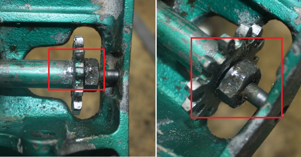
I took a file to the top one (between gear & shaft) and removed most of it. Then I put a wrench on the nut and that one broke free quite easily. From the fact the gear and nut had been tack welded for all these years, I kind of ruled out some sort of misalignment due to the handle gear (vice the release gear) moving down.

I took the entire assembly apart, cleaned it up and put it back together.


I took a file and dressed up each and every tooth on both the handle and release gear, which was probably overkill as none of them showed any wear or damage that might account for the jamming. Remember, this thing worked just fine (except for not staying up) since I had purchased it.

Then I turned to the release valve assembly to make sure it was seated fully and not held off by the valve itself, as you mentioned. I made double sure the valve itself was fully retracted, both copper rings and the steel washer (one with the square hole) properly seated. I also had the help of the green paint as I could see the valve assembly was fully seated as no unpainted threads were showing. I could also turn the release both directions, and when seated (full to the left...handle right) the jack moved up, and when turned the other way, retracted.

I then put the saddle back in place, but without the spring so I could more easily move it as I wanted to really check out the gears and how they meshed.

With the handle vertical there is no binding. As I lower the handle, when it get's to about 45 degrees (halfway between up and down) the binding starts. By the time it gets another 15 degrees lower, it jams completely. I went back and started a process of pulling up on the handle gear, rotating it one tooth, reengaging it and moving the handle down. I marked each tooth as I did this until I got through all of them. (about a beer's worth of time!)

Made no difference, still got the jamming at the same place (60 degrees down handle).

My next step is going to see if I can move one of the gears vertically to increase the clearance between them. The handle gear can be moved up by taking out the shaft and putting a washer under it. I'm not sure that will help as I really think it needs to be moved down, however that's not possible. The other possibility is to move the release up, by adding a second brass washer on top of the one in the base. It appears there is more than enough length on the valve shaft itself to allow for that.

The only other way to increase clearance is to "flatten out" the gear teeth on the release valve, but that's a last resort. Since the handle gear is flat, not much I can do there.

This thing really has me baffled and is becoming (a) a can of worms, and (b) a version of the "search for the holy grail" as now I have become determined to make it work as designed.

There is a possibility I have missed something simple, but I'll be damned if I can see it. No parts left over, worked just fine before I simply disassembled it, and there just aren't much places where it goes back together that a misalignment can take place.

Your thoughts?
 

Hiball

Well-known member
Joined
Apr 30, 2009
Messages
14,027
Location
Missery
It's damn difficult not having this thing in front of me... It's something simple, it's just a matter of figuring it out.. :rocker:

Do the shoulder bolts fit the frame tight? I wondering if there was a issue during manufacturing and maybe they oversized a side to square it up, then tack welded the body to assist in holding it.

Just a thought..
 

ROFCIBC

Member
Joined
Feb 19, 2015
Messages
19
Location
NW Louisiana
Hiball,

The alignment of the jack bottle seems right, as well as the handle saddle. The two bolts holding the bottle in the frame go right in with no problem. It's sitting on the alignment blocks welded to the frame, and the tack welds that were in place, although broken, line up. The two bolts that hold the handle saddle go right in too.

I did a measurement of the release valve cavity on the bottle and the valve itself and the numbers say it's seated properly. I made sure the valve itself was not extended to deeply when I put the assembly back in to make sure that wasn't the issue. You can see the paint on the threads also confirms it's back in its original depth.(see pix).


The jack works perfectly. Lifts, holds, retracts. The ONLY issue is that damned handle as it moves down it starts to jam and by the time its down 60 degrees (I even measured that) it is pretty much jammed and will not turn.

I did notice that when I took the release valve out, the cavity was full of fluid and some ran out. I checked and it appears the bottle is properly filled, plus I see no connection with an oil over service and the handle jamming when moved down.

I'm going to just roll it over in the corner and let it set a while. Got a trip to Daytona for the NASCAR race and will take it up when I get back.
 

anthonys1968

New member
Joined
Jun 24, 2015
Messages
4
I had the same problem with the same model 328.12001 I rotated the handle gear to a different position. and kept doing it until it worked. this might work for you?
 

ROFCIBC

Member
Joined
Feb 19, 2015
Messages
19
Location
NW Louisiana
I had the same problem with the same model 328.12001 I rotated the handle gear to a different position. and kept doing it until it worked. this might work for you?

I tried that. Pulled up the handle gear, rotated it one tooth, put it back down and still had the problem. I rotated it one tooth at a time until I had made a full 360 turn, and each time the problem was still there.
 

anthonys1968

New member
Joined
Jun 24, 2015
Messages
4
I just took mine apart again and had the same problem today.It looks like the tank moved. I had it working perfect yesterday,then i put a new rod seal in it, and the problem came back. i,m getting a new handle gear monday , maybe mine is bent. Ill keep you posted.
 

ROFCIBC

Member
Joined
Feb 19, 2015
Messages
19
Location
NW Louisiana
I just took mine apart again and had the same problem today.It looks like the tank moved. I had it working perfect yesterday,then i put a new rod seal in it, and the problem came back. i,m getting a new handle gear monday , maybe mine is bent. Ill keep you posted.

If you look back up the thread you can see where the "tank" is in the same place as before. There were small tack welds that line up perfectly, plus the two bolts that hold it in place have no adjustment capability. They are either in the hole or they are not. Same with the handle "saddle", two bolts, no adjustment.

I never thought about a new gear as I didn't think those parts were still available.

My other option (when I get back from the NASCAR race at Daytona) will be to "dress" the teeth with a grindstone and/or file.

Will post pix when I get that done. As I opined before, this has now become akin to Monty Python's "Search for the Holy Grail"! Except I'm not going to resort to the "Holy Hand Grenade!"
 

Hiball

Well-known member
Joined
Apr 30, 2009
Messages
14,027
Location
Missery
Something is a Miss, and 10-1 it has to do with those tack welds. My gut tells me that if loosen the bolt on each side of the hydraulic unit, leverage on the hydraulic unit up/down, your teeth misalignment will clear up. The single bolt system is heavily dependent on frame bars being correctly placed, my feeling is that those tack welds where in place to secure the cant (angle) due to a factory minor defect.
 
Last edited:

O'Toole

New member
Joined
Jun 26, 2015
Messages
3
I've got one of these jacks too. I bought it new, in Sears, White Plains, NY. I'm thinking 1980.
It's been fantastic--I never had any problem with it, never had to add any oil. I've only cleaned it off from time to time. Greased the saddle post, and oiled the casters, that's been it.
It seems harder to pump though, or is it my imagination? Might be my muscles aren't what they were
IMG_1736.JPG
IMG_1737.JPG
 

anthonys1968

New member
Joined
Jun 24, 2015
Messages
4
There are no bolts holding the hyd unit that I can see only two bars on each side locating it, I hit the bottom of the hyd unit with a large hammer and it moved up enough to engage the gears. It now works. i think i will have to tack weld it in place. Are the bolts holding the hyd unit on you are reffering to the ones holding the wheels on. I also see no tack welds on mine.I just checked the bolts , they were loose !!!
 
Last edited:
To avoid these ads, REGISTER NOW!
Top Bottom