To avoid these ads, REGISTER NOW!

Wiring magnetic (definite purpose) starters for compressor?

Greg9504

Well-known member
Joined
Dec 19, 2007
Messages
47
Location
Ottawa, Ontario, Canada
Hi,

I picked up a used 7.5 hp compressor (Snap-On, however it's actually an Eagle 7180V2-MS painted red with Snap-on logo). However it did not have a magnetic starter included. I purchased a magnetic starter from Princess Auto (think Harbor Freight but Canadian), that their catalog recommends for a 7.5 hp compressor. It is a D Square 8911 DPSO43 (1 or 3 phase, 3 pole), with a 9998 DA1VO2 coil (120v), and a B 40 thermal unit (to install in the starter, may be referred to as a "heater"). I haven't been able to find much in the way of documentation beyond the general specifications. So from surfing the web I think I have it figured out, but I would like to go over the wiring as there are a few terminals which I am unsure of their function (OL and COM).

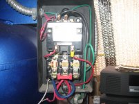
Here's an over all picture. The thermal unit can be seen on the left.
magnetic_starter_1.JPG


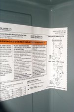
The wiring diagram included in the cover:
magnetic_starter_4.jpg


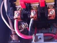
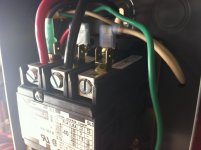
The coil terminals (for those reading this trying to figure out the inside of their starter, the coil here is the two spade terminals, one has a red wire connected to it in the picture below. When the coil is energized (by the pressure switch turning on), this moves the magnet, completing the circuit starting the motor... I think ).
magnetic_starter_2%20_Large.jpg


Mine are labeled A1 and A2, A1 has the red wire on it which goes to a terminal at the bottom labeled OL.

magnetic_starter_3%20_Large.jpg

The terminal with the red wire attached is labeled OL, the one below it is labeled COM. Not sure what part of the starter this is or what function it serves, anyone?

OK so here is what I think I need to do:
main power comes in and one side goes to L1, one to L2. The thermal unit is installed at T1 to connect T1 to the upper part of the switch, a jumper wire is installed at T2. T1 and T2 then go to the motor. Now for the pressure switch. Run a wire from L1 to the switch, then from the switch to A2 (the free terminal on the coil). Does this sound right?

Thanks
Greg.
 
To avoid these ads, REGISTER NOW!

s_ontario

Well-known member
Joined
Jan 5, 2006
Messages
552
Location
canada
This is what i found Not 100% sure its correct but I'll post the picture and perhaps someone else can confirm it for you

1phasemagstarterqt0.jpg


I call my dealer and he talked me out of getting a Mag starter said he had 3 units in my area none with a mag starter and he knows ones been out for 20 years and never had a starter
 
OP
G

Greg9504

Well-known member
Joined
Dec 19, 2007
Messages
47
Location
Ottawa, Ontario, Canada
I call my dealer and he talked me out of getting a Mag starter said he had 3 units in my area none with a mag starter and he knows ones been out for 20 years and never had a starter

Thanks for the schematic...

If I remember correctly from your post in the air compressor thread you own a 5 hp unit, he probably recommended that to you because your pressure switch is rated for the amps for your motor. The motor on mine is 35.5 amps (SF of 40 Amps). The pressure switch is only rated for 20 amps. So I could find a pressure switch rated for 40 amps or spend the same money on a mag starter and get the added bonus of overload protection for the electric motor.

Once I got a hold of some industrial circuit symbol definitions all fell into place.

There are basically 3 parts to the "magnetic starter". The coil/magnet (this is terminal A1 and A2), the contactor (L1 and L2), and the overload protection (OL and COM terminals).

The coil can be either 120V or 240V. If your starter has a 120V coil you'll need to use a 3 wire (plus ground) supply cable, since you'll need the neutral for 120V.

So then, how to wire it.
Supply.
Bring in the supply, L1 and L2 get power (black and red wire), neutral (white) goes to "COM" terminal at the bottom (overload relay). I had to use an insulated twist connector to connect a 14 gauge wire to the supply neutral wire, then to the COM terminal. Since my supply was 8 gauge and the COM terminal was too small. And of course bare wire to ground.

Pressure switch.
You'll need a 2 wire cable (plus ground) to go to the pressure switch. For the starter to operate, the coil needs 120V. So a wire is run from L1 (Use one of the spade connectors at L1) to the "LINE" terminal on the pressure switch, then from "MOTOR" terminal on the switch back to A2 (other side of the coil).

Overload.
A1 on the coil is wired from the factory to the OL (Over Load) terminal on the overload part of the starter. If the overload relay trips, the connection between A1 and neutral (COM terminal) is broken and the motor wont start.
Overload relays (referred to as "heaters"), If your starter uses these you'll need one for a single phase motor, the documentation for the starter will give you details on which one to get (mine required a B50). You'll also need some jumpers, hopefully your starter will come with the jumpers. Mine is a polyphase unit (it can be used for a single or three phase motor), and didn't come with any jumpers. I couldn't find any jumpers so that's why you see three relays in the attached picture. The starter WILL NOT WORK without the jumpers. If you don't have the jumpers in, the overload protection appears tripped, and therefore no current across the coil.

Motor.
T1 and T2 on the starter go to the motor.


If you have a 240V coil L2 will connect to "COM" of the overload protection circuit and you can run a 2 conductor (plus ground) from your panel instead of a 3 conductor since you wont need a neutral for a 120V circuit. Otherwise you connections should be the same.

magnetic_starter_wire_connections_120V_coil%20(Large).jpg


magnetic_starter_pressure_switch_120V%20(Large).jpg


jumpers
squared-9998SO31.jpg
 
Last edited:

BradIXXI

New member
Joined
Nov 18, 2008
Messages
1
This is what i found Not 100% sure its correct but I'll post the picture and perhaps someone else can confirm it for you

1phasemagstarterqt0.jpg


I call my dealer and he talked me out of getting a Mag starter said he had 3 units in my area none with a mag starter and he knows ones been out for 20 years and never had a starter

Great image. What would it look like for three phase?
I have a Square D (part# 8536scg3v02s) and the diagrams are useless to me on how, or more spacific, where to connect my preausure switch.
Any help would be great.
Kind Regards,
Brad
 
OP
G

Greg9504

Well-known member
Joined
Dec 19, 2007
Messages
47
Location
Ottawa, Ontario, Canada
According to the specs (see here) the coil (V02S) on the starter is 120V from a separate source. So you'll need to bring in the 3 phase power for the motor and a separate 120v single phase source to go between the coil and the pressure switch... at least that's my GUESS without seeing the wiring diagram included with the starter.
Get the part number off the coil and do a search on it.
 

Charles (in GA)

Well-known member
Joined
Jan 11, 2006
Messages
12,489
Location
50 mi south of Atlanta
Look at this thread for a pic of my Square D starter on a 7.5 hp Husky/C-H compressor. There is another post, with a better description of the wiring inside of the starter, I'm still looking for it.

http://www.garagejournal.com/forum/showthread.php?t=456

EDIT: found it......

http://www.garagejournal.com/forum/showthread.php?t=22949&highlight=magnetic+starter

See my post #8 in the above thread, for my description of the wiring in my Square D starter. It is the des of the wiring in the starter pictured in the top thread link, my post #6.

Charles
 
Last edited:

larbow

New member
Joined
Nov 29, 2009
Messages
3
Location
Hanna Wy.
The wire that needs to go to COM should I run that back to my breaker box and give it it's own source. That seems to be my only loose wire that needs to be connected to something I think.
It's connected to the COM and connected to nothing on the other.
 
OP
G

Greg9504

Well-known member
Joined
Dec 19, 2007
Messages
47
Location
Ottawa, Ontario, Canada
I can only guess because you haven't provided enough information.

So I'm assuming single phase. Did you run a 3 conductor (plus ground) from the panel to the starter? Or a 2 conductor (plus ground)? Is your coil 120v? if it is:

The coil can be either 120V or 240V. If your starter has a 120V coil you'll need to use a 3 wire (plus ground) supply cable, since you'll need the neutral for 120V.

neutral = COM

In my picture the large white supply wire is connected to COM (Neutral on the panel).

I'm guessing again that you ran a 2 wire cable so you have no neutral. Could your run another wire from your neutral tap on the panel to the starter? Probably wouldn't pass inspection.
 

Thedroid

Well-known member
Joined
Feb 16, 2009
Messages
718
Location
New Mexico
3 phase will have L1, L2, and L3 coming in the top, T1, T2, and T3 going out to the motor. You will then hook up an additional wire to L1 and L2 and connect them to a control transformer that matches the voltage on the starter coil. Everything else is hooked up the same, making sure that all of the power going through the control circuit is coming from the secondary of the control transformer. Always run the neutral through the O/L also.

The one thing I hate about the Square D relays, is that red wire hooked up to A1 from O/L. Should be a white wire hooked up to A2 IMO. Electrically it doesn't matter, but it should be white.
 

larbow

New member
Joined
Nov 29, 2009
Messages
3
Location
Hanna Wy.
Yes I'm using single phase. It has a 120v coil.
I've got my power wires connected to L1 and L2 and a ground.
I have a 14 gauge wire going from L1 to the line terminal on the pressure switch and a wire coming off the pressure switch to 3 terminal which then goes to the coil. coming out the other side of the coil is another wire that goes to the OL.
I ran a seperate wire from my breaker box to the COM.
But I'm not sure if I'm connected to the right place in my breaker box.
When I turn the power on it trips the breaker instantly.
 

Attachments

  • IMG_1410.jpg
    IMG_1410.jpg
    146.5 KB · Views: 337
  • IMG_1412.jpg
    IMG_1412.jpg
    142.3 KB · Views: 250
  • IMG_1413.jpg
    IMG_1413.jpg
    129.1 KB · Views: 225
  • IMG_1415.jpg
    IMG_1415.jpg
    126.6 KB · Views: 212

Thedroid

Well-known member
Joined
Feb 16, 2009
Messages
718
Location
New Mexico
Where is the wire from the panel to common hooked up to? It should be hooked up with all the other white wires, and definitely not hooked up to a breaker. You might want to call an electrician to give you a hand hooking that up. You don't want the risk of a fire or electrocution in the future.
 
Last edited:

Thedroid

Well-known member
Joined
Feb 16, 2009
Messages
718
Location
New Mexico
L2 is for your motor, and without re reading the post I remember this being a 240V motor. If this is the case, then I'm not surprised that the breaker is tripping. COM should be hooked up to A2 for the coil, definitely not L2.
 
To avoid these ads, REGISTER NOW!

Thedroid

Well-known member
Joined
Feb 16, 2009
Messages
718
Location
New Mexico
After you sort that out, if the breaker is still tripping you can disconnect the neutral, and check the rest of the circuit to ground using your multimeter set to read resistance. You should not read anything to ground.

Remember, you are dealing with 2 different circuits here. One is the power circuit for the motor, the other is your control circuit.
 

JohnJL

Well-known member
Joined
Jul 28, 2010
Messages
150
Location
Toronto
Greg, did you get everything running? I'm in the same boat...need to wire up my 220V 1-phase motor with a mag starter and pressure switch...

Do you have a diagram? That would be awesome.

John
 
OP
G

Greg9504

Well-known member
Joined
Dec 19, 2007
Messages
47
Location
Ottawa, Ontario, Canada
Yes it's been running fine. I don't have a wiring diagram. Look on the inside of your starter, that should get you started. Then you need to know if you have 120v coil or a 220v one. Hopefully with my description above and the pictures (the wires are labeled in the picture) you should be able to sort it out.
 

JohnJL

Well-known member
Joined
Jul 28, 2010
Messages
150
Location
Toronto
I actually have the exact same starter as you and a similar motor and switch.

I couldnt ascertain from your pics/description...

1. Is the heater necessary and where did you install it in the SquareD starter? Mine had no documentation with it.
2. I only see 2 white wires pigtailed together, and your pic refers to "com" as one of those. I dont see a "com" terminal in the starter, is it one of the clear terminals or somehting else?
3. Where did you get those jumpers? Im also in Toronto.
4. How many wires did your motor have? Mine has 2 heavy wires labelled "1" and "4" and 2 ligher gauge wires labelled "5" and "8." The motor wiring diagram only indicates to wire 1 and 5 together and 4 and 8 together. I emailled tech assist from Baldor but they gave me a lame "we didnt make the compressor so we dont know the wiring requirements" response, even though my question was very specific to their motor...
 
OP
G

Greg9504

Well-known member
Joined
Dec 19, 2007
Messages
47
Location
Ottawa, Ontario, Canada
Hi John,

Slow down and re-read, all your questions were already answered above. Press Ctrl and + keys at the same time to increase the size of the images.

1) As I said the "heater" is a relay. It is 100% absolutely necessary. Without it (if you just jumped all 3 terminals) you would have no overload protection. There is only one place the heaters can go. They are installed in the picture that has the wires labeled. They are not installed in the first picture of the starter. They must be sized to the motor you are running, I believe on the inside of the cover there should be a chart with the sizes. I don't have a picture, but in the one I attached to this post the chart would be to the left. Use the wrong size and you could have a fire, or always be tripping the breaker.
attachment.php

2) Look closer, the com terminal is one of the clear plastic ones at the bottom of the starter. It is labeled.
3) as I said in my post, I couldn't find anyone stocking the jumpers here in Ottawa. So I just used heaters instead for the terminals that didn't require a relay. I got them at Princess Auto.
4) I can't tell you that. I can only offer a guess... you have two heavy gauge wires (plus ground) leaving the starter... that leaves you with only one place for them to go on the motor...

Ultimately if you don't feel comfortable wiring the starter, hire an electrician.
 

Attachments

  • magnetic_starter 015 (Large).jpg
    magnetic_starter 015 (Large).jpg
    58.2 KB · Views: 1,079

JohnJL

Well-known member
Joined
Jul 28, 2010
Messages
150
Location
Toronto
Thanks Greg. Since I've never held a heater in my hand I didnt recognize their "backsides" in the labelled picture.

Also, though we have the same model number starter unit, my COM terminal was not labelled. Your pic clarified that.
 
OP
G

Greg9504

Well-known member
Joined
Dec 19, 2007
Messages
47
Location
Ottawa, Ontario, Canada
Hi John, Look closely the com terminal should be labeled, might be a symbol.

Here are some pictures for further clarification. Two are of the bottom where the com terminal is, the other is of the top.
 

Attachments

  • magnetic_starter_new_001.jpg
    magnetic_starter_new_001.jpg
    164.1 KB · Views: 108
  • magnetic_starter_new_003.jpg
    magnetic_starter_new_003.jpg
    146.1 KB · Views: 111
  • magnetic_starter_new_002.jpg
    magnetic_starter_new_002.jpg
    140.8 KB · Views: 114

JohnJL

Well-known member
Joined
Jul 28, 2010
Messages
150
Location
Toronto
Hi John,


Ultimately if you don't feel comfortable wiring the starter, hire an electrician.

Also, I'd have to hire OTHER electricians...I asked my regular guys who were on site to install the mains and lighting, they had no idea about the compressor/motor/switch wiring....

In any case I enjoy the challenge of learning something new about how to wire and set up machinery...If I just hired an electrician I wouldnt have the same learning experience which I enjoy. Even if it means I have to keep asking you guys questions...
 

JohnJL

Well-known member
Joined
Jul 28, 2010
Messages
150
Location
Toronto
Hi John, Look closely the com terminal should be labeled, might be a symbol.

Here are some pictures for further clarification. Two are of the bottom where the com terminal is, the other is of the top.

Awesome, thanks.
 

JohnJL

Well-known member
Joined
Jul 28, 2010
Messages
150
Location
Toronto
The coil can be either 120V or 240V. If your starter has a 120V coil you'll need to use a 3 wire (plus ground) supply cable, since you'll need the neutral for 120V.

I think you mean you need 3-wire if its a 240v coil? 120v would just need 2-wire (black = hot, white = neutral, bare = ground)

I've been trying to wrap my head around these...
 

george.dickinson

New member
Joined
Sep 21, 2015
Messages
1
Thanks for the schematic...

If I remember correctly from your post in the air compressor thread you own a 5 hp unit, he probably recommended that to you because your pressure switch is rated for the amps for your motor. The motor on mine is 35.5 amps (SF of 40 Amps). The pressure switch is only rated for 20 amps. So I could find a pressure switch rated for 40 amps or spend the same money on a mag starter and get the added bonus of overload protection for the electric motor.

Once I got a hold of some industrial circuit symbol definitions all fell into place.

There are basically 3 parts to the "magnetic starter". The coil/magnet (this is terminal A1 and A2), the contactor (L1 and L2), and the overload protection (OL and COM terminals).

The coil can be either 120V or 240V. If your starter has a 120V coil you'll need to use a 3 wire (plus ground) supply cable, since you'll need the neutral for 120V.

So then, how to wire it.
Supply.
Bring in the supply, L1 and L2 get power (black and red wire), neutral (white) goes to "COM" terminal at the bottom (overload relay). I had to use an insulated twist connector to connect a 14 gauge wire to the supply neutral wire, then to the COM terminal. Since my supply was 8 gauge and the COM terminal was too small. And of course bare wire to ground.

Pressure switch.
You'll need a 2 wire cable (plus ground) to go to the pressure switch. For the starter to operate, the coil needs 120V. So a wire is run from L1 (Use one of the spade connectors at L1) to the "LINE" terminal on the pressure switch, then from "MOTOR" terminal on the switch back to A2 (other side of the coil).

Overload.
A1 on the coil is wired from the factory to the OL (Over Load) terminal on the overload part of the starter. If the overload relay trips, the connection between A1 and neutral (COM terminal) is broken and the motor wont start.
Overload relays (referred to as "heaters"), If your starter uses these you'll need one for a single phase motor, the documentation for the starter will give you details on which one to get (mine required a B50). You'll also need some jumpers, hopefully your starter will come with the jumpers. Mine is a polyphase unit (it can be used for a single or three phase motor), and didn't come with any jumpers. I couldn't find any jumpers so that's why you see three relays in the attached picture. The starter WILL NOT WORK without the jumpers. If you don't have the jumpers in, the overload protection appears tripped, and therefore no current across the coil.

Motor.
T1 and T2 on the starter go to the motor.


If you have a 240V coil L2 will connect to "COM" of the overload protection circuit and you can run a 2 conductor (plus ground) from your panel instead of a 3 conductor since you wont need a neutral for a 120V circuit. Otherwise you connections should be the same.

magnetic_starter_wire_connections_120V_coil%20(Large).jpg


magnetic_starter_pressure_switch_120V%20(Large).jpg


jumpers
squared-9998SO31.jpg
The Older SnapOn Compressors have a problem with vibration doing in the electronics required to operate the Compressor. I have a Model AC580V S/N J3821. I was able to resolder the part of the board that cam loose and it is now working but would like to get the details from a vendor who could supply the motor starter in box pictured in Greg9504 post; with pricing etc. as I am convinced that it is the way to go with the vibration issues. I am trying to keep the cost down. My motor is rated at 30 amps. I am new to this format so I hope posting it here is "OK"
 

930cabman

Member
Joined
Apr 29, 2017
Messages
9
We recently purchased an older Hitachi B 600a band saw at auction. The motor was cooked so we added a 5hp 240v 3 phase motor with a new Square D " definite purpose" starter. The starter was sent from Amazon without a wiring diagram for the control circuit. I requested one from Amazons supplier and was told to connect L1 and L3 across the switch terminals. Would this create a 240V condition at the switch? Our other 3 phase equipment is switched with an off momentary contact n/c and an on momentary contact n/o. Is a definite purpose perhaps not correct for our application?
 

jusbrock

New member
Joined
May 29, 2013
Messages
1
He means if your coil is 120v you will need a 3 wire + ground coming from panel. 2 power,1 neutral, 1 ground. The neutral is for the coil.
 
To avoid these ads, REGISTER NOW!
Top Bottom