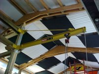
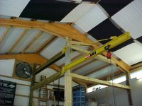
After about 2 months of weekends building the structure to hold it, I finally hoisted up the crane and mounted it last weekend. It has a 10 foot span and the beam is over 13 feet high. It's definitely going to expand the capabilities inside my shop and I couldn't be happier with the results. You can see more pictures and read about more of the construction details at the link in my signature or go to the Garage Gallery and look for the ASYLUM.


You are using an out of date browser. It may not display this or other websites correctly.
You should upgrade or use an alternative browser.
You should upgrade or use an alternative browser.
The JIB CRANE is finally up!
- Thread starter shopnut
- Start date

Ign
Well-known member
Love the crane. Have you run calcs on the load? I have no formal engineering experience but the copious use of wood makes me nervous. How much would you feel comfortable having on the hook at the furthest distance from the mounting point?
W the Dayton stickers the crane looks production? How much did it set you back?
W the Dayton stickers the crane looks production? How much did it set you back?
autoclassicnut
Well-known member
First sight had me thinking same thing, trust the steel but check out the rating of load capacity of the wood, Looks scary, last thing you want is the sound of wood and steel crashing down.
comp
Well-known member
how much have you tested it at ??
I checked the full thread and I like the reinforcing you did to the vertical post.
The stress on the beams at the bottom pivot will change from tension to compression as you swing a load around the circle. If you get any deflection a diagonal from the post to the building corner should triangulate it and stiffen it quite a bit.
At the very top of the post extra support by filling in the ridge triangles and a tension cable from the post down to the building corner and you should be at full rating.
Very nice job.
It will change they way you work and make life easier for you and your “helpers.”
The stress on the beams at the bottom pivot will change from tension to compression as you swing a load around the circle. If you get any deflection a diagonal from the post to the building corner should triangulate it and stiffen it quite a bit.
Actually, just going by the pictures and without doing any real analysis, the beams on the bottom pivot should not see any compression or tension forces. The only way that this could occur is if he somwhow applied a side load, but all of his loads will be vertical. These vertical forces will be transferred to the ground through the column. These horizontal support beams at most might get some of the moment transferred through them from the fixed support.
The horizontal beams at the top connection will most likely see some tension forces only due to the crane's support tension member which will change some of the vertical forces into horizontal forces causing the tension.
The crane looks really nice...but if you start to hear splintering when you apply a heavy load, get the hell out of there.
All kidding aside, I would definitely get that analyzed by a professional engineer before you do any serious work, so you know the safe limitations for that crane.
D KRAGER
Well-known member
I saw in your other post that it would have a 1 ton chain hoist. I would say no problem with that load. Looks like you have braced it well. For the setup to fail, the whole building would have to collapse. I think it looks great!
joecaver
Well-known member
WOW!! That is a very impressive installation. It looks like you've really put a lot of thought into not just the crane but the entire shop. Very nice 
Let it be known that a wall mounted jib crane puts a tremendous load on it's mount points. Think of it as a big lever arm and the further the load is from the post or wall its mounted to, the longer the lever arm.
With a load rolled to the outer outer end of the I-beam, it converts this vertical load being lifted into very high tensile (on top mount) and compressive (on bottom mount) loads acting mainly horizontally on the pivot pins. There is still a combined vertical load on the mounts that equals the lifted load plus the weight on the crane itself and the top mount sees a majority of that.
On the other hand, with the load rolled over close to the wall, the load loses most of it's "leverage" on the wall and the horizontal loads reduce significantly. The lower mount now sees nearly all of the load in a vertical direction
Here are some numbers from the professional engineer to give you an idea:
1000 pound load at outer end:
Top mount - 3550# horizontal (tension), 1110# vertical
Bottom mount - 3550# horizontal (compression), 130# vertical
1000 pound load 12" from post:
Top mount - 700# horizontal (tension), 220# vertical
Bottom mount - 700# horizontal (compression), 1020# vertical
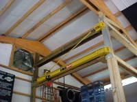
In my particular installation, when swinging the crane from one side to the other, the loads do, in fact, reverse from compression to tension on the two darker-colored beams (connecting to the post by the exhaust fan) as the crane swings through it's half circle. They reverse at the point when the crane is at 90 degrees where the loads in the dark beams (top and bottom) essentially drop to zero. I just wanted to clarify this point as there was some controversy above. Also, my particular installation is a bit weaker at the 0 and 180 degree positions than in the middle of the swing due to my non-symetrical structure, but I will keep that in mind as I'm using it.
Lastly, rest assured I will be the first one running if I here splintering wood!
With a load rolled to the outer outer end of the I-beam, it converts this vertical load being lifted into very high tensile (on top mount) and compressive (on bottom mount) loads acting mainly horizontally on the pivot pins. There is still a combined vertical load on the mounts that equals the lifted load plus the weight on the crane itself and the top mount sees a majority of that.
On the other hand, with the load rolled over close to the wall, the load loses most of it's "leverage" on the wall and the horizontal loads reduce significantly. The lower mount now sees nearly all of the load in a vertical direction
Here are some numbers from the professional engineer to give you an idea:
1000 pound load at outer end:
Top mount - 3550# horizontal (tension), 1110# vertical
Bottom mount - 3550# horizontal (compression), 130# vertical
1000 pound load 12" from post:
Top mount - 700# horizontal (tension), 220# vertical
Bottom mount - 700# horizontal (compression), 1020# vertical
In my particular installation, when swinging the crane from one side to the other, the loads do, in fact, reverse from compression to tension on the two darker-colored beams (connecting to the post by the exhaust fan) as the crane swings through it's half circle. They reverse at the point when the crane is at 90 degrees where the loads in the dark beams (top and bottom) essentially drop to zero. I just wanted to clarify this point as there was some controversy above. Also, my particular installation is a bit weaker at the 0 and 180 degree positions than in the middle of the swing due to my non-symetrical structure, but I will keep that in mind as I'm using it.
Lastly, rest assured I will be the first one running if I here splintering wood!
Last edited:
Shopnut,
Sorry, I didn't mean to cause controversy or sidetrack this thread. I just saw some information posted above that was incorrect and thought I would correct.
KBS said that the horizontal beams on your bottom pivot will experience both compression and tension as you rotate the crane about its axis. I said that these beams should not see any axial forces because they should be transferred to the ground through the main column. I will stand corrected that there is a chance that they could see some compressive forces, but only if your main column has a low enough moment of inertia to allow some deflection at this location. Most jib cranes are overbuilt at these connection points, so that the main column will not deflect (under safe crane loads) which requires no members behind these areas, and the forces will transfer the base of the unit.
So that being said, I could maybe see these members experiencing some compression forces, but as you swing the crane around its axis, these forces should go zero or nuetral, not tension. You could say the exact opposite is true for the horizontal beams connected to the top support. If anything, they may see tensile forces only. Again it all depends on the moment of inertia for the main column which by the looks of will be different based on which axis you are analyzing. I am sure your engineer has done all of these calcs for you so he should be able to tell you for sure.
Again, sorry for any confusion or controversy. I am glad that you have had it analyzed by a PE, not only for your safety, but also because it keeps us in business , Thanks.
To get this thread back on track, I will end this by saying your crane looks very nice, and from the pictures the craftsmanship looks excellent. Good Job.
Sorry, I didn't mean to cause controversy or sidetrack this thread. I just saw some information posted above that was incorrect and thought I would correct.
KBS said that the horizontal beams on your bottom pivot will experience both compression and tension as you rotate the crane about its axis. I said that these beams should not see any axial forces because they should be transferred to the ground through the main column. I will stand corrected that there is a chance that they could see some compressive forces, but only if your main column has a low enough moment of inertia to allow some deflection at this location. Most jib cranes are overbuilt at these connection points, so that the main column will not deflect (under safe crane loads) which requires no members behind these areas, and the forces will transfer the base of the unit.
So that being said, I could maybe see these members experiencing some compression forces, but as you swing the crane around its axis, these forces should go zero or nuetral, not tension. You could say the exact opposite is true for the horizontal beams connected to the top support. If anything, they may see tensile forces only. Again it all depends on the moment of inertia for the main column which by the looks of will be different based on which axis you are analyzing. I am sure your engineer has done all of these calcs for you so he should be able to tell you for sure.
Again, sorry for any confusion or controversy. I am glad that you have had it analyzed by a PE, not only for your safety, but also because it keeps us in business
, Thanks.To get this thread back on track, I will end this by saying your crane looks very nice, and from the pictures the craftsmanship looks excellent. Good Job.
Thanks for your comments, Bigvic.
One thing not mentioned in this thread is that this crane framing will also end up being the wall framing, at least partially, for the upstairs office and minimal (read negligible) deflection on the vertical column is desired where the door at the base of the stairs will be located. If interested (or bored) my main thread in the Gallery summarizes my future intentions in this part of the building. These horizontal beams were put in to "stabilize" the column. If a large load were placed on the crane at it's outer tip in the 90 degree position for instance, the column would bow in slightly and distort (reduce) my door opening witdh, which is not good. The light-colored beams (heading over to the clerestory windows) with the crane at 90, reduces or virtually eliminates the vertical moment induced in the column by the cantilevered load.
The dark-colored horizontal beams, heading towards the exhaust fan, only serve to stabilize the column when it is rotated in either direction from the center 90 degree position.
Normally these jib cranes are bolted to the steel columns within a factory and not to wooden columns so in this case, extra precautions were recommended.
If you still don't agree with all this, voice your opinion and I will take it up with the PE. Safety, of course, is my main concern when dealing with these overhead lifting devices.
buening
Well-known member
For wood construction, I would have to say this is well executed! I'm a structural engineer in Illinois, and it appears you have it braced correctly. I haven't ran any numbers on it, but bracing is in the correct location. Something commonly overlooked and are trouble areas are the detailing, i.e. spacing/size/number of bolts and bearing plate size/thickness. I'm sure the PE had this all covered when he did the plans.
buening
Well-known member
Out of curiosity, what type of wood was used for the column and bracing? Hardwood would add extra factor of safety to the design. One thing I may warn you (if the PE did not), be very careful to keep the large loads at the outer end of the boom stable. Bouncing or catching a heavy weight (say removing motor mounts and relying on the crane to catch the motor) adds extreme weight to your crane. While you may say this is common sense, it can be overlooked by some. Just keep in mind the design was likely done for static loading and not dynamic
Out of curiosity, what type of wood was used for the column and bracing? Hardwood would add extra factor of safety to the design.
All framing material was pressure treated lumber (I believe pine). I agree with the use of hardwood and I'm all for the extra safety factor, but it is just not as readily available.
Thanks for the vote of confidence and the warnings.
Uncle Buck
Banned
I think it looks highly beneficial and well thought out!