To avoid these ads, REGISTER NOW!

Connecting stator windings Craftsman 1-phase capacitor start motor 110v

ilya

Well-known member
Joined
Jul 9, 2008
Messages
108
Location
Santa Monica, CA
This motor came with the drill press I purchased a few months ago and when I took it apart for cleaning and bearing replacement, I did not fully label the wires going from stator to the terminals. I could use some help in figuring out how to connect the stator windings. Below are some photos and additional information.

Thanks!
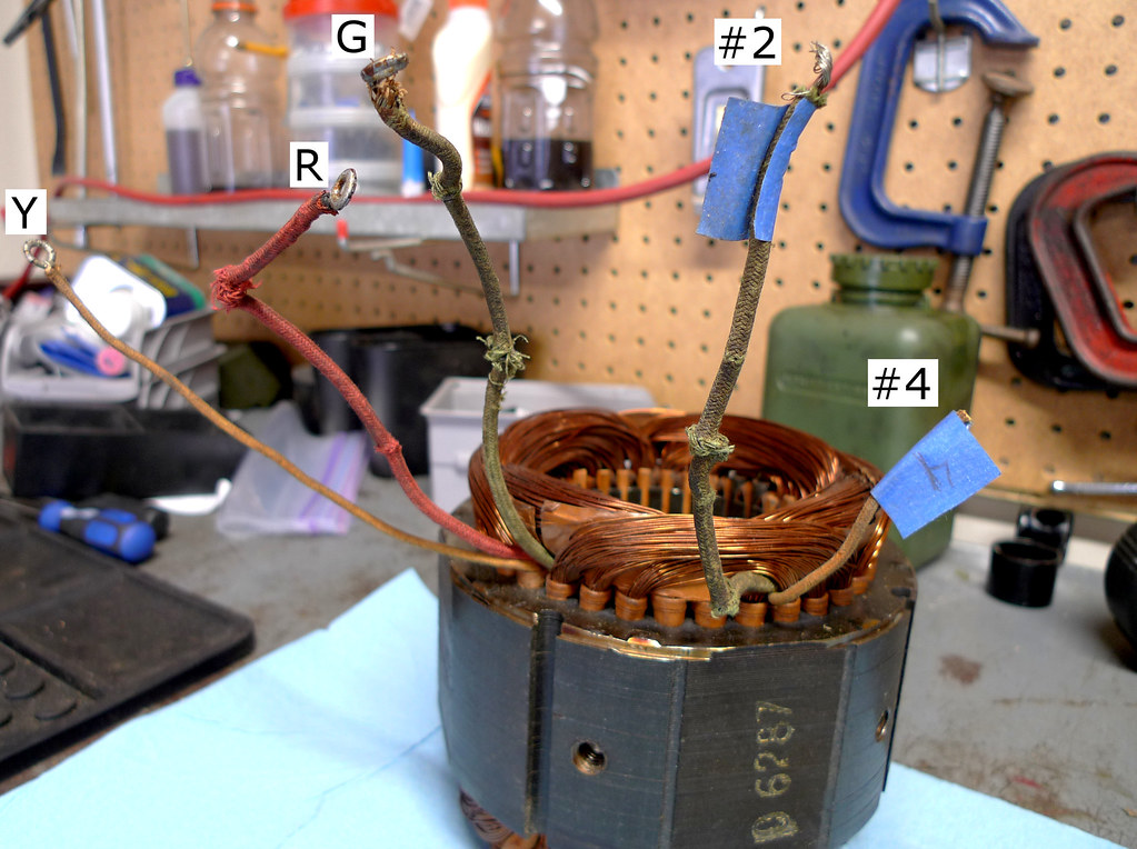
9204273713_1c3e01e0d5_b.jpg

1. Stator. Wire labeled #4 connects to capacitor. Wire #2 I think connects to neutral (based on some forum posts of people having similar problem)

Table showing resistance measurements of stator wires
Code:
+------------+-----------+--------+------------+-----+-----+
|            | Green (G) | Red(R) | Yellow (Y) | #2  | #4  |
+------------+-----------+--------+------------+-----+-----+
| Green (G)  | XXXXXXXXX | 1.5    |            | 0.6 |     |
| Red (R)    | 1.5       | XXXXXX |            | 1.5 |     |
| Yellow (Y) |           |        | XXXXXXXXXX |     | 7.3 |
| #2         | 0.6       | 1.5    |            | *** |     |
| #4         |           | 7.3    |            |     | *** |
+------------+-----------+--------+------------+-----+-----+

From the above it seems that Green + Red are the run winding and Yellow + #4 are the start winding. Does it make sense that cable #2 connects to neutral and that there's resistance between it and Green and Red wires?

Additional photos:

9172131550_29fc8af4a9_b.jpg

2. Name plate. Based on the instructions for reversing the motor, it looks like yellow leads from centrifugal switch and stator Yellow wire connect to different terminals and it doesn't matter which ones. If it runs in reverse, I can always switch them.

9172132748_c0d81ffeb6_b.jpg

3. Toggle switch. 1 wire connects to hot, the other to thermal reset switch

9172134698_0d690a5e8d_b.jpg

4. Thermal reset switch. One wire connects to toggle switch.

9172135720_b772b6e5e5_b.jpg

5. Capacitor. One wire connects to wire #4 on stator, the other to centrifugal switch.

9169915187_8e87dd4741_b.jpg

6. Centrifugal switch. One wire connects to capacitor, the other to one of the terminals. Which one?

9172133928_4ee0b0d701_b.jpg

7. Terminal plate.

9172137480_709459d448_b.jpg

8. Rotor
 
To avoid these ads, REGISTER NOW!

jtbinvalrico

Well-known member
Joined
Jan 2, 2010
Messages
1,375
Location
Tampa FL
I can help with this. I'm fairly certain I've got an extra motor just like yours disassembled in a box, but with all the wires hooked up. It'll be a few days though before I can get out there and take some photos for you.

:beer:
 
OP
I

ilya

Well-known member
Joined
Jul 9, 2008
Messages
108
Location
Santa Monica, CA
I can help with this. I'm fairly certain I've got an extra motor just like yours disassembled in a box, but with all the wires hooked up. It'll be a few days though before I can get out there and take some photos for you.

:beer:

Thank you very much! Only if it's not too much trouble.
 

Davefr

Well-known member
Joined
Jan 7, 2010
Messages
11,855
Location
OR
Something's wrong with your chart:

Line 2 shows no reading for #4 to Red.

Line 4 shows 7.3 ohms Red to #4

Which is it??
 

mm08822

Well-known member
Joined
Jan 13, 2012
Messages
6,072
Location
NJ
Seeing pics of this motor took me down memory lane of rebuilding an old craftsman tablesaw of my dad's! It had the 3/4hp version of this motor - 1952 vintage.
Check out my sketches - first page shows all connections for this type of motor. Second page shows what you have and seems to confirm the readings you took.

Good luck!
 

Attachments

  • Single_Phase_Cap_Motor.pdf
    45.5 KB · Views: 179
OP
I

ilya

Well-known member
Joined
Jul 9, 2008
Messages
108
Location
Santa Monica, CA
I'm sorry about the confusion. I double checked the resistance readings this morning (duplicates removed):

Code:
Yellow <-> #4 = 7.3

Red <-> Green = 1.5
Red <-> #2 = 1.5

Green <-> #2 = 0.6
 
To avoid these ads, REGISTER NOW!

mm08822

Well-known member
Joined
Jan 13, 2012
Messages
6,072
Location
NJ
I missed that data point in the original data presented that Davefr found to be in conflict. I think you just recorded the result in the wrong column -red instead of yellow. Your new data reported fixes his concern and agrees with my info.
 

Davefr

Well-known member
Joined
Jan 7, 2010
Messages
11,855
Location
OR
Seeing pics of this motor took me down memory lane of rebuilding an old craftsman tablesaw of my dad's! It had the 3/4hp version of this motor - 1952 vintage.
Check out my sketches - first page shows all connections for this type of motor. Second page shows what you have and seems to confirm the readings you took.

Good luck!


That sketch looks right.
 
OP
I

ilya

Well-known member
Joined
Jul 9, 2008
Messages
108
Location
Santa Monica, CA
It's alive! It's alive!

After several months I finally found enough motivation to work on the motor again. I replaced the wiring using plenty of solder and heat-shrink tubing, and assembled the motor following the instructions in this post:

http://www.owwm.org/viewtopic.php?f=1&t=114313&p=771398&hilit=craftsman+stator#p771398

After flipping the switch the motor emitted humming noise without any rotor movement. After I flipped the switch while giving the rotor a spin, the motor started. It ran for a minute or two when I began hearing some noise from the centrifugal switch side of the rotor. I stopped the motor and observed that one side of the rotor shaft (the one from where the noise originated) was noticeably warmer than the other side.

After some deliberation I decided that I haven't pressed one of the bearings far enough on the rotor. Using an elaborate combination of 1/2" sockets and a 12-ton HF hydraulic press, I was able to seat the bearing fully on the rotor shaft. I quickly assembled the motor and gave it another go... Et voilà! the motor started on its own, running for several minutes without any noises. After stopping it both ends of the rotor shaft were equally cold.

Now I just need to figure out whether to use the vari-slo or to attempt making some kind of a jackshaft in order to slow the spindle down for metal work.

Thank you very much jtbinvalrico for photos and mm08822 for diagrams, I don't think I'd have been able to put the motor together without your help!
 

pattenp

Well-known member
Joined
Jun 4, 2008
Messages
10,175
Location
Virginia - USA
I'm surprised that old sardine can capacitor is still good. I have that same motor on an old table saw and had to replace the cap with a round style mounted on the outside of the case because the sardine can style was not available anymore.
 
To avoid these ads, REGISTER NOW!
Top Bottom