To avoid these ads, REGISTER NOW!

Old AC motors, shed some light

FunkyfullWidth

Well-known member
Joined
Oct 3, 2011
Messages
1,238
Location
Three Rivers, ma
I've run into it a couple of times now. I get an old ac motor, and have no clue on how to hook it up. I've come from the school of dc power, which most of us probably understand moreso than ac. But, sometimes the cord is gone, or sometimes it's disintegrating. Either way, I would like to know how to tell what the wires coming out of the motor Mean... for instance, I have an old motor for a lathe. It'd like to hook it up to a switch for on/off. No reverse, nothing fancy. Power in and on/off.

For this motor I have 4 wires coming out of it. 2 of them were tied together acting as the switch.

If These wires are ohmed to each other:
What should I expect to see?
What do these readings mean?
How Do I wire it accordingly?
 
To avoid these ads, REGISTER NOW!

trainer

Well-known member
Joined
Nov 28, 2005
Messages
2,019
Location
Northern Ontario, Canada
The wires are so that the motor can be configured to run on either 120 or 240 volts.
Theres generally a label on the motor or a connector cover that shows how to wire it.

You switch the feed to the motor like most other devices.
 

wyliesdiesels

Well-known member
Joined
Aug 14, 2012
Messages
20,073
Location
Modesto, CA
The wires are called motor leads. U connect them in a certain order depending on supply voltage.

Do u happen to have a motor brand and model number? Also a pic of the leads will help too. Usually, theyre labeled or color coded which corresponds to a schematic found on the motor label!
 
OP
F

FunkyfullWidth

Well-known member
Joined
Oct 3, 2011
Messages
1,238
Location
Three Rivers, ma
This is the motor...


the wires


What the bad boy will power


Supply voltage will be 120 and was originally wired 120. I did not see any diagram anywhere and there was no cover over the wires. There was a side cover that also did not have any diagram. When I ohmed out the 4 wires the right wire on the right side of the picture had continuity with the right wire on the left side, and the same with the left wire of the right side with the left wire of the left side. That would make me want to wire the two leads from the power chord to each one of the pairs (maybe changing direction for which went where) with the remaining two being for the switch.
 

sparky36000

Well-known member
Joined
Dec 25, 2012
Messages
116
Location
North Dakota
Wire the black from the cord to one side of the switch, take another lead from the other side of the switch and wire to two wires on the right side. Wire white wire from the cord to two wires on the left side. If motor won't run, reverse two of the wires you had continuity between and try it again. Should be a simple 4 wire dual voltage motor. Look close at the leads and see if there are numbers on them. If you can see a 1,2,3,4, one and three go together and two and four go together. I made a little drawing, but can't get it to post.
 

Tweeker

Banned
Joined
May 28, 2013
Messages
444
Wow small world. I have one too. mine is wired 120. has two wires to one lead and two to the other. Which ones? I cant tell.

It was wired this way upon arrival but wondered how to wire it 240?
 
Last edited:

MTW

Well-known member
Joined
Aug 6, 2013
Messages
294
Location
SE Michigan
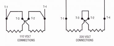
Looks like the motor you have is a split phase dual voltage, without a starting switch. Here is the basic diagram
split%20phase%20motor%20diagram.jpg


And for others you may come across.
https://dl.dropboxusercontent.com/u/13118477/ShopFan/single%20phase%20motor%20connections.pdf

Test your leads for resistance / continuity compare to the diagram and connect per the voltage that you want. If it rotates the wrong way, reverse one winding only with respect to the power connection.

Hope that helps:thumbup:
 

Attachments

  • split phase motor diagram.jpg
    split phase motor diagram.jpg
    61.6 KB · Views: 38

sparky36000

Well-known member
Joined
Dec 25, 2012
Messages
116
Location
North Dakota
Bingo! Very similar to the drawing I was trying to upload. Insert your switch in the T1 lead. Black from source to one side of switch, T1 to second side of switch, white to T4 and your good to go.

Looks like the motor you have is a split phase dual voltage, without a starting switch. Here is the basic diagram
split%20phase%20motor%20diagram.jpg


And for others you may come across.
https://dl.dropboxusercontent.com/u/13118477/ShopFan/single%20phase%20motor%20connections.pdf

Test your leads for resistance / continuity compare to the diagram and connect per the voltage that you want. If it rotates the wrong way, reverse one winding only with respect to the power connection.

Hope that helps:thumbup:
 
To avoid these ads, REGISTER NOW!

MTW

Well-known member
Joined
Aug 6, 2013
Messages
294
Location
SE Michigan
That's not correct. Check the diagram again.
T1 & T2 are the ends of the first winding. T3 & T4 are the second winding. Each winding should read in the very low ohms but not quite 0 ohms. Also test from each winding lead to the frame with all leads isolated there should be no reading (infinite ohms).
Once you figure out which leads belong to winding 1 & 2 label them as in the drawing for your reference.
For 120V operation connect T1 & T3 & 120V Hot ( one wire from winding 1 + one wire from winding 2 + Hot feed)

Repeat for the remaining wires connect T2 & T4 & Neutral ( 2nd wire of winding 1 +2nd wire of winding 2 + neutral.

That should get it running if it's good. To reverse rotation switch one set of winding leads, with respect to the power wires, not both.
 
OP
F

FunkyfullWidth

Well-known member
Joined
Oct 3, 2011
Messages
1,238
Location
Three Rivers, ma
Aaah.... The line drawn in between T1 and T3, also T4 and T2 was messing me up. Now it's perfectly clear. One wire from each winding gets tied together, and then to either neutral or power. so the two wires that I was getting resistance on, one goes to power, the other neutral.
 

Tweeker

Banned
Joined
May 28, 2013
Messages
444
I was able to get my motor working on 110, and able to reverse directions. If I want 220 I see how to do that no problem. My question is based on the second diagram,what wires are switched for reversing direction?
 
Last edited:

MTW

Well-known member
Joined
Aug 6, 2013
Messages
294
Location
SE Michigan
Already included in the original post.

If it rotates the wrong way, reverse one winding only with respect to the power connection.

MTW Ω
 

Tweeker

Banned
Joined
May 28, 2013
Messages
444
Im sorry but what does that mean? Try saying , switch number 2&4 for reverse operation.
Thanks in advance!
 
To avoid these ads, REGISTER NOW!
Top Bottom