To avoid these ads, REGISTER NOW!

Craftsman 115.7575 Pre-block / Mailbox Grinder Restoration

pendragon1998

Well-known member
Joined
Mar 24, 2012
Messages
3,733
Location
NE Georgia
I'm a little hesitant to put this up here for two reasons: 1) because I've never tried as ambitious a restoration as this and 2) I'm ridiculously busy at my job right now and I don't know how quickly I can make progress on this thing.

On the other hand, my job is making me feel like this...

attachment.php


...these days, so maybe a project is exactly what I need.

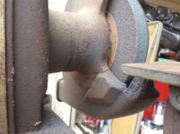
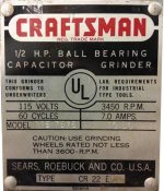
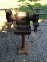
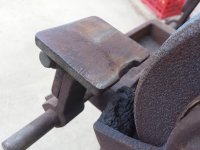
For those who don't follow the block grinder 12 step program thread, I recently bought a pre-block Craftsman grinder model 115.7575 off Craigslist for $60, including the original stand.

attachment.php


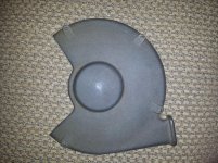
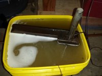
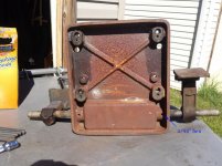
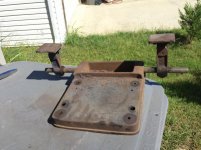
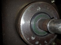
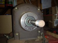
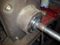
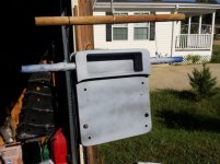
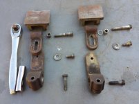
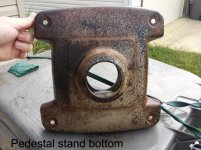
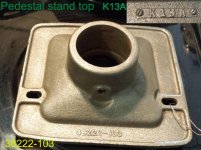
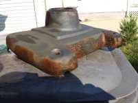
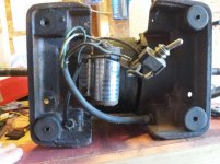
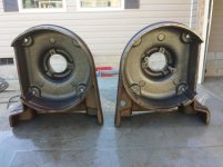
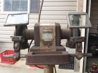
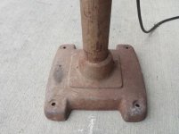
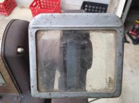
It's heavy, cast-iron, and came with the quenching tray, some beefy tool rests, cracked eye shields, and a grinder in reasonably good, but heavily-used condition. The previous owner was a mechanic outside Memphis. Just for the pedestal stand alone, I'd have been happy at $60.

attachment.php


attachment.php


attachment.php


attachment.php


According to the label (if I interpret it correctly), it was built in Feb. 1958.

attachment.php


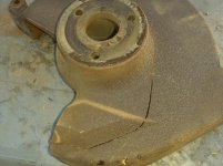
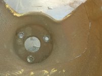
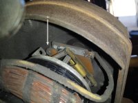
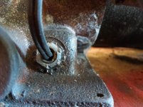
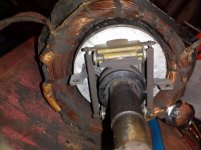
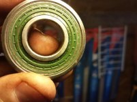
The grinder has some issues, but it's usable as a beater in its current condition (more on the issues coming right up). Still, I'd like to get it fixed up and see if my son and I can't run it for another 56 years.
 

Attachments

  • temper.jpg
    temper.jpg
    34.1 KB · Views: 2,665
  • CL 00I0I_dUnkRTdXfik_600x450.jpg
    CL 00I0I_dUnkRTdXfik_600x450.jpg
    29.1 KB · Views: 2,664
  • 20140918_173930.jpg
    20140918_173930.jpg
    61.9 KB · Views: 3,274
  • 20140918_173938.jpg
    20140918_173938.jpg
    59.4 KB · Views: 2,850
  • 20140918_174015.jpg
    20140918_174015.jpg
    62.3 KB · Views: 2,663
  • 20140918_174315.jpg
    20140918_174315.jpg
    138.2 KB · Views: 2,667
  • 20140918_174435.jpg
    20140918_174435.jpg
    89.6 KB · Views: 3,139
Last edited:
To avoid these ads, REGISTER NOW!
OP
P

pendragon1998

Well-known member
Joined
Mar 24, 2012
Messages
3,733
Location
NE Georgia
(maxed out my pic uploads, continuing here)

So as I said, it's got some problems. It probably needs new bearings (slows to a stop in 1 minute, vs ~3 minutes for my 397.xxxx grinder), but they're not horrible.

The inner wheel guards have some big cracks in them (perhaps it fell over at some point), but the original owner apparently welded them back up. They look pretty bad, but honestly, I don't think they're a big deal at all. For one thing, you can just remove the wheel guards if you want. The manual even suggests it for some accessories. For another, they don't really bear much mechanical strain, so as long as the cracks don't progress (and they're welded), I don't think it will cause me any problems. I plan to use some sort of body filler on the cracks before I paint. Suggestions on that?

attachment.php


attachment.php


attachment.php


attachment.php


So far, I have only taken apart the right side wheel housing, which is where I saw the original owner had welded the inner wheel housing back together. I know cast iron welds are suspect, but as I said, I don't expect this part to see much action, other than vibration or catching an exploding wheel (which I pray never happens). I may even remove it and use this grinder as a buffer, but I'll restore it all before I decide.

attachment.php


attachment.php


attachment.php
 

Attachments

  • 20140918_174302.jpg
    20140918_174302.jpg
    123.4 KB · Views: 2,571
  • 20140918_174204.jpg
    20140918_174204.jpg
    59.6 KB · Views: 2,572
  • 20140918_174115.jpg
    20140918_174115.jpg
    55.4 KB · Views: 2,566
  • 20140918_174252.jpg
    20140918_174252.jpg
    123.7 KB · Views: 2,582
  • 20140918_180948.jpg
    20140918_180948.jpg
    67.4 KB · Views: 2,561
  • 20140918_182413.jpg
    20140918_182413.jpg
    135.5 KB · Views: 2,568
  • 20140918_182438.jpg
    20140918_182438.jpg
    125 KB · Views: 2,569
Last edited:
OP
P

pendragon1998

Well-known member
Joined
Mar 24, 2012
Messages
3,733
Location
NE Georgia
One last photo of the right inner housing crack.
attachment.php


This evening, I made my first, small beginning on the restoration. I cleaned up the right-side outer wheel housing with simple green, then ran it in my electrolysis setup to derust it. It came out very nice and clean. I shot it with a light coat of rustoleum primer tonight to keep it from flash rusting.


Here's the right side outer wheel housing...

BEFORE:
attachment.php


AFTER round 1 of 2 in my electrolysis tank:

attachment.php


attachment.php


In the photo above, it's still got a little rust and gunk I missed on the inner surface. I wire wheeled the gunk off it after this photo was taken, then ran it through the tank again.


Finally, here it is drying after I primed it. I am kind of debating between getting everything primed then painting all at once, or priming and painting each part as I get it ready. It's going to be a while before I have everything cleaned up, so I don't want stuff that I already de-rusted or primed to get re-rusted or dirty before they're painted.

attachment.php


Thanks for looking, that's all for tonight.
 

Attachments

  • 20140920_200439.jpg
    20140920_200439.jpg
    115.1 KB · Views: 2,539
  • 20140920_200402.jpg
    20140920_200402.jpg
    111.2 KB · Views: 2,540
  • 20140918_182444.jpg
    20140918_182444.jpg
    127.7 KB · Views: 2,543
  • 20140920_233111.jpg
    20140920_233111.jpg
    122.2 KB · Views: 2,533
Last edited:

tedsters

Well-known member
Joined
Oct 29, 2012
Messages
1,443
Location
Michigan
are you gonna put the krinkle brown on it with the gold, or haven't you decided on the colors
 

gilbo

Well-known member
Joined
Feb 1, 2010
Messages
716
for me i generally derust a piece and then prime it after CLEAN and DRY, then continue with the rest of the pieces. after all pieces primed then i paint all at once.

after a piece is primed it shouldnt rust, unless the piece wasnt totally dry before priming
 
Last edited:

Strouty

Well-known member
Joined
Mar 21, 2010
Messages
38,209
Location
Southern Maine
I was always under the impression that you need to drill a hole at the end of the crack to actually stop it.

Pendragon1998 it is looking good, keep posting progress.
 
OP
P

pendragon1998

Well-known member
Joined
Mar 24, 2012
Messages
3,733
Location
NE Georgia
I was always under the impression that you need to drill a hole at the end of the crack to actually stop it.

Pendragon1998 it is looking good, keep posting progress.

Thanks - judging from the rust inside the crack and the age of the weld, I think it's fairly stable. If I had to repair it from scratch, I'd consider drilling a hole, but I think I'll just pack the unwelded portion of the crack with something (perhaps braze it as someone suggested), and call it good.
 

hemifalcon

Well-known member
Joined
Jan 4, 2013
Messages
708
Location
Union Grove, Wisconsin
Those cracks are welded on the inside on both sides?? Then I'd call them good. "body filler"--umm no.. Use some JB weld if you're insistent on restoring the monster cast iron ears on this old girl or brazing as noted previously. Like you mentioned--this grinder saw some heavy use apparently and now she'll probably live a nice easy retirement in your paws. I just sold mine on the auction site to a cool fella who's also a member on here.. You got a pretty good deal especially with what people are paying for those pedestals. Nice find--I"ll follow along.
 
OP
P

pendragon1998

Well-known member
Joined
Mar 24, 2012
Messages
3,733
Location
NE Georgia
I really like the stand. Looks sturdy

Definitely heavy. I can lift it, but after my back surgery last year, I really shouldn't be dragging it around. I got it up on top of my floor jack and wheeled it outside for those pics, earlier - lol.

Those cracks are welded on the inside on both sides?? Then I'd call them good. "body filler"--umm no.. Use some JB weld if you're insistent on restoring the monster cast iron ears on this old girl or brazing as noted previously.

The cracks on the right hand side are welded on the inside. The one on the right side wheel housing was NOT welded, as I discovered today when I removed the housing. That's disappointing. It's actually the worst of the cracks. I'm going to have to evaluate what to do with it, as I don't have a welder. I have a stepbrother-in-law who is a professional welder. I might mail the part to him to weld if I can flat-rate it.


Yeah, so today I removed the grinder from the base and started cleaning up the base. It was pretty rusted up and there was some sort of solid mud/rust **** in the reservoir that I had to chip out with a prybar and a mallet. What a lark.

attachment.php


attachment.php


The underside of the base apparently collected moisture, probably from the water used in the reservoir. This looked like rust from standing water, to me anyway. The tool rest posts are connnected to the base with two 5/32" hex studs, but even when I removed them, I had trouble removing the posts. I didn't want to risk cracking the base by whaling on it, so I'm leaving them in, at least until it's been through the electrolysis tank.

attachment.php


I wire-brushed the worst of the rust off to save time in the tank later. Ignore the baking soda box; I was mixing up electrolytic solution (washing soda works too, but I had baking soda handy).

attachment.php


I didn't have a tank big enough for the whole part, but I got the cast iron part of the base mostly submerged, anyway. I'll flip vertically later, then front-to-back to hit the rear. The anode is a big chunk of RR plate. Now, if I was going to leave the part unpainted, I wouldn't leave it partly out of the water, because I suspect that will give me a dark line that won't be removable; but, since I'm going to paint it, I don't care. Both ends of the tool rest posts are going to be (at minimum) submerged fully and later sanded, so they'll be ok too.

Below, you can see my handy-dandy electrolysis power supply, which I modified from an ATX computer power supply. It even has fancy LEDs on the cooling fan. Please ignore my messy floor. I was in the middle of cleaning. . . yeah.

attachment.php


The bubbles you see are a mixture of simple green residue and hydrogen/oxygen bubbles from the electrolysis.

attachment.php
 

Attachments

  • 20140922_152650.jpg
    20140922_152650.jpg
    128.5 KB · Views: 2,316
  • 20140922_152542.jpg
    20140922_152542.jpg
    75.1 KB · Views: 2,318
  • 20140922_144831.jpg
    20140922_144831.jpg
    62.1 KB · Views: 2,317
  • 20140922_143358.jpg
    20140922_143358.jpg
    70.7 KB · Views: 2,323
  • 20140922_143332.jpg
    20140922_143332.jpg
    69.4 KB · Views: 2,323
  • 20140922_143225.jpg
    20140922_143225.jpg
    72.5 KB · Views: 2,328
Last edited:
OP
P

pendragon1998

Well-known member
Joined
Mar 24, 2012
Messages
3,733
Location
NE Georgia
Taking a look at the right inner wheel housing under better light, I'm feeling worse about its prospects. Do you think this part is salvageable by welding it?

I still need to send these photos to my BIL. I don't interact with them often, so I don't know him well, but he's supposed to be a very good welder.

attachment.php


attachment.php


attachment.php


attachment.php


attachment.php
 

Attachments

  • 20140922_172447.jpg
    20140922_172447.jpg
    70.5 KB · Views: 2,903
  • 20140922_172439.jpg
    20140922_172439.jpg
    69.1 KB · Views: 2,901
  • 20140922_172351.jpg
    20140922_172351.jpg
    64.6 KB · Views: 2,900
  • 20140922_172338a.jpg
    20140922_172338a.jpg
    54.5 KB · Views: 2,900
  • 20140922_172338.jpg
    20140922_172338.jpg
    56.6 KB · Views: 2,905
OP
P

pendragon1998

Well-known member
Joined
Mar 24, 2012
Messages
3,733
Location
NE Georgia
With the wheels removed, there's some side to side play in the arbor shaft. I can push the bearing almost all the way out of the housing. Is this a problem, or is it normal? If I recall correctly from what I've read, the bearing should be non-moving on the shaft, but can be fairly loose in the housing. Is that much looseness ok?

attachment.php


attachment.php


attachment.php


attachment.php


I found a list of replacement bearings for old Craftsman grinders at:
Replacement Bearing List - Sears Craftsman/Companion/Dunlap Machinery

Craftsman 115.7575
* Original Bearings: ND (USA) 97503 (seal and retention shield)
* Accurate replacement: 6203
 

Attachments

  • 20140922_172250.jpg
    20140922_172250.jpg
    60.7 KB · Views: 2,273
  • 20140922_172242.jpg
    20140922_172242.jpg
    144.4 KB · Views: 2,266
  • 20140922_172231.jpg
    20140922_172231.jpg
    60.1 KB · Views: 2,269
  • 20140922_172222.jpg
    20140922_172222.jpg
    58 KB · Views: 2,264

rickhigginshtbr

Well-known member
Joined
Aug 7, 2012
Messages
1,551
Location
Lower Bucks, PA
eh... that crack... carefully try to use a clamp and see if you can even clamp it back into shape. If it doesn't come close, I don't know... But, if he doesn't want to weld it, JB Weld works great on cast parts.
 

jakemac

Well-known member
Joined
May 21, 2013
Messages
9,035
Location
New England
The area on that housing that sees the most stress seems to be ok, so I wouldn't worry about welding or brazing it. The only issue you may have is making sure it doesn't warp during the welding process.

Can't help on the bearing/arbor issue though.
 
To avoid these ads, REGISTER NOW!

Mr. Brooks

Well-known member
Joined
Dec 11, 2012
Messages
311
I would imagine the side to side play in the shaft is eliminated when the gaurds are put back on. It's seems they may hold the bearings in place, unless there was another cap that was between the guard and end bell. New bearings is always recommended, 6203 should be correct. Same as my baldor 1/2 horse.
 

gilbo

Well-known member
Joined
Feb 1, 2010
Messages
716
as far as the tool rest shaft goes,after removing set screws, i sprayed PB blaster in the holes, i then clamped the base on the vise, then wrapped a towel around the tool shaft rest, then used a pair of vise grip and twisted it out
 
Last edited:

torqueman2002

Well-known member
Joined
Jun 3, 2009
Messages
6,138
Location
SE Michigan
... there's some side to side play in the arbor shaft. I can push the bearing almost all the way out of the housing. Is this a problem, or is it normal? If I recall correctly from what I've read, the bearing should be non-moving on the shaft, but can be fairly loose in the housing. Is that much looseness ok?
The CM grinders that I've worked on (~11), have had the bearings stay with the arbor and also, stay in the housing during dis-assembly. All have needed gentle persuading. None had a loose fit in the housing, the design is for an interference fit.

Consider using: LOCTITE Bearing Mount, or similar.
http://www.amazon.com/s/ref=nb_sb_ss_i_0_15?url=search-alias%3Daps&field-keywords=loctite%20bearing%20mount&sprefix=LOCTITE+bearing%2Caps%2C224

You may also find the following threads helpful.
"let's see your craftsman block grinders" http://tinyurl.com/let-s-see-CM-block-grinders
Edit - Ooops, I see you have already visited and posted. Never mind. :eek:
http://tinyurl.com/CM-Block-Grinders-Why-the-Fuss
 
Last edited:
OP
P

pendragon1998

Well-known member
Joined
Mar 24, 2012
Messages
3,733
Location
NE Georgia
Cleaned and primed the quench tray base the other day. Never could get the rods for the rests out, so I just taped them and used them as a handy hanger instead. Here's the base halfway through priming. I used Rustoleum Pro gray primer. I also hit the other outer wheel guard with primer. No pics on that one.

attachment.php


attachment.php


I'm continuing to think about the color scheme. I want to keep it close to original. The pedestal was originally golden, although most of the paint is gone and it will need to be sanded to bare metal and repainted.

Here is an area of protected paint on my pedestal. I tried to get a 'paint swatch' in photoshop.

attachment.php


Here's someone else's pedestal in the same color. I found this in one of the other block grinder threads.

attachment.php


And the same color on a drill press from the google.

attachment.php


I'm not totally sold on the pedestal being all gold-colored. I was thinking about brown or a dark bronze on the base and top plate. Here's a photoshopped version of what I'm thinking about. This is someone else's photo that I manipulated a little. I think the brown is too brown; I would like to get it a little more bronzy than brown. I'd probably remove the equipment plate and paint the center bezel gold to match the pedestal.

attachment.php


If I paint the quench tray base dark bronze, I was thinking I'd probably mask off the inside of the quench reservoir and paint it golden, so that if a little screw or part fell in there, it would be more visible.
 

Attachments

  • 15121-C.jpg
    15121-C.jpg
    33.9 KB · Views: 1,163
  • Color-scheme---proposed.jpg
    Color-scheme---proposed.jpg
    34.8 KB · Views: 1,165
  • 7047-A.JPG
    7047-A.JPG
    25 KB · Views: 1,164
  • 20140926_131952.jpg
    20140926_131952.jpg
    52.3 KB · Views: 1,957
  • 20140923_160542.jpg
    20140923_160542.jpg
    66.6 KB · Views: 1,171
  • 20140923_160520.jpg
    20140923_160520.jpg
    65 KB · Views: 1,166
OP
P

pendragon1998

Well-known member
Joined
Mar 24, 2012
Messages
3,733
Location
NE Georgia
I don't have a lot to report from this week, but I got my pedestal top and bottom cleaned up and primed, and I de-rusted (mostly) the grinder rests. One of them still needs to be wire brushed to get some caked on **** off, but they'll be ready for priming shortly.

I thought I'd include a number of photos showing the cast-in numbers from the parts I was working on for reference, in case anyone was doing research.


The top part of the pedestal stand (upside down), as I'm drying it over very low heat on my stove after scrubbing off the oxides produced by electrolysis. The little plate with the screws is actually the impression from the casting mold (i.e., there are not any real screws in the part; it's just the impression from the screw heads).

attachment.php


Bottom part of the pedestal stand after electrolysis. The rust and old paint still attached was loosened up significantly. It wire brushed off very easily.

attachment.php


attachment.php


Partway through wirebrushing off the rust and old paint from bottom of pedestal stand. ****** thing was already flash rusting in the hot sun. I ended up doing a quick rub with a scotch brite pad to get most of the flash rust off, then just primed over it. I'm sure the original paint job was done over some flash rust back in 1958. I think the primer said it was ok to paint over a little rust that wasn't flaking. No way to avoid it that I'm aware of, short of oiling or waxing immediately as you expose the bare metal, but then your paint wouldn't adhere, of course.

attachment.php


The disassembled tool rests, prior to electolysis. I was missing a washer on one, probably because the previous owner lost it (it was easy to drop it unnoticed).

attachment.php


Cast-in numbers for tool rest components. The left and right rests were the same parts (there is no difference between them).

attachment.php


All for now....
 

Attachments

  • 20141002_202801.jpg
    20141002_202801.jpg
    66.3 KB · Views: 1,132
  • 20141001_163409.jpg
    20141001_163409.jpg
    51.3 KB · Views: 1,132
  • 20140928_082237.jpg
    20140928_082237.jpg
    79.5 KB · Views: 1,392
  • 20140928_082213.jpg
    20140928_082213.jpg
    90.3 KB · Views: 1,148
  • 20140927_145909.jpg
    20140927_145909.jpg
    78.5 KB · Views: 1,133
  • 20141001_153224.jpg
    20141001_153224.jpg
    54.7 KB · Views: 1,135
Last edited:
OP
P

pendragon1998

Well-known member
Joined
Mar 24, 2012
Messages
3,733
Location
NE Georgia
It's been about the strangest week I've experienced in a long, long time. However, I did find an hour to get out in the garage and tinker around on the grinder.

My current task is to strip the pedestal post bare for painting. The outer surface contains a lot of rust and old paint that needed to go, and the interior has more rust. I built a wooden cradle to hold the post and attached a oil filter socket to the end (with duct tape, what could go wrong?!). The bottom part of the cradles have V-notches cut out to reduce friction and are screwed directly into my bench top. The upper parts are just squared off to keep the pipe from flying loose; they're screwed into the lower supports.

attachment.php


I then could spin the entire pipe in the cradle (FAST) using my drill, without it popping loose.

attachment.php


Put a small stop block at the non-drill end, so the drill wouldn't push the end too far through the cradle.

attachment.php


By holding a piece of 100 grit sandpaper up against it with a pad so my hand wouldn't burn, I was quickly able to get it to bare metal. It actually spins fairly smoothly, all things considered.

attachment.php


I also came up with a plan to de-rust the inside. I'm going to pour in about 3 or 4 cups of coarse sand and cap the other end, then just spin it to abrade off the rust inside. Don't know if it will work, but its not the end of the world if the paint job inside of the post isn't perfect. My other idea was to suspend the pedestal pipe inside a capped pvc pipe, fill it with electrolyte, run a section of rebar down inside the center of the pedestal section, and hook it up to the electrolysis power source. That would work too, as long as the rebar didn't touch. But it wouldn't involve a Spinning Contraption of Death, so not as much fun.
 

Attachments

  • 20141007_164507.jpg
    20141007_164507.jpg
    62.9 KB · Views: 1,115
  • 20141007_164355.jpg
    20141007_164355.jpg
    64.5 KB · Views: 1,116
  • 20141007_164028.jpg
    20141007_164028.jpg
    72.8 KB · Views: 1,109
  • 20141007_164341(0).jpg
    20141007_164341(0).jpg
    78.4 KB · Views: 1,402
Last edited:

gilbo

Well-known member
Joined
Feb 1, 2010
Messages
716
nicely done so far, i just have the lamp, grinder stand to finish up on my grinder
 
OP
P

pendragon1998

Well-known member
Joined
Mar 24, 2012
Messages
3,733
Location
NE Georgia
I hope you guys don't think I'm going overboard with the documentation

Well, the 'sand in the pipe' idea didn't pan out; the pipe wasn't balanced well enough and it started to shake too hard. In theory, I still think it would have been a cool approach. Oh well, it's never good to get sand in your pipe, I guess. lol

I didn't feel like buying any additional electrolysis supplies, so I ended up attaching a wire brush on a long rod and using my drill to try and remove the loose rust inside the pedestal pipe. It worked ok, and since I at least got the loose stuff out, I called it good and primed the pipe. I used an etching primer to hopefully adhere to the smooth surface better, and scuffed it up with 100 grit sandpaper prior to priming.

What I started with. Not a lot of pics because I was short on time:
attachment.php


After finishing brushing one half. You're looking down the pipe from the un-brushed end; hopefully you can see where the rusty part transitions into the smooth, brushed portion.

attachment.php


I also cleaned up the other cracked inner wheel guard plate. This one is the one that the previous owner welded up (the other one was also cracked but was unwelded). UI haven't primed the inner wheel guards yet, because I'm thinking about how best to attak those cracks. Cracks are whack.

attachment.php


The internal wheel housing is marked with number 5218706 and 'B-over-T' 1N
attachment.php


attachment.php


attachment.php


attachment.php
 

Attachments

  • 20141012_145928.jpg
    20141012_145928.jpg
    93.2 KB · Views: 1,702
  • 20141012_145919.jpg
    20141012_145919.jpg
    87.3 KB · Views: 1,702
  • 20141012_145943.jpg
    20141012_145943.jpg
    62.4 KB · Views: 1,714
  • 20141012_145857.jpg
    20141012_145857.jpg
    85.5 KB · Views: 1,088
  • 20141012_145844.jpg
    20141012_145844.jpg
    69.1 KB · Views: 1,708
  • 20141011_183314.jpg
    20141011_183314.jpg
    116.8 KB · Views: 1,089
  • 20141011_174556.jpg
    20141011_174556.jpg
    140.8 KB · Views: 1,093
Last edited:

404

Well-known member
Joined
Aug 23, 2014
Messages
3,463
Location
Mass
A crack in a material causes a stress concentration that increases as 1 over the radius of the crack tip.. So as the crack gets very sharp (radius goes to zero) the stress concentration goes to infinity.. In ductile materials (soft steel, copper, lead) the tip of the crack blunts as the material is deformed and flows. In a brittle material like cast iron or glass there is not much flow so the crack stays sharp.

A round hole has a stress concentration of 2.

Drilling the hole is not so much to stabilize the crack as to reduce the chance of it running to complete breakage if the wheel explodes and hits the guard.

As an aside, in some applications the initial crack in the material might be internal due to inclusions or slag inside a forged part. In the worst case a internal flaw too small to detect with testing can grow quickly to part failure, as in the link.
http://www.ndt.net/apcndt2001/papers/912/912.htm

Regards,
404
 
OP
P

pendragon1998

Well-known member
Joined
Mar 24, 2012
Messages
3,733
Location
NE Georgia
I finally pushed past a difficult period at work, so I'm taking a three day weekend to regain some sanity. I finally separated the two halves of my grinder today in order to see what I was dealing with.

attachment.php


Someone was in here before me (see the damaged fastener?).

attachment.php


To separate them, you remove four end-threaded rods with nuts and gently pry or tap the left side loose first.

By the way, I'll refer to the left and right sides as you would see them if the grinder was facing you (so the power cord goes in the right side and the lamp comes out of the left).

Anyway, the left side came off easily, and I was able to pull the bearing off the shaft with firm hand pressure once I gave it a little squirt of penetrating oil (WD-40 was what I had on hand). Remember to remove the retaining rings with a pair of snap ring pliers.

attachment.php


attachment.php


The right side gave me a lot more trouble, mainly because I was trying to be gentle, so as not to break anything. You need to disconnect two wires going to the centrifugal switch. One wire comes off the capacitor, and one comes out of the windings. My wires were soldered on (joy), so I resorted to using a small flathead screwdriver to remove the two screws holding the switch board onto the right side housing. The board would probably crack easily, so be careful if you do that. You can unscrew them if you're patient and have a small enough driver.

Screw #1 of 2
attachment.php


Screw #2 of 2
attachment.php

At that point, the ****** bearing would not give up the ghost and release the housing, so I spent an hour coaxing it loose. I finally resorted to damaging the bearing since I was planning to replace them anyway; it was really stuck in the housing.

Housings removed and in the process of being cleaned and de-rusted.
attachment.php
 

Attachments

  • 20141017_155306.jpg
    20141017_155306.jpg
    124.8 KB · Views: 1,069
  • 20141017_154520.jpg
    20141017_154520.jpg
    145.8 KB · Views: 1,063
  • 20141017_160159.jpg
    20141017_160159.jpg
    91.2 KB · Views: 1,066
  • 20141017_160135.jpg
    20141017_160135.jpg
    137.5 KB · Views: 1,068
  • 20141017_151740.jpg
    20141017_151740.jpg
    74.3 KB · Views: 1,062
  • 20141017_151730.jpg
    20141017_151730.jpg
    64.7 KB · Views: 1,284
  • 20141017_164616.jpg
    20141017_164616.jpg
    59.4 KB · Views: 1,055
OP
P

pendragon1998

Well-known member
Joined
Mar 24, 2012
Messages
3,733
Location
NE Georgia
(in progress)

Inside of housings
attachment.php


Yeah, this is being replaced. Dangerous power cord.

attachment.php


Start capacitor switch

attachment.php


Centrifugal weight assembly

attachment.php


attachment.php


Capacitor. I want to smack whomever did this hack wiring job.
I think I'm going to have to replace the motor start capacitor.

attachment.php


attachment.php
 

Attachments

  • 20141017_164723.jpg
    20141017_164723.jpg
    59.8 KB · Views: 1,054
  • 20141017_163641.jpg
    20141017_163641.jpg
    56.4 KB · Views: 1,055
  • 20141017_174825.jpg
    20141017_174825.jpg
    138.6 KB · Views: 1,081
  • 20141017_165949.jpg
    20141017_165949.jpg
    68.7 KB · Views: 1,055
  • 20141017_165911.jpg
    20141017_165911.jpg
    66.4 KB · Views: 1,056
  • 20141017_165843.jpg
    20141017_165843.jpg
    77.7 KB · Views: 1,890
  • 20141017_174816.jpg
    20141017_174816.jpg
    112.8 KB · Views: 1,282
Last edited:
OP
P

pendragon1998

Well-known member
Joined
Mar 24, 2012
Messages
3,733
Location
NE Georgia
Just a few more pics. Here is an original bearing. I measure it at 40 mm OD, 17 mm ID, and 12 mm thick, which agrees with what I've read elsewhere.

One face reads: 'ND ... 3203 ... MADE IN USA'

attachment.php


The other face reads: 'NEW DEPARTURE ... Z503 SENTRI-SEAL ... MADE IN USA'
attachment.php


I think I'm probably going to replace the bearings with Japanese 6203-2NSE Nachi Bearing 17x40x12 Sealed C3 Ball Bearings from Amazon. Is there anything better for this application?

attachment.php
 

Attachments

  • 20141017_170519.jpg
    20141017_170519.jpg
    75 KB · Views: 1,064
  • 20141017_170919.jpg
    20141017_170919.jpg
    55.8 KB · Views: 1,068
  • hv00xenj.jpg
    hv00xenj.jpg
    90.6 KB · Views: 1,068
Last edited:
OP
P

pendragon1998

Well-known member
Joined
Mar 24, 2012
Messages
3,733
Location
NE Georgia
I took a closer look at the motor start capacitor. It was wrapped in a cardboard roll, with no identifying markings, so I took a chance and tore open the roll.

attachment.php


attachment.php


attachment.php


Luckily for me, I revealed just what I wanted to see: the maker, the operating microfarad rating, and the operating voltage.

The motor start capacitor for the Craftsman 115.7575 bench grinder was made by Mallory and was rated at 70 MFD and 125 VAC.

I believe that this is a non-polarized aluminum electrolytic capacitor (I didn't see any markings indicating + or -, and what I've read suggests these aren't normally polarized).

attachment.php


I ordered a BMI 72-86 MFD 110 / 125 VAC motor start capacitor. BMI (Barker Microfarads) builds these things in the USA, which is nice. I didn't want to stick a Chinese capacitor in my vintage USA machine. Just wouldn't seem right.


EDITED TO ADD (11/6/14): I originally ordered this from Airstar Solutions, but after a week or two of hearing nothing, I contacted them and found out it was out of stock and not expected to be restocked (they promptly issued a refund at that point). I later ordered a Mallory branded (USA manufactured) 72-88 MFD 110-125V capacitor on ebay. I hadn't seen Mallory caps available when I initially searched, but that's pretty cool, replacing it with an OEM capacitor. It was cheaper on ebay too.

If anyone sees a reason this isn't the correct replacement part, please speak up! I'm 95% certain this is correct, but I could definitely be wrong.

attachment.php
 

Attachments

  • 20141017_174747.jpg
    20141017_174747.jpg
    59.4 KB · Views: 1,049
  • 20141018_185513.jpg
    20141018_185513.jpg
    144.4 KB · Views: 1,469
  • StartCapacitor.jpg
    StartCapacitor.jpg
    8.8 KB · Views: 1,049
Last edited:

torqueman2002

Well-known member
Joined
Jun 3, 2009
Messages
6,138
Location
SE Michigan
I took a closer look at the motor start capacitor. It was wrapped in a cardboard roll, with no identifying markings, so I took a chance and tore open the roll.

Luckily for me, I revealed just what I wanted to see: the maker, the operating microfarad rating, and the operating voltage.

The motor start capacitor for the Craftsman 115.7575 bench grinder was made by Mallory and was rated at 70 MFD and 125 VAC.

I believe that this is a non-polarized aluminum electrolytic capacitor (I didn't see any markings indicating + or -, and what I've read suggests these aren't normally polarized).

I ordered a BMI 72-86 MFD 110 / 125 VAC motor start capacitor. BMI (Barker Microfarads) builds these things in the USA, which is nice. I didn't want to stick a Chinese capacitor in my vintage USA machine. Just wouldn't seem right.

If anyone sees a reason this isn't the correct replacement part, please speak up! I'm 95% certain this is correct, but I could definitely be wrong.
That will work, very similar to what I have used.:thumbup:
 
OP
P

pendragon1998

Well-known member
Joined
Mar 24, 2012
Messages
3,733
Location
NE Georgia
Your grinder looks like it is in great shape! Thanks for sharing, I like seeing these old pre-blocks. I am really having a good time sharing my restoration and I enjoy reading everyone's comments.
 
OP
P

pendragon1998

Well-known member
Joined
Mar 24, 2012
Messages
3,733
Location
NE Georgia
Sorry if I seem to have dropped off the face of the earth. I've been working on various projects, but I'm continuing to make progress on my grinder. I hit the pedestal with some X-O Rust bronze paint and I think it looks pretty good. Pics will have to wait on that until I have a few minutes. In the meantime, here is my work on reproducing the label.

My original label is shot to heck, plus I managed to mangle one hole when I removed the rivets to clean up the center bezel.

attachment.php


For comparison, here is a more intact label for the same model that I found on the interwebs (perhaps here; sorry, I'm not sure who to credit - I was just searching for block grinder pics and saved it).

attachment.php


And finally, here is my photoshopped mockup of a replacement label. The original plates for these were originally printed (probably screen printed) on a thin sheet of aluminum and then the model number and date were stamped in. My plan, once I get it just 'right', is to have it printed on a license plate aluminum blank and cut it out. I'm pretty sure there are sellers on ebay who will let you send them a photo (e.g., of your pet) and they'll print it on an aluminum vanity plate. I'll create an image file containing a few of these labels, send it to be printed, then cut them out of the resulting aluminum plate.

I have it sized at >300 dpi on my PC, and I'll print the white as clear in the final version, so it will be metal 'colored' where it's white. Orange indicates drilling points (got the diameter off a scan of my original).

attachment.php


I'm not 100% happy with the font. I used Arial narrow and stretched it in some places, but the original font, while similar to Arial narrow, has greater spacing between letters and thinner letter bodies. Anyone know a downloadable match?

Thoughts?
 

Attachments

  • someone's-label.jpg
    someone's-label.jpg
    97.8 KB · Views: 979
  • newlabel4A.jpg
    newlabel4A.jpg
    75.5 KB · Views: 977
Last edited:

nine4gmc

Well-known member
Joined
Mar 24, 2012
Messages
14,357
Location
Dallas
I spent literally days on "azfonts.net" searching for fonts for a sign I made. A lot of them are free download, you just have to look through thousands of fonts to find what you are after. Great job on the label. :beer:
 
To avoid these ads, REGISTER NOW!
Top Bottom