After rebuilding two Champion R15B pumps over the past two years I felt it was time to share what I learned, in the hope that I can save others some time and effort.
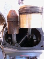
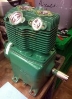
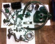
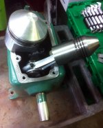
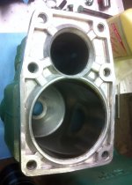
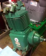
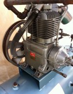
Basics: The Champion R15B pump is a two-cylinder, two-stage, splash lubricated design, utilizing a cast iron crankcase and a cast aluminum integral cylinder and head assembly, with non-replaceable steel liners. Design power range is 3-5 hp, with a nominal air delivery at 175 psi of 9.7 cfm at 440 rpm (3hp) and 16.5 cfm at 710 rpm. The crankshaft is cast iron, supported by tapered roller bearings. Rods are aluminum, with replaceable needle bearings on the small ends. There are no big-end bearings. Oil slingers are provided in the form of steel roll pins pressed into the bottom of the rods. The first stage has a 4 5/8” bore and uses an aluminum piston. Second stage bore is 2 ½”, with a steel piston. Both pistons use three compression rings and one oil control ring. The valves are stainless steel disc assemblies, which can be easily replaced by removing the inlet/outlet fittings. They can also be disassembled for cleaning. A centrifugal unloader is provided to relieve pressure from the high pressure cylinder on startup. Flyweights bolted to the crankshaft will extend once the pump is on speed, withdrawing a pin in the valve assembly, allowing a ball to move to the closed position, blocking the flow air from the unloader tube to the vent fitting. An oil breather tube is also provided to vent oil vapors in the unloader housing to the inlet fitting. Some pumps for HVAC applications may be fitted with head unloaders in the outlet fittings, which will open both first and second stage exhaust valves using external pilot pressure, to reduce discharge pressure. A pressure-lubricated version is also available, which uses different unloader housing, incorporating an oil pump driven off the end of the crankshaft.
Misc Info:
-The military used a version of this pump and the manual for that (with specs, drawings, and nominal dimensions) is available online. Search for TM 5-4310-350-14
-Overhaul/parts kits sold on eBay and elsewhere all seem to be made by the same (overseas) supplier. Quality seems pretty close to OE. I get my parts here: http://www.compressorpartsstore.com/R15-p/tuneup-r15b.htm
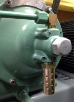
-The bottom of the unloader cover has a threaded discharge port (directly below the valve) which may or may not have a plastic restrictor plug or a felt ‘filter’. I recommend installing a small ½ npt air muffler (McMaster 9835K43). This quiets the thing down quite a bit when the unloader opens as the pump kicks off.
-The compressor outlet/discharge fitting uses an unusual thread, 1”-18. This is sized for a ¾ tube flare nut. If you want to use something different (such as a stainless flex hose as I do), you’ll need a ¾ tube compression fitting (McMaster 5220K84). Remove and discard the compression nut, and thread that end into the compressor outlet. The other end is ¾ npt.
Basics: The Champion R15B pump is a two-cylinder, two-stage, splash lubricated design, utilizing a cast iron crankcase and a cast aluminum integral cylinder and head assembly, with non-replaceable steel liners. Design power range is 3-5 hp, with a nominal air delivery at 175 psi of 9.7 cfm at 440 rpm (3hp) and 16.5 cfm at 710 rpm. The crankshaft is cast iron, supported by tapered roller bearings. Rods are aluminum, with replaceable needle bearings on the small ends. There are no big-end bearings. Oil slingers are provided in the form of steel roll pins pressed into the bottom of the rods. The first stage has a 4 5/8” bore and uses an aluminum piston. Second stage bore is 2 ½”, with a steel piston. Both pistons use three compression rings and one oil control ring. The valves are stainless steel disc assemblies, which can be easily replaced by removing the inlet/outlet fittings. They can also be disassembled for cleaning. A centrifugal unloader is provided to relieve pressure from the high pressure cylinder on startup. Flyweights bolted to the crankshaft will extend once the pump is on speed, withdrawing a pin in the valve assembly, allowing a ball to move to the closed position, blocking the flow air from the unloader tube to the vent fitting. An oil breather tube is also provided to vent oil vapors in the unloader housing to the inlet fitting. Some pumps for HVAC applications may be fitted with head unloaders in the outlet fittings, which will open both first and second stage exhaust valves using external pilot pressure, to reduce discharge pressure. A pressure-lubricated version is also available, which uses different unloader housing, incorporating an oil pump driven off the end of the crankshaft.
Misc Info:
-The military used a version of this pump and the manual for that (with specs, drawings, and nominal dimensions) is available online. Search for TM 5-4310-350-14
-Overhaul/parts kits sold on eBay and elsewhere all seem to be made by the same (overseas) supplier. Quality seems pretty close to OE. I get my parts here: http://www.compressorpartsstore.com/R15-p/tuneup-r15b.htm
-The bottom of the unloader cover has a threaded discharge port (directly below the valve) which may or may not have a plastic restrictor plug or a felt ‘filter’. I recommend installing a small ½ npt air muffler (McMaster 9835K43). This quiets the thing down quite a bit when the unloader opens as the pump kicks off.
-The compressor outlet/discharge fitting uses an unusual thread, 1”-18. This is sized for a ¾ tube flare nut. If you want to use something different (such as a stainless flex hose as I do), you’ll need a ¾ tube compression fitting (McMaster 5220K84). Remove and discard the compression nut, and thread that end into the compressor outlet. The other end is ¾ npt.
Attachments
Last edited: