StevenMorgan
Well-known member
I've been doing a lot of research on this subject trying to sort through the posts on various threads and deciphering the info. Regardless whether you have a 5hp, 7.5hp or 10hp compressor, these are the rules for a good and legal installation. Here is my breakdown to confirm my thoughts and to put all the info out there yet again for others to hopefully comment on, correct me about, and benefit from.
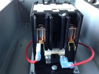
1. If your compressor has a motor that is a no kidding 3hp or more, you'll likely need a magnetic motor starter to switch the thing off and on, instead of wiring directly through a pressure switch. Most pressure switches are only good for about 3hp. Also, the big compressors become much easier to hardwire than to buy plugs and receptacles any bigger NEMA 50a style plugs capable of handling this horsepower... There are plenty of threads on this topic.
2. When selecting a motor starter, choose the correct starter based on the HP rating, phase, and amp rating listed on the motor starter specs and verify it meets the full load amps (FLC or FLA) provided on the nameplate of the motor. It is possible to use a 3 phase (3 pole) starter on a single phase (2 pole) starter, just ensure it meets the specs of your motor.
3. When selecting power wires from the panel to the motor starter, use the correct NEC table to define an amperage... NEC table 430.248 is for single phase AC motors and NEC 430.250 is for three phase AC motors. Use the right chart. Multiply that amperage by 125% to get the amps your wire needs to carry at your motor's voltage.
4. To size the circuit breaker, Use the FLA or FLC amperage from the appropriate NEC table and multiply by 250% to find the maximum circuit breaker size usable to account for the massive inrush current these motors need for startup.
Wire for motor circuits is sized differently than standard branch circuits. Breakers can be rated higher than the wire ampacity because the breaker for a motor circuit only protects against short circuits and ground faults but not overloads. Overloads are handled by either the overload relays in the motor starter or the overload on the motor itself(red push button).A smaller breaker is often used, but the exact size depends on many variables.
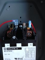
5. Motor starters have several different voltages for the coil, with 120v and 240v being most common. Wiring your motor starter gets pretty specific at this point, depending on your choices of motor starter manufacturer, pressure switch, an on/off switch, and if you need service disconnects for your location. (anything further than 50' from the service panel, or not in line of sight of the panel.)
6. Once you add a motor starter to your compressor wiring setup, the power to the motor is controlled by the magnetic motor starter, and subcomponents like a pressure switch or a manual on/off switch are part of the control circuit and don't have a large amperage flow through them. Selecting a smaller 12awg or 14awg wire for these control wires.
1. If your compressor has a motor that is a no kidding 3hp or more, you'll likely need a magnetic motor starter to switch the thing off and on, instead of wiring directly through a pressure switch. Most pressure switches are only good for about 3hp. Also, the big compressors become much easier to hardwire than to buy plugs and receptacles any bigger NEMA 50a style plugs capable of handling this horsepower... There are plenty of threads on this topic.
2. When selecting a motor starter, choose the correct starter based on the HP rating, phase, and amp rating listed on the motor starter specs and verify it meets the full load amps (FLC or FLA) provided on the nameplate of the motor. It is possible to use a 3 phase (3 pole) starter on a single phase (2 pole) starter, just ensure it meets the specs of your motor.
3. When selecting power wires from the panel to the motor starter, use the correct NEC table to define an amperage... NEC table 430.248 is for single phase AC motors and NEC 430.250 is for three phase AC motors. Use the right chart. Multiply that amperage by 125% to get the amps your wire needs to carry at your motor's voltage.
4. To size the circuit breaker, Use the FLA or FLC amperage from the appropriate NEC table and multiply by 250% to find the maximum circuit breaker size usable to account for the massive inrush current these motors need for startup.
Wire for motor circuits is sized differently than standard branch circuits. Breakers can be rated higher than the wire ampacity because the breaker for a motor circuit only protects against short circuits and ground faults but not overloads. Overloads are handled by either the overload relays in the motor starter or the overload on the motor itself(red push button).A smaller breaker is often used, but the exact size depends on many variables.
5. Motor starters have several different voltages for the coil, with 120v and 240v being most common. Wiring your motor starter gets pretty specific at this point, depending on your choices of motor starter manufacturer, pressure switch, an on/off switch, and if you need service disconnects for your location. (anything further than 50' from the service panel, or not in line of sight of the panel.)
6. Once you add a motor starter to your compressor wiring setup, the power to the motor is controlled by the magnetic motor starter, and subcomponents like a pressure switch or a manual on/off switch are part of the control circuit and don't have a large amperage flow through them. Selecting a smaller 12awg or 14awg wire for these control wires.
Attachments


Last edited: