Hi
I thought it might be of value to document how I used the Bend-Tech software and the steps I take to make hydraulic and fuel lines for my 1967 Ford Mustang Fastback project. If anyone has any ideas for improvement I'm all ears. I still have fuel lines to fabricate.
The example here is the hydraulic line running from the clutch master cylinder to a bracket on the frame rail to which a hose will connect from the hydraulic throwout bearing.
After taking measurements in the engine compartment I designed the tube in Bend-Tech 7x SE. Using the Custom Part interface you enter the beginning length, the angle of rotation of the bend, the angle of the bend and the ending length. The ending length for a previous bend becomes the beginning length for the subsequent bend.
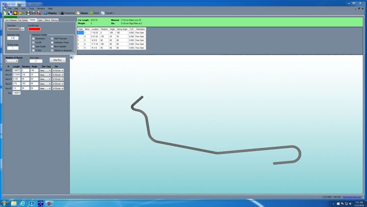
This is a screen shot of the tube after all the information is entered in the software. You can rotate the tube to view if from any angle. This is helpful to make sure you have the rotations and bends going in the right direction.
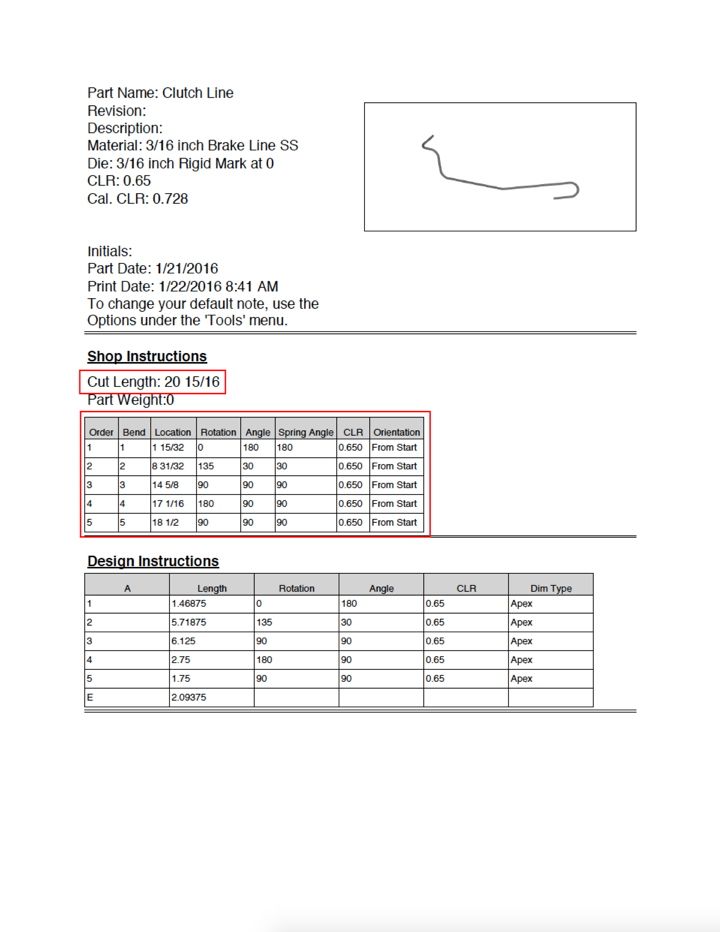
This is the report that you can obtain from the software to take into the shop for fabrication. It provides you with the cut length needed (helps to avoid waste) and shop instructions to fabricate the part. It provides you with the dimensions from the starting end to the location of each bend. The dimension corresponds to the location on your bender that you used to calibrate the bender.
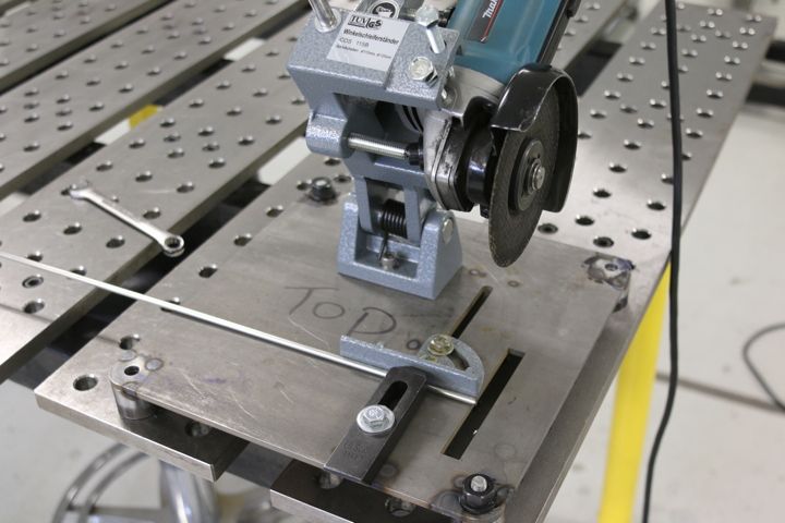
I use a miniature cutoff saw to cut the tubing. This tool, from Grizzly Tools, allows you to use a 4-1/2 hand grinder as a cutoff saw. In this case I'm using my Makita. I'm using stainless steel and it is a little harder to work with.

This is the end of the tube after it is cut. It needs to be de-burred.
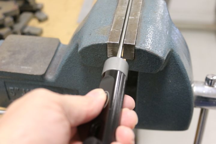
I de-burr the cut end with this tool from The Eastwood Company.
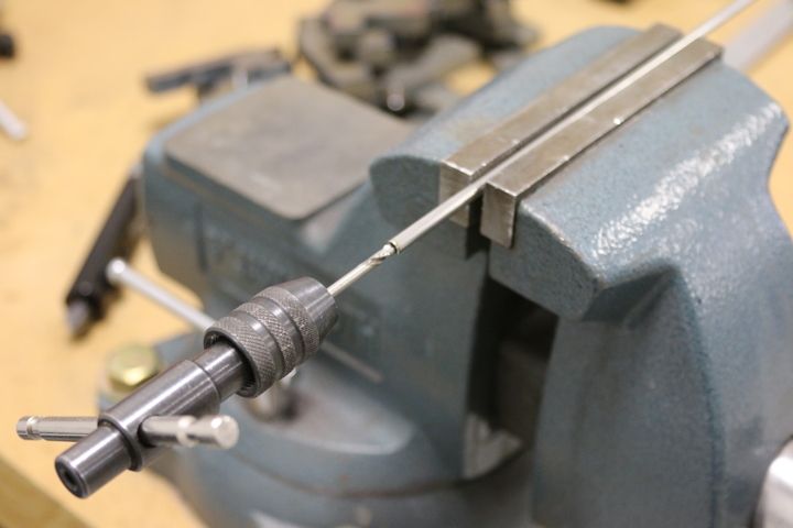
I use a drill bit to de-burr the inside of the tube. A number 30 drill bit works good for 3/16" tubing. A number 11 drill bit works good for 1/4" tubing.
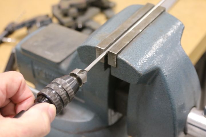
I then complete the de-burring process with a countersink.
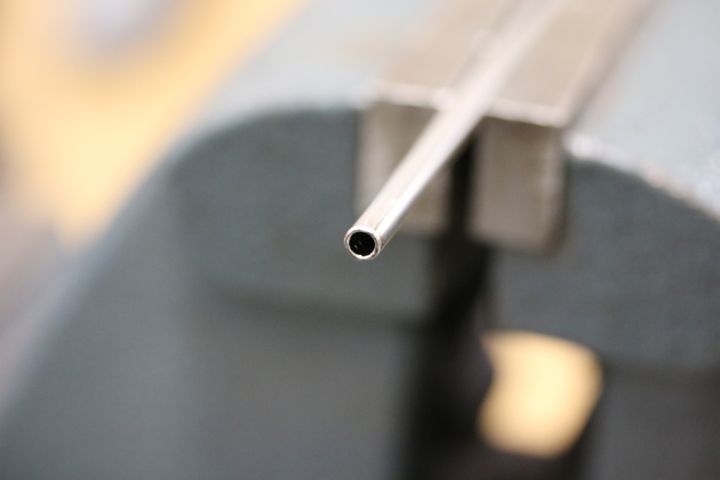
The resulting end after de-burring. Now ready to be flared.

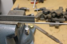
Using a square to measure accurately from the starting end I lay out the location of each bend. These are marked with a fine-tip Sharpie.
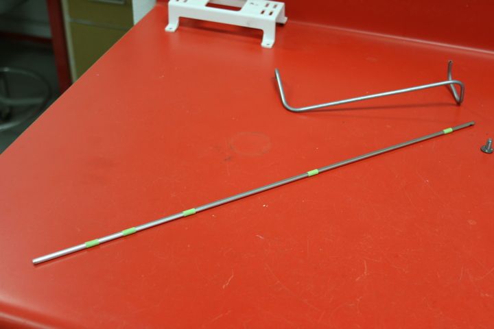
After each bend is located I wrap a piece of masking tape around the tube. This allows me to mark the location of each bend completely around the tube. This is important as a bend may need to be rotated and a simple tick mark on the the tube is not adequate to precisely locate it in the bender.

After marking the location of each bend completely around the tube I remove the masking tape.

Stainless steel tubing is much more difficult to work with than plain steel. To make the flared ends I use this hydraulic flaring tool from Mastercool. In order to get the first bend as tight to the flare nut as possible I will flare the the starting end first.
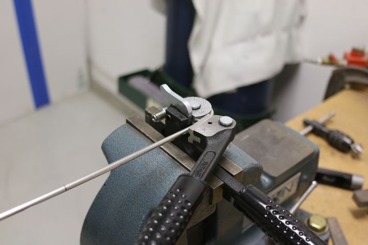
Making the first bend. In this case it's 180 degrees. Note that I installed the flare nut first. I've been know to forget this step and it's hard to add them later. I'm using a Rigid tubing bender with a 5/8" radius. It's about the tightest radius I've been able to find for 3/16" brake tubing.
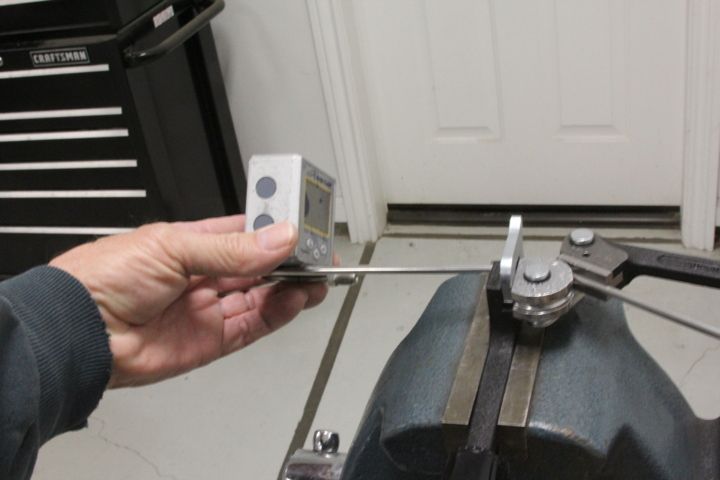
This is the second bend. In this case I needed to rotate the bend 135 degrees. Ninety degree rotations are easy to do by eye. I use a small digital angle finder on other rotations.
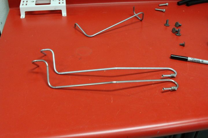
Here's the finished line before installing the second flare nut. Since stainless steel tubing is much more expensive than regular steel tubing I make a prototype line first in regular steel to confirm my dimensions, angle of bend and rotations. Here the stainless steel line (in the foreground) is compared with the standard steel prototype.
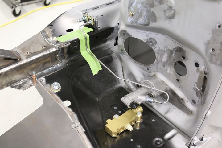
The finished line installed. The green masking tape was used to help me layout the line. The body is on its side in a rotisserie to make it easier to work in the engine compartment.
Thank you for viewing. Please offer up any questions that you may have. I'm also open to feedback as to how to simplify and improve my work.
Britt
I thought it might be of value to document how I used the Bend-Tech software and the steps I take to make hydraulic and fuel lines for my 1967 Ford Mustang Fastback project. If anyone has any ideas for improvement I'm all ears. I still have fuel lines to fabricate.
The example here is the hydraulic line running from the clutch master cylinder to a bracket on the frame rail to which a hose will connect from the hydraulic throwout bearing.
After taking measurements in the engine compartment I designed the tube in Bend-Tech 7x SE. Using the Custom Part interface you enter the beginning length, the angle of rotation of the bend, the angle of the bend and the ending length. The ending length for a previous bend becomes the beginning length for the subsequent bend.

This is a screen shot of the tube after all the information is entered in the software. You can rotate the tube to view if from any angle. This is helpful to make sure you have the rotations and bends going in the right direction.

This is the report that you can obtain from the software to take into the shop for fabrication. It provides you with the cut length needed (helps to avoid waste) and shop instructions to fabricate the part. It provides you with the dimensions from the starting end to the location of each bend. The dimension corresponds to the location on your bender that you used to calibrate the bender.

I use a miniature cutoff saw to cut the tubing. This tool, from Grizzly Tools, allows you to use a 4-1/2 hand grinder as a cutoff saw. In this case I'm using my Makita. I'm using stainless steel and it is a little harder to work with.

This is the end of the tube after it is cut. It needs to be de-burred.

I de-burr the cut end with this tool from The Eastwood Company.

I use a drill bit to de-burr the inside of the tube. A number 30 drill bit works good for 3/16" tubing. A number 11 drill bit works good for 1/4" tubing.

I then complete the de-burring process with a countersink.

The resulting end after de-burring. Now ready to be flared.

Using a square to measure accurately from the starting end I lay out the location of each bend. These are marked with a fine-tip Sharpie.

After each bend is located I wrap a piece of masking tape around the tube. This allows me to mark the location of each bend completely around the tube. This is important as a bend may need to be rotated and a simple tick mark on the the tube is not adequate to precisely locate it in the bender.

After marking the location of each bend completely around the tube I remove the masking tape.

Stainless steel tubing is much more difficult to work with than plain steel. To make the flared ends I use this hydraulic flaring tool from Mastercool. In order to get the first bend as tight to the flare nut as possible I will flare the the starting end first.

Making the first bend. In this case it's 180 degrees. Note that I installed the flare nut first. I've been know to forget this step and it's hard to add them later. I'm using a Rigid tubing bender with a 5/8" radius. It's about the tightest radius I've been able to find for 3/16" brake tubing.

This is the second bend. In this case I needed to rotate the bend 135 degrees. Ninety degree rotations are easy to do by eye. I use a small digital angle finder on other rotations.

Here's the finished line before installing the second flare nut. Since stainless steel tubing is much more expensive than regular steel tubing I make a prototype line first in regular steel to confirm my dimensions, angle of bend and rotations. Here the stainless steel line (in the foreground) is compared with the standard steel prototype.

The finished line installed. The green masking tape was used to help me layout the line. The body is on its side in a rotisserie to make it easier to work in the engine compartment.
Thank you for viewing. Please offer up any questions that you may have. I'm also open to feedback as to how to simplify and improve my work.
Britt