To avoid these ads, REGISTER NOW!

My welding / layout table build. A nod to NastyZen

desmato

Active member
Joined
Oct 15, 2016
Messages
28
Location
Mid Michigan
Ok, so finally got all my poop in a group and started on the table. I want to thank everyone who posts their tables and designs with a special thanks to Claude (Nastyzen) as my build closely mimics his design.

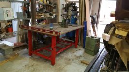
To start, I scored a 1" thick 4x8 plate for 1/8 the cost of new. The legs are 3" 1/8 wall and the rest is 2" 3/16 wall.

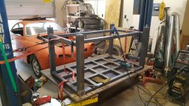
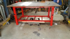
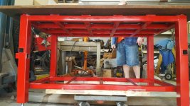
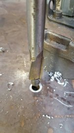
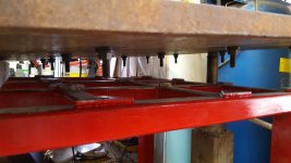
I will be supporting the top with bolts like Claude did and also drilling / tapping 1/2 x 13 holes on 6" centers. It's pretty flat but nothing is perfect so the support system will be great to keep it plumb. I am using 1" cutoffs to plug the bottom of the legs and drill + tapping for 3/4 x 10 bolts as feet. No provision for casters as it will be stationary.

Since I don't need nor have the room for 4x8, I had it cut to 4x6. The base structure will be 3x5.

I will be posting pics of course.
 
To avoid these ads, REGISTER NOW!

ddawg16

Well-known member
Joined
Jul 11, 2008
Messages
21,005
Location
S. California
I've been to Natzy's place. Fantastic metal skills....and a really cool garage...both of them

And you should see his tree house....
 

joe49

Well-known member
Joined
Sep 25, 2009
Messages
1,883
Location
Tonica, Il
Couple of things, A shelf with or a center post so you can move your table with a floor jack. Also only 3 of the legs need be adjustable, then any heavy hammering can be done over the solid leg. I think it would be better to level vs plumb your table.
 
OP
D

desmato

Active member
Joined
Oct 15, 2016
Messages
28
Location
Mid Michigan
Joe, since my floor has ~ 1/4 - 1/2" pitch, I wanted all 4 legs to be adjustable + I wanted to be able to tweak the top plate to as flat as possible (Plumb ?) It will have a lower shelf and cross bar in case I need to jack it up. I just didn't want all the hassle of casters and a movable system plus the clearance issues they present. the old KISS method.
I am a blacksmith and have 3 anvils + 5 post vices, I got the hammering thing covered :thumbup:

sberry, I'm 6'3" and still thought that 4' would be a stretch but where it's going, I will have access to the other side.


PICS !!!!

The "PLATE" .... good thing I have a hoist ! question, how do you build a welding table without having a welding table?
 

Attachments

  • heavy honey.jpg
    heavy honey.jpg
    151.1 KB · Views: 331
Last edited:
OP
D

desmato

Active member
Joined
Oct 15, 2016
Messages
28
Location
Mid Michigan
I cut a slice off the 2' drop from the original 8' section. these will be used as plugs in the leg bottoms. tapped to 3/4-10 and using bolts for the feet. I wanted a smooth leg with no plate to catch **** on the bottom so I am plug welding these in. Man that took some time to cut, square, drill, ream and tap ... If only I had a MILL !

No I didn't use the cutoff wheel and yes I know it has the guard removed, don't judge.

You can just see one of the porta-band saws I have in the background (painted yellow) which is what I used to make the slice. not perfect, but both my oxy bottles were empty and my plasma wouldn't come close to 1"
 

Attachments

  • 3:4 tap.jpg
    3:4 tap.jpg
    145.1 KB · Views: 256
  • hand ream to 21:32.jpg
    hand ream to 21:32.jpg
    143.2 KB · Views: 246
  • chips.jpg
    chips.jpg
    148.1 KB · Views: 261
  • lego blocks.jpg
    lego blocks.jpg
    139.4 KB · Views: 234
  • slice.jpg
    slice.jpg
    144.3 KB · Views: 270
Last edited:
OP
D

desmato

Active member
Joined
Oct 15, 2016
Messages
28
Location
Mid Michigan
Steel, lots-o-steel...

Glad I have that horizontal bandsaw ! it's a Wilton but made in Taiwan.... go figure.
 

Attachments

  • mucho cutt-o.jpg
    mucho cutt-o.jpg
    147.6 KB · Views: 148
Last edited:
OP
D

desmato

Active member
Joined
Oct 15, 2016
Messages
28
Location
Mid Michigan
Here's the layout (top view) showing the plate as the outline, and the support structure. this is where the similarity to Claude's build starts to show.
 

Attachments

  • drawring.jpg
    drawring.jpg
    142.4 KB · Views: 177
OP
D

desmato

Active member
Joined
Oct 15, 2016
Messages
28
Location
Mid Michigan
Progress for the day.....
 

Attachments

  • she's got legs.jpg
    she's got legs.jpg
    143.3 KB · Views: 210
  • plug that weld.jpg
    plug that weld.jpg
    136 KB · Views: 217
  • dead one of these.jpg
    dead one of these.jpg
    152.5 KB · Views: 241
OP
D

desmato

Active member
Joined
Oct 15, 2016
Messages
28
Location
Mid Michigan
I knew someone would spot the elephant in the corner. that Ghia is a '67 on a '69 pan. I wish I had the orig pan since the numbers don't match but alas, I have a Ghia. I just finished the entire bottom (Pan, suspension, drivetrain etc.) and now moving on to the body, which was on the hoist a week ago but needed set back down for the table build.

Claude, It will have power and air at some point. right now it needs finished and put in it's spot. the compressor sits 2' from where the table will be (noisy for sure) and I have 110 and 220 plugs about the same distance so I am good for now. Or are you referring to the tube receptacles like you have ? I did give those some serious thought and I love the way your tables turned out. I may regret not doing them..... I can always add them later and may, but for now it will stay simple.
 

NASTYZEN

Well-known member
Joined
Jun 11, 2010
Messages
2,823
Location
St-Colomban,Que. Canada
Yes, tube receptacles is what I meant. I'm constantly using the mid height ones I have. Wish I had added more. Great for hand drilling stuff without having to stand on something to get some weight on the drill.


Hey John, the tree house is still up after 15 years or so. But it's starting to fall apart. I have to tear it down if the snow ever melts.
 
OP
D

desmato

Active member
Joined
Oct 15, 2016
Messages
28
Location
Mid Michigan
progress for the day, again, for the 2nd time...

Claude, you talked me into putting 3 receivers in the legs, simply because I only have enough scrap from the two 24' bars for 3.

Everything is welded except the receivers and "biscuits" which I just finished cutting. need to grind a few of the welds on top so the biscuits sit flat.

Ran out of wire and gas plus was missing the 3/8 flat stock for the biscuits, so..... road trip. got the new 12lb spool of wire out of the box and promptly dropped in on the floor !!!!! DOH. now the plastic spool is split and won't feed without constant attention and it shows in some of my welds. gunna try to wind it all on the old spool, AFTER I'm done with the last bit of welding.

That all said, here's a pic of the stand, on the plate, on the hoist. hopefully tomorrow, I will have that order reversed and in it's final resting place.

Todd
 

Attachments

  • 20170404_193157_resized.jpg
    20170404_193157_resized.jpg
    151.6 KB · Views: 253

gte718p

Well-known member
Joined
Mar 12, 2009
Messages
3,950
That is an awesome start to the table. I would consider spending the money to get it ground flat. It is not 100% necessary depending on the kind of work you plan on doing on the table. However, once you have worked on one it is hard to go back.
 

MarkG

Well-known member
Joined
May 23, 2012
Messages
1,219
Location
Elgin, IL
I never understood the obsession with precise 'flatness' on a welding table, since every weld you make distorts the work or puts some tension in it. Unless the idea is simply to use it as a reference to see how much that last weld really distorted the workpiece......
 
To avoid these ads, REGISTER NOW!

gte718p

Well-known member
Joined
Mar 12, 2009
Messages
3,950
I never understood the obsession with precise 'flatness' on a welding table, since every weld you make distorts the work or puts some tension in it. Unless the idea is simply to use it as a reference to see how much that last weld really distorted the workpiece......

It appears you do understand. When you are doing layout or aligning pieces, starting with a flat surface makes everything easier. Good work starts with a good base. You also have a good reference if things do move as you weld. A flat table also adds to repeat-ability. If you lay out pieces on different areas of the table, they fit together the same way.
 

dr_clyde

Well-known member
Joined
Jan 7, 2009
Messages
6,425
Location
Holland, MI
I never understood the obsession with precise 'flatness' on a welding table, since every weld you make distorts the work or puts some tension in it. Unless the idea is simply to use it as a reference to see how much that last weld really distorted the workpiece......

It makes fixturing easy. Yes, weldments distort. But it is easier to mitigate with a good clamping system.

The flat table is a reference surface. Think of it as a large, conductive surface plate. Measuring from a constant, flat plane will make it much easier and faster to lay out and fit up all kinds of frames, boxes, and other increasingly complex weldments.

For general repair work, unrestrained welding, and "agricultural" welding, it is not needed. When your customer gives you a tolerance to hit, being able to measure and fixture to a consistent surface makes it fast and easy to make good work.
 
OP
D

desmato

Active member
Joined
Oct 15, 2016
Messages
28
Location
Mid Michigan
The cost and necessity of having it ground are just not there. I am not a fab shop nor do I do precision work. I needed a large-ish, close to flat as possible table to do all sorts of welding and layout of larger smithing projects if the need arises. It will also provide a large work "bench" since I'm a gearhead and do ALL sorts of stuff in the shop. I am working on 4 cars and 1 motorcycle so the possible use of it is wide open.

In the attached pic, you can see where I had to ratchet strap the legs to the hoist posts to pull them apart 1/8" to get the bottom bars in place. My welds are square but it's the slight bow in the plate while being suspended from the hoist that caused it. I understand how welds move around and accounted for it in the plans, I just can't see the need for blanchard grinding it..... until I need it !

The top weighs 960# and with 24 suspension points, each will be supporting 40#, which is how much the 1" plate weighs per sq foot. nice simple math.
 

Attachments

  • 20170404_123346_resized_1.jpg
    20170404_123346_resized_1.jpg
    153.8 KB · Views: 182
OP
D

desmato

Active member
Joined
Oct 15, 2016
Messages
28
Location
Mid Michigan
All de-spattered, wire wheeled, wiped down and ready for paint. It dropped to the low 30's yesterday and we got 2" of snow but is supposed to be in the 60-70's and sunny tomorrow/Sunday so paint will happen then.

I'm thinking of covering the top with sheet and I need a sheet for the lower shelf as well. My TIG, MIG and plasma will reside on that shelf so covering the top may be a good idea, just more $ and time

Todd
 

Attachments

  • 20170406_144542_resized.jpg
    20170406_144542_resized.jpg
    148.8 KB · Views: 149
Last edited:
OP
D

desmato

Active member
Joined
Oct 15, 2016
Messages
28
Location
Mid Michigan
It's really nothing more than a copy of Nasty's build, 'cept more basic. The inspiration came from him and the others on this board. I just took the design items I liked and put it together for my build.

Got some sheet for the top covering and bottom shelf. Gunna get them on then prime/paint. no pics until it's at that point which will likely be tomorrow.....

Sorry, just have to wait.
 
OP
D

desmato

Active member
Joined
Oct 15, 2016
Messages
28
Location
Mid Michigan
Painted and in place.....

Now need to drill, countersink & tap the 24 holes for the suspension. drill the nuts/bolts for roll pins, then lift the top off and install the 24 bolts, nuts, washers and roll pins.

Excuse the mess in the shop. much moving of stuff had to occur and everything is just scattered around. And for the record, moving 1240 lbs of steel around is not for the faint of heart !
 

Attachments

  • 20170409_145538_resized.jpg
    20170409_145538_resized.jpg
    147.2 KB · Views: 191
  • 20170409_145544_resized.jpg
    20170409_145544_resized.jpg
    151.8 KB · Views: 165
  • 20170409_153727_resized.jpg
    20170409_153727_resized.jpg
    152.7 KB · Views: 167
Last edited:

NASTYZEN

Well-known member
Joined
Jun 11, 2010
Messages
2,823
Location
St-Colomban,Que. Canada
Making good progress there Desmato, looking great. There will be much less mess once your done with it. Gotta break eggs to make an omelette. (or something like that)
 
OP
D

desmato

Active member
Joined
Oct 15, 2016
Messages
28
Location
Mid Michigan
Claude, the oddest thing... While drilling holes today, I was thinking "gotta break a few eggs". NO JOKE !!

Got the 24 holes drilled and tapped. thank GOD for that mag drill !!!!!! the process was:
* drill all holes to 27/64 through both plate and support for proper alignment, installing unused 27/64 drill bits in holes to keep alignment.
* enlarge holes in plate to 1/2 to allow clearance for tap and 1/2 - 13 bolts plus pilot for ream/counter bore bit
* tap all holes through plate since I was NOT moving it !
* fill 2 gallon bucket with sharp curly metal scrap.
* prepare 3 flute counter bore in mag drill for another round of sound-n-chips some day, just not today.

Need to stop at the local bolt co. for the allen bolts, nuts, washers & roll pins. then done except for bending steel for bottom shelf.

I'm beat, time for whiskey and bed :beer:

Todd
 

Attachments

  • 20170410_160828_resized.jpg
    20170410_160828_resized.jpg
    138.7 KB · Views: 95
  • 20170410_184529_resized.jpg
    20170410_184529_resized.jpg
    150.6 KB · Views: 84
  • 20170410_155602_resized.jpg
    20170410_155602_resized.jpg
    145 KB · Views: 98
Last edited:
OP
D

desmato

Active member
Joined
Oct 15, 2016
Messages
28
Location
Mid Michigan
OK, too l much time has passed and i'm sorry but as most know, life takes over sometimes..... darned responsibilities !

Here's the "final" update to the build. I did not drill/tap all the 1/2 - 13 grid holes and I may not, at least for the time being. Once I make, buy all the clamps, I'll rethink that or if the need arises. I'm still not sure if I want that or the stronghold type system, so....

Here are pics of all the '*******' and of the top, sans removal of the millscale. I guess I still need to set the bottom shelf on as well.

I learned that the top plate is MUCH stronger that the entire sub structure as I am actually tweaking the legs out of square/plumb when 'adjusting' the bolts to make the top flat. Shoulda used a thinner plate !

Todd
 

Attachments

  • 20170417_105544.jpg
    20170417_105544.jpg
    136.6 KB · Views: 124
  • 20170417_190724.jpg
    20170417_190724.jpg
    149.7 KB · Views: 115
To avoid these ads, REGISTER NOW!
Top Bottom