To avoid these ads, REGISTER NOW!

Atlas 64 restoration

GeorgeG2

Active member
Joined
Mar 31, 2017
Messages
41
Location
Melbourne Florida
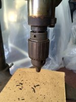
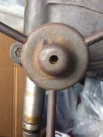
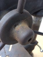
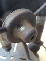
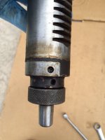
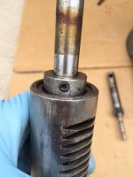
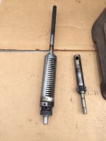
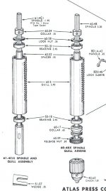
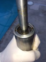
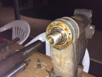
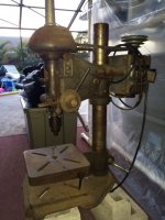
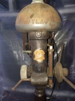
Picked up this Atlas 64 today for my first DP restoration project. The serial number is 057275. The motor is Atlas 25304A-1 which is a 110V 1/2HP. I have a copy of the owners manual and parts list on order. I have a pretty good tool set and level of mechanical experience but this is my first drill press project. The unit runs and the spindle does not have any significant lateral play. I will check the run out tomorrow before I start.

A few starter questions:

1) Does anyone know the date (or range) of manufacture? Most people seem to date their Model 64's in the 1940's. After looking at a bunch of catalogs it looks like the possible date range is 1944 - 1948.

2) Will total disassembly require anything ********* like a hydraulic press?

3) If I run into the need for parts, whats the best source?

4) Can anyone point to a rebuild thread here or otherwise for this or a similar model?

Thanks,

George
 

Attachments

  • IMG_6458.JPG
    IMG_6458.JPG
    106.5 KB · Views: 210
  • IMG_6456.JPG
    IMG_6456.JPG
    118.8 KB · Views: 194
  • IMG_6455.JPG
    IMG_6455.JPG
    89.6 KB · Views: 172
  • IMG_6452.JPG
    IMG_6452.JPG
    116.3 KB · Views: 185
Last edited:
To avoid these ads, REGISTER NOW!

jakemac

Well-known member
Joined
May 21, 2013
Messages
9,035
Location
New England
Atlas was making that model for Craftsman starting in the late 30's. Only the badge and the name in the cast pulley cover are different. With the Cman machines I can date them by the number of handles and the switch plate (oval or rectangle), but atlas did things differently for their DP's than the Cman versions so it wouldn't necessarily translate on the years.

My guess would be early 40's, pre-war, but I could be wrong.
See if there is a date code on the motor plate. That could narrow the range for you.

Other than the bearings, the best source for parts would be eBay. If someone is parting one out. Otherwise, you may need to find a donor.
 
OP
G

GeorgeG2

Active member
Joined
Mar 31, 2017
Messages
41
Location
Melbourne Florida
Combining the information from the dated catalogs and the serial number registry on vintagemachinery.org it looks like my Atlas 64 was built in 1944 during the war (while my father was serving). Definitely meets my objective of having a vintage machine that was built by the greatest generation. Very cool.
 
Last edited:

mikegt4

Well-known member
Joined
Sep 12, 2005
Messages
3,263
Location
sw ohio
My son picked one up last month. His is a bit earlier as there is no grease cap (or any support to grease) at the quill return spring. They are a very basic tool and you should be able to break it down to a pile of parts in 20-30 minutes. Pressing off the bearings might be the only thing that requires much effort, I used a press to remove his. Removing the chuck as the first step might be a good place to start. The bearings are not hard to find although the quill bearings, having a 5/8" ID and metric OD & width require a little searching. The nomenclature for those varies depending on the manufacture, 6202-5/8-RS, 6202-10-RS, 6202RS-5/8, 6202 2RS-10 etc. The spindle bearings are everyday 6204 & 6205 series.

I media blasted the parts for him and he, being in the body shop business, painted them in a nice metallic green finish.

Beware, these are like block grinders, addictive.
 
OP
G

GeorgeG2

Active member
Joined
Mar 31, 2017
Messages
41
Location
Melbourne Florida
In reading a bunch of restoration threads I see that there are a number of ways to strip and where appropriate, polish everything. A couple of questions:

1) For the big cast parts do you guys prefer media blasting, wire wheels/cups, electrolysis, acid, or something else?

2) For the smaller parts is it mechanical or chemical? One guy soaks his small parts in vinegar for 5 days. That's a new one.

3) For the post I'm going to try the drill/plumbers plug/caster set up that I saw. Is there a functional consideration between a rougher satin finish vs a mirror like polish?

Thanks,

George
 

jakemac

Well-known member
Joined
May 21, 2013
Messages
9,035
Location
New England
1) Everyone has their own preferences depending on availability, comfort level, and experience. The right answer is the one that works for you.

2) Same answer. I use a combination of both. EvapoRust or CLR (depending on the finish), wire wheel and buffer.

3) On the post, the smoother the finish, the smoother the action of adjusting the table.
 
OP
G

GeorgeG2

Active member
Joined
Mar 31, 2017
Messages
41
Location
Melbourne Florida
Thanks. With this set up I am supposed to be able to just keep unscrewing the knurled ring above the chuck until the chuck breaks its taper fit and falls off, correct? I have the ring spinning down on the threads but no joy on the chuck breaking loose. Do I need to supplement with one of those fork wedges or get more aggressive with the ring?
 

Attachments

  • IMG_6460.JPG
    IMG_6460.JPG
    91.1 KB · Views: 71

kylerohde

Well-known member
Joined
Dec 9, 2016
Messages
61
Location
Kansas City, MO, USA
Combining the information from the dated catalogs and the serial number registry on vintagemachinery.org it looks like my Atlas 64 was built in 1944 during the war (while my father was serving). Definitely meets my objective of having a vintage machine that was built by the greatest generation. Very cool.

That's very cool. Interesting they were still making them despite the war effort. Wonder if the demand for them was high for use in making things for the war, so it was ok to keep manufacturing the presses themselves too?
 

1930artdeco

Well-known member
Joined
Dec 28, 2010
Messages
1,099
Location
Lynden, Wa
I have the same DP and find that it is a very good press. I knocked the bearings out with a deep well socket.

Mike
 
OP
G

GeorgeG2

Active member
Joined
Mar 31, 2017
Messages
41
Location
Melbourne Florida
The pipe OD is 2.75. Thanks.

How do I safely remove the chuck? I have unscrewed the knurled ring above and made contact with the top of the chuck, but some pretty good force has not knocked it off. Is it just a taper fit? Do I need a wedge and if so does anyone know which Jacobs wedge set is appropriate? I started with 0.003" run out even with pretty noisy bearings so I don't want to guber up the spindle or chuck.

Iv'e done the same using a deep socket with bearings for motor shafts so it sounds like I can do that here also. Thanks.

Thanks,

George
 
Last edited:

bmw57isetta

Well-known member
Joined
Apr 27, 2010
Messages
268
Location
Austin, Texas
GeorgeG2:

First of all, congratulations on scoring a bulletproof drill press. I have the 1941 Atlas/Sears/Dunlap version I've almost finished restoring. It was a disaster area compared to yours.

In regards to the chuck, in a perfect world, that knurled ring is supposed to force the chuck off but after all these years and lack of lube it rarely happens. (Please don't use any Channelocks or Vice-Grips on the knurled knob and mess it up.) First, squirt some sort of penetrating lube (Gibbs, Aerokroil, etc.) on the spindle, below that knurled ring, where the chuck mounts and let it creep down into the chuck.

The easiest way to get it off is to get a set Jacobs chuck removal wedges. That's why they make 'em. Place one on each side of the spindle above the chuck and give each side a few simultaneous whacks and the chuck should pop off. Be sure to have a towel or another pair of hands under the chuck to keep it from hitting the floor. You can get those wedges on Amazon, Zoro tools or through Jacobs direct. A well-stocked Ace Hardware may have them too. Should run you around $15-$20 for the pair. I think your DP will need a #6 wedge set. The Jacobs site will have a list of what chuck model numbers require a specific wedge number. They sure made the job easy for me on three occasions.

There are some other methods to do it without the wedges but I'll leave that up to other GJ'ers to chime in on what worked for them.
 
OP
G

GeorgeG2

Active member
Joined
Mar 31, 2017
Messages
41
Location
Melbourne Florida
I finally found some dimensions for those Jacobs wedges so I'll go measure my DP today and order the correct ones. Thanks.

George
 
OP
G

GeorgeG2

Active member
Joined
Mar 31, 2017
Messages
41
Location
Melbourne Florida
Next up is getting the spindle and quill out. First I need to remove the spindle feed assembly but in order to do that I have to remove the hub and handles on the right side so that the feed assembly can slide out to the left away from the hub. It looks like there is a large pin through the hub and shaft.

Is that an interference fit? If so which way do I tap it out. I tried force on the side where the pin is depressed into the hub as apposed to the other side where the pin is more or less flush with the hub and maybe even mushroomed a little. No movement. Any advice on how to move this thing safely?

Thanks,

George
 

Attachments

  • IMG_6469.JPG
    IMG_6469.JPG
    90.6 KB · Views: 55
  • IMG_6470.JPG
    IMG_6470.JPG
    85.5 KB · Views: 52

nine4gmc

Well-known member
Joined
Mar 24, 2012
Messages
14,357
Location
Dallas
George, I think there is a set screw in the center hole there holding that pin in place. Remove the set screw, then punch the pin out.
 
OP
G

GeorgeG2

Active member
Joined
Mar 31, 2017
Messages
41
Location
Melbourne Florida
George, I think there is a set screw in the center hole there holding that pin in place. Remove the set screw, then punch the pin out.

Thanks, I see that. In my case however, the set screw is missing. How do you guys recommend that I get the pin out of the hub and shaft? I tried a punch and some pounding but no movement. Also, which way does this pin come out? I tried the depressed end.

Thanks,

George
 

Attachments

  • IMG_6472.JPG
    IMG_6472.JPG
    97.4 KB · Views: 42
  • IMG_6470.JPG
    IMG_6470.JPG
    85.5 KB · Views: 42
  • IMG_6469.JPG
    IMG_6469.JPG
    90.6 KB · Views: 46

bmw57isetta

Well-known member
Joined
Apr 27, 2010
Messages
268
Location
Austin, Texas
After soaking the area around that pin with Gibbs Penetrant, top and bottom, I let it sit overnight and punched it out the next day with a Starrett pin punch. I have attached an exploded diagram of the 64 spindle feed assembly for your viewing pleasure. (http://vintagemachinery.org/pubs/detail.aspx?id=10550) The pin doesn't appear to be tapered. The three I've had to remove from various drill presses were the same size top-to-bottom.

Thanks for keeping us posted on your progress. Patience is your best friend. That's going to be a nice drill press when you're done with it.
 

Attachments

  • Atlas Spindle Feed Diagram.JPG
    Atlas Spindle Feed Diagram.JPG
    41.6 KB · Views: 81
To avoid these ads, REGISTER NOW!
OP
G

GeorgeG2

Active member
Joined
Mar 31, 2017
Messages
41
Location
Melbourne Florida
Two days of penetrant and a 3/8" Starrett punch and the hub pin is out. Thank you.

On to the spindle and quill. I got the assembly out and I got the collar at the top of the spindle off (just above the lock ring that seat into the top of the quill). How do I get the rest of the spindle/quill apart?

I took the set screw out of the spindle pulley but the pulley wont budge. How do I get that safely off?

Thanks in advance. I want to make sure that I don't screw up this excellent DP as I break apart 73 years of history.

George
 

Attachments

  • IMG_6494.JPG
    IMG_6494.JPG
    88.5 KB · Views: 56
  • IMG_6493.JPG
    IMG_6493.JPG
    78.1 KB · Views: 54
  • IMG_6491.JPG
    IMG_6491.JPG
    79.1 KB · Views: 58
  • IMG_6490.JPG
    IMG_6490.JPG
    71.7 KB · Views: 52
  • IMG_6489.JPG
    IMG_6489.JPG
    80.2 KB · Views: 52
  • IMG_6488.JPG
    IMG_6488.JPG
    91.7 KB · Views: 66
Last edited:

bmw57isetta

Well-known member
Joined
Apr 27, 2010
Messages
268
Location
Austin, Texas
GeorgeG2:

Congrats on getting that pin out. In regards to breaking the spindle assembly down I attached another exploded diagram from the 64 manual. Your spindle is the one on the right. You mentioned you had removed the locking collar above the split ring on top of the quill but it looks to me like it's still there in the middle and right pic on the top row you posted. Note that there's a lock nut under that collar that needs to come off too. http://vintagemachinery.org/pubs/detail.aspx?id=10550. (Click on "View PDF" then scroll down to pages 6 and 7). Once those have been removed the quill should slide out the top of the spindle. Once again, some penetrant might be in order as there are also two bearings, one bottom, one top, that are integral to the quill.

In regards to your pulley not coming off, if you look at the pulley diagram on Page 7 (also posted below) you'll see there's a sleeve that fits into the pulley. Again, use some penetrant through the hole in the top of the pulley. Be extremely careful getting it off. You might gently try to rock it from side to side by hand to break any crud that may be holding it on the sleeve.

Please report back when convenient. You're getting there and doing the right thing by asking good questions.
 

Attachments

  • Atlas Spindle Assembly.JPG
    Atlas Spindle Assembly.JPG
    61 KB · Views: 59
  • Atlas Pulley Assembly.JPG
    Atlas Pulley Assembly.JPG
    46.3 KB · Views: 55
OP
G

GeorgeG2

Active member
Joined
Mar 31, 2017
Messages
41
Location
Melbourne Florida
Yes the collar is in my picture but I removed it after I took the photo. Is the locking ring at the top of the quill (under the now removed collar), threaded? What do you use to unscrew that without ruining the threads as I have tried a few things and it wont budge.

I finally got the top pulley off. It looks like I have to pound the top spindle bearing assembly out of the body from underneath (with say a big wooden dowel) now that the pulley and bearing plate are removed. Is that correct?

Thanks,

George
 

Attachments

  • IMG_6495.JPG
    IMG_6495.JPG
    67.6 KB · Views: 53
  • IMG_6498.JPG
    IMG_6498.JPG
    82.5 KB · Views: 54
Last edited:

mikegt4

Well-known member
Joined
Sep 12, 2005
Messages
3,263
Location
sw ohio
GeorgeG2
Could you measure the length of the 2.75" pipe? The Atlas DP that my son bought was "converted" to a floor model by using a 6-1/2' long pipe (yikes!) at some point in it's life. Very unstable and he would like to return it to a bench model by cutting down the pipe to the original length.
 

bmw57isetta

Well-known member
Joined
Apr 27, 2010
Messages
268
Location
Austin, Texas
GeorgeG2: The diagram would suggest that the locking ring is threaded. It appears to be a removal job for a spanner wrench. Once you hit it with some sort of lube, you might get lucky and carefully tap the recesses on either side at an angle with a pin punch and get it out that way but it looks like a pin spanner is the way to go.

Since you got that locking collar off, the quill may slide up the spindle shaft as-is which would allow you to remove the locking ring after the fact. That locking ring is in there to keep the quill and bearings together when in operation. Again, lube/penetrant is your friend here. I prefer to take some #000 steel wool dipped in acetone and shine the spindle up from above the quill to the top of the shaft so there isn't any gunk or obstruction that would get in the way when you slide it off.

You might give that a try before you go off and buy another tool. On the other hand, this may be another textbook example of how GJ ends up costing you every time you turn around. Like those #6 wedges for instance. It's happened to all of us.

FYI: Here's a fixed length spanner on the left and an adjustable spanner on the right. $20-$30'ish depending on where you buy them.
 

Attachments

  • Pin Spanner.JPG
    Pin Spanner.JPG
    21 KB · Views: 32
  • Pin Spanner Adjustable.JPG
    Pin Spanner Adjustable.JPG
    18.5 KB · Views: 33

jakemac

Well-known member
Joined
May 21, 2013
Messages
9,035
Location
New England
Go to a good bicycle shop. If you're lucky, they'll carry Parks pin spanners. They may cost less, and still get the job done. Get the SPA-1 model. The pins are 2.9mm and the arms can be spread to fit. Should cost $15 or less.
 
Last edited:
OP
G

GeorgeG2

Active member
Joined
Mar 31, 2017
Messages
41
Location
Melbourne Florida
GeorgeG2
Could you measure the length of the 2.75" pipe? The Atlas DP that my son bought was "converted" to a floor model by using a 6-1/2' long pipe (yikes!) at some point in it's life. Very unstable and he would like to return it to a bench model by cutting down the pipe to the original length.

30.125". Good luck.

George
 
OP
G

GeorgeG2

Active member
Joined
Mar 31, 2017
Messages
41
Location
Melbourne Florida
Go to a good bicycle shop. If you're lucky, they'll carry Parks pin spanners. They may cost less, and still get the job done. Get the SPA-1 model. The pins are 2.9mm and the arms can be spread to fit. Should cost $15 or less.

SPA-1 on order, thanks. I confirmed that this version will work as the slots in the lock nut are 3.2mm.

BTW, old news for you many of you guys but for the other newbies that follow and may be reading this I found that when you have to knock out a tough pin, you get better results when your flat punch is closer to the pin diameter. I didn't have anything close to the 7/16" pin in that hub so I bought a 3/8" Starrett punch and the increased energy transfer was obvious.

George
 
OP
G

GeorgeG2

Active member
Joined
Mar 31, 2017
Messages
41
Location
Melbourne Florida
It will be on to bearing selection and replacement soon. Any advice on what I should use? The originals are SKF which I see are still commonplace but they have several grades (RS?). I don't know if they are still made in the USA. Some say that they only use Japanese bearings. I see names like Koyo and VXB/Nachi.

Also whats better the ones sealed with metal plates or rubber?

Thanks,

George
 
Last edited:

mikegt4

Well-known member
Joined
Sep 12, 2005
Messages
3,263
Location
sw ohio
30.125". Good luck.

George

thanks

6.5 feet of pipe balancing on a "bench" size base isn't very stable. Luckily the DP runs very smooth. The PO owned it for 25 years and it came to him like that, he bought it from a machine shop. Notice the pipe goes up and out of the photo. This is how it came to my son.
 

Attachments

  • 00y0y_6w3RXhLr6OF_1200x900.jpg
    00y0y_6w3RXhLr6OF_1200x900.jpg
    70.7 KB · Views: 52

jetlag

Well-known member
Joined
Feb 26, 2008
Messages
114
Location
Centralia,Wa
They may have used single sided ( z suffix) bearings, but you want to avoid that, unless you want to periodically clean and lubricate your bearings. The numbering system for ball bearings is pretty simple. You'll probably be using 6200 series ball bearings for your drill.
6: first digit in this case is single row, deep groove ball bearing.
2: second digit indicates a light duty bearing (6000 series is extra light, 6300 series is medium duty)

The last two digits indicate internal bore: 00-03, the ID is 10, 12, 15, 17 consecutively. 04 and up, multiply the digit by 5. The outside diameter and the bearing thickness is also standardized, but you need to look it up on a chart.

The suffix indicates the type of seal z suffix is single sided metal shield. zz suffix denotes a metal shield on both sides, and 2RS is rubber sealed on both sides.

The type 6 bearing series bearings are very, very common. Measure your bearings, and you can pretty much look up the bearing number you'll need. SKF also has a bearing calculator for Iphone and Android. Inch bearings generally start with an "R" followed by numbers, which denote shaft size in 16ths of an inch. A R8 bearing would have a 1/2" (8/16ths) bore.

For your drill rebuild, I'd probably use zz bearings.
 

jetlag

Well-known member
Joined
Feb 26, 2008
Messages
114
Location
Centralia,Wa
Did you get your spindle pressed out of the quill body? One of my friends pointed a youtube video out to me, which showed some guy whacking a spindle out of a quill with a hammer. ouch! Sometimes an older quill/spindle can be a little difficult to separate. But nevertheless, you need to carefully press them apart, to avoid possibly bending the spindle.

Once your spindle is out, and if you have access to a lathe, chuck it up in a 4 jaw, dial it in, and check the runout. If it is a little bent, you can straighten them out sometimes by applying heat with a pinpoint torch on the high side (just a little bit), then quenching with a wet rag.
 
OP
G

GeorgeG2

Active member
Joined
Mar 31, 2017
Messages
41
Location
Melbourne Florida
Did you get your spindle pressed out of the quill body? One of my friends pointed a youtube video out to me, which showed some guy whacking a spindle out of a quill with a hammer. ouch! Sometimes an older quill/spindle can be a little difficult to separate. But nevertheless, you need to carefully press them apart, to avoid possibly bending the spindle.

Once your spindle is out, and if you have access to a lathe, chuck it up in a 4 jaw, dial it in, and check the runout. If it is a little bent, you can straighten them out sometimes by applying heat with a pinpoint torch on the high side (just a little bit), then quenching with a wet rag.

This is the last thing that needs to come apart, I am waiting on my spanner wrench. Thanks for the tips.

George
 
OP
G

GeorgeG2

Active member
Joined
Mar 31, 2017
Messages
41
Location
Melbourne Florida
The spanner did the trick on the threaded lock ring - thank you. So now I have an exposed bearing in the top of the quill/spindle and a collar still in place just under the quill at the bottom of the spindle (just above the chuck taper, it looks pinned to the spindle). It looks like the spindle should slide down/quill up until they seperate. Is that correct. I cant get them apart even with some downward force at the top of the spindle (medium tapping with a wooden block).

Any guidance here?

Thanks,

George
 

jakemac

Well-known member
Joined
May 21, 2013
Messages
9,035
Location
New England
Glad the spanner worked for you. Parks pin spanners tend to get overlooked by tool guys because they're considered "bicycle" tools and not "real" tools. That thought is wrong. If it gets the job done, it's the right tool for the job.

Wish I could help you with the quill/spindle issue, but I've never taken a DP apart yet.
There have been a few Atlas and Craftsman/Atlas DP rebuilds posted. Look for those threads and see if they covered that issue. If not, try contacting the member to see if they know how to get them apart.
 
Last edited:
OP
G

GeorgeG2

Active member
Joined
Mar 31, 2017
Messages
41
Location
Melbourne Florida
Everything that I have seen so far suggest that I should be able to pound the spindle down and out of the bottom of the quill. Guess I need to increase the persuasion.
 
OP
G

GeorgeG2

Active member
Joined
Mar 31, 2017
Messages
41
Location
Melbourne Florida
10-4 on the penetrating oil.

I don't care for the videos that have these guys pounding on the top of a foot of unsupported spindle so after talking to a machinist friend, I am going to invert the whole affair and clamp the spindle with some channeled wood blocks a few inches from the quill at the new bottom and pound on the quill at the taper chuck end with a hardwood block bored out to fit over the spindle and chuck collar and bear on the quill). I really don't want to destroy my starting 0.003" (with bad bearings) run out.
 
To avoid these ads, REGISTER NOW!
Top Bottom