To avoid these ads, REGISTER NOW!

My Prentiss Vise Restoration: The Journey

Mark in Indiana

Well-known member
Joined
Aug 11, 2010
Messages
3,057
Location
Southern Indiana
THE START OF THE VISE RESTORATION JOURNEY!

Hello Vise Friends,

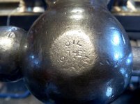
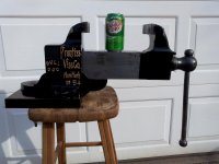
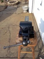
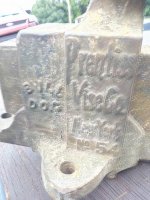
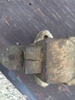
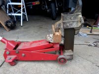
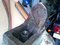
This is my story about a very challenging vise restoration. The vise is a Prentiss No. 54 Bulldog vise, manufactured by The Prentiss Vise Co, New York, NY, in the 1920s. I won it at an auction knowing that it had a large crack along the tip of the slide. However, the vise had beautiful embellishments on the body, it was big and heavy, I needed a restoration challenge and it needed a home.

This vise had seen a VERY HARD life by people who used big hammers. The purpose in creating this thread is to journey through this vise restoration and show how I addressed the following problems:
1. The large crack in the slide.
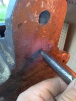
2. The small crack in the body.
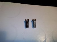
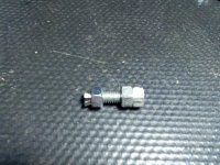
3. Extracting a broken jaw face screw.
4. Making a new jaw face screw.
5. Bent main screw.
6. Damaged nut.
7. Damage from big hammers.
8. Making this vise aesthetically pleasing.

Here are some other specifications:
* Jaw information;
Width = 5".
Opening = 7-3/4".
Depth = 3-5/8".
* Features replaceable jaw faces.
* Solid mount.
* Weight = 70 pounds.


Note: Some of the information here was already posted on the Vise Repair 101 thread and other threads to discuss some of the individual repairs.

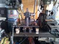
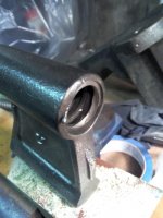
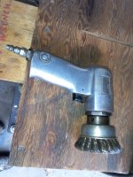
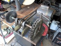
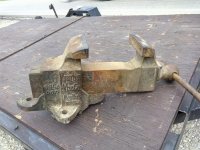
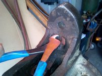
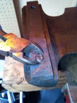
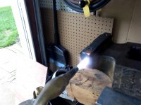
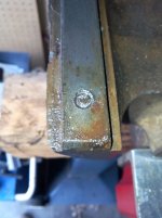
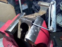
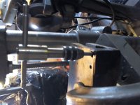
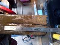
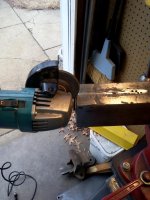
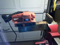
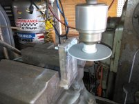
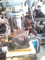
The pictures below are of the Prentiss vise as purchased, before disassembly.


My next post will tell of the disassembly.
 

Attachments

  • A1 PRENTISS 54A.jpg
    A1 PRENTISS 54A.jpg
    147.4 KB · Views: 265
  • A2 PRENTISS 54B.jpg
    A2 PRENTISS 54B.jpg
    147.6 KB · Views: 234
  • A3 PRENTISS 54x.jpg
    A3 PRENTISS 54x.jpg
    148.3 KB · Views: 250
To avoid these ads, REGISTER NOW!
OP
M

Mark in Indiana

Well-known member
Joined
Aug 11, 2010
Messages
3,057
Location
Southern Indiana
PRENTISS VISE DISASSEMBLY 1


The disassembly and inspection will tell how much of a restoration adventure that's in store for me.

1st. Picture:
Since the cracked section if the slide caused it to be wider than normal, I had to push the slide out with a hydraulic floor jack. As the moving jaw would bind up while pushing it with the jack, I would release the hydraulic pressure, hitting it with a soft blow hammer and continue to press out the slide. Later on I will discover that the slide edges were slightly mushroomed out from being used as an anvil.

2nd. - 4th. Pictures:
No way to remove the vise retainer pin without some heat.


More disassembly on my next post.
 

Attachments

  • B1 PRENTISS 54C.jpg
    B1 PRENTISS 54C.jpg
    146.4 KB · Views: 250
  • B2PBD54 SPINDLE NUT1.jpg
    B2PBD54 SPINDLE NUT1.jpg
    136.5 KB · Views: 220
  • B4 PBD54 SPINDLE NUT4.jpg
    B4 PBD54 SPINDLE NUT4.jpg
    136.1 KB · Views: 208
  • B5 PBD54 SPINDLE NUT3.jpg
    B5 PBD54 SPINDLE NUT3.jpg
    134 KB · Views: 205
Last edited:
OP
M

Mark in Indiana

Well-known member
Joined
Aug 11, 2010
Messages
3,057
Location
Southern Indiana
PRENTISS VISE DISASSEMBLY 2

So now I have to extract a broken jaw face screw. Sometimes they come out easily and other times it's like fighting all forces of nature and the universe.

1st. Picture:
Here's the broken screw telling me to give it my best shot.

2nd picture:
Oxygen/Acetylene torch to heat things up.

3rd & 4th, Pictures:
Since things are hot (the metal around the screw has expanded), I can start turning the screw with a scratch awl. After that I take a pair of very sharp side cutters, grab the screw, and finish removing it from the jaw body.

5th. Picture:
Disassembly complete.


In my next post I'll start on the slide repair.
 

Attachments

  • B105 PBD54 DISASSEMBLED.jpg
    B105 PBD54 DISASSEMBLED.jpg
    146.9 KB · Views: 225
  • B94 PBD54 JAW SCREW5.jpg
    B94 PBD54 JAW SCREW5.jpg
    142.5 KB · Views: 213
  • B83 PBD54 JAW SCREW3.jpg
    B83 PBD54 JAW SCREW3.jpg
    128.1 KB · Views: 209
  • B72 PBD54 JAW SCREW2.jpg
    B72 PBD54 JAW SCREW2.jpg
    133.8 KB · Views: 207
  • B61 PBD54 JAW SCREW1.jpg
    B61 PBD54 JAW SCREW1.jpg
    134.5 KB · Views: 214
Last edited:
OP
M

Mark in Indiana

Well-known member
Joined
Aug 11, 2010
Messages
3,057
Location
Southern Indiana
PRENTISS VISE SLIDE REPAIR: 1

I'll have to admit that I was a little intimidated with the challenge of repairing the crack in the slide. Any vise repair must be functional and aesthetically pleasing. Previously, I've turned down vises that had the same problem. Now that I've repaired a cracked slide, I'll be able to buy more Prentiss vises.

Slide cracks are caused by a thinner area that was cast in the moving jaw body. Also, using the slide as an anvil...which is a big no-no.

1st. & 2nd. Pictures:
The entire crack is almost 5” long and causes the width of the slide to be .110” wider than it should be.

To make the repair, I'll drill, thread and countersink a hole to place a 1/4”-20 Grade 8 socket head cap screw (SHCS) in the end of the slide. The SHCS will pull the crack together at the end of the slide.

3rd Picture:
Drilling out the hole. I used a 1/4” drill bit to drill through half of the slide, a #7 drill bit to drill a blind hole into the other half of the slide, and a 3/8” drill bit for a countersink to hide the head of the SHCS.

4th. Picture:
Threading the bottom of the hole for the SHCS. First oil the hole. Using a starter tap, clamp it in the drill chuck. Bring the tap down in the hold to where you want to start threading. Turn the chuck BY HAND until the tap starts to cut threads. This will ensure that the threads that you're cutting are straight. Then release the starter tap from the chuck and continue your thread cutting. After you've bottomed out the starter tap, blow out the hole with compressed air, re-oil the hole and finish the thread with the bottom tap. Blowout the hole again.

5th. Picture:
Clamp the end of the slide in a BF vise. This will ensure that you won't damage your threads when drawing the crack together. Then install your SHCS.

6th. Picture:
This is what the side of the slide looks like.

7th. Picture:
Drill some holes at the small end of the crack to relieve stress and stop the crack from growing.


Really at this point: You could drill a small hole at the other end of the crack, to relieve the stress that would make it grow, and call it done. The SHCS is the repair. However, I want to finish out this vise.


More slide repair in my next post.
 

Attachments

  • C6A PRENTISS SLIDE CRACK REPAIR8.jpg
    C6A PRENTISS SLIDE CRACK REPAIR8.jpg
    142.3 KB · Views: 243
  • C6 PRENTISS SLIDE CRACK REPAIR5.jpg
    C6 PRENTISS SLIDE CRACK REPAIR5.jpg
    139.5 KB · Views: 239
  • C5 PRENTISS SLIDE CRACK REPAIR4.jpg
    C5 PRENTISS SLIDE CRACK REPAIR4.jpg
    89.1 KB · Views: 246
  • C4 PRENTISS SLIDE CRACK REPAIR3.jpg
    C4 PRENTISS SLIDE CRACK REPAIR3.jpg
    66.5 KB · Views: 230
  • C3A PRENTISS SLIDE CRACK REPAIR2.jpg
    C3A PRENTISS SLIDE CRACK REPAIR2.jpg
    133.8 KB · Views: 235
  • C2 MEASURING THE PRENTISS SLIDE CRACK.jpg
    C2 MEASURING THE PRENTISS SLIDE CRACK.jpg
    135.1 KB · Views: 241
  • C1 PRENTISS 54G.jpg
    C1 PRENTISS 54G.jpg
    141.7 KB · Views: 237
OP
M

Mark in Indiana

Well-known member
Joined
Aug 11, 2010
Messages
3,057
Location
Southern Indiana
PRENTISS SLIDE REPAIR 2

Continuing with the slide repair:

1st Picture:
OOPS! I wanted to use 2 SHCS to hold the slide crack together. I drilled without looking and realized that the second hole wouldn't have enough metal to hold a SHCS. To fix this, I tapped a 5/16”-18 thread into the second hole and installed a small screw.

2nd. Picture:
I cut most of the screw off, cut a slot in top of the remaining stud to make a plug, and screwed it below the slide surface. The SHCS and my plug will be soldered over.

3rd. Picture:
It's important to grind a valley into the crack to give more area for the solder or braze to cling to.

4th. Picture:
The crack and holes are soldered. On a side note, I used flux core silver solder, mainly because I have a lot of it. Braze will work as well. Main thing is to be sure that the area to be soldered is clean by burning away the contaminants and using flux as well.


I will finish the slide repair in my next post.
 

Attachments

  • C71 PRENTISS SLIDE CRACK REPAIR6.jpg
    C71 PRENTISS SLIDE CRACK REPAIR6.jpg
    138.9 KB · Views: 209
  • C82 PRENTISS SLIDE CRACK REPAIR7.jpg
    C82 PRENTISS SLIDE CRACK REPAIR7.jpg
    144.1 KB · Views: 205
  • C103 PRENTISS SLIDE CRACK REPAIR11.jpg
    C103 PRENTISS SLIDE CRACK REPAIR11.jpg
    144.3 KB · Views: 230
  • C114 PRENTISS CRACKED SLIDE REPAIR BRAZE.jpg
    C114 PRENTISS CRACKED SLIDE REPAIR BRAZE.jpg
    141.1 KB · Views: 246
OP
M

Mark in Indiana

Well-known member
Joined
Aug 11, 2010
Messages
3,057
Location
Southern Indiana
PRENTISS SLIDE REPAIR 3

Now that the slide has cooled down, I can sand it down.

1st. Picture:
Using 80 grit sandpaper on a small belt sander, I can remove the excess solder, smooth out the the damage from years of hammering and give the slide a brushed metal look. I recommend using a light weight sander. Compared to a heavy sander, your hands, wrists and arms won't tire out.

2nd Picture:
The slide is sanded down.

3rd. Picture:
I used the stationary body as a GO-NOGO gauge to make sure that the slide will move through smoothly. It took a few times of extra sanding to get it right.

4th. & 5th. Pictures:
Here's the finished slide after sanding and polishing with ScotchBrite.


My next post, I'll fix the small crack in the body.
 

Attachments

  • C155 PRENTISS SLIDE FINISHED2.jpg
    C155 PRENTISS SLIDE FINISHED2.jpg
    145.9 KB · Views: 255
  • C14A4 PRENTISS SLIDE FINISHED1.jpg
    C14A4 PRENTISS SLIDE FINISHED1.jpg
    146.6 KB · Views: 273
  • C133 PRENTISS SLIDE CRACK REPAIR10.jpg
    C133 PRENTISS SLIDE CRACK REPAIR10.jpg
    141 KB · Views: 235
  • C12A2 PRENTISS SLIDE2.jpg
    C12A2 PRENTISS SLIDE2.jpg
    125.2 KB · Views: 251
  • C121 PRENTISS SLIDE CRACK REPAIR9.jpg
    C121 PRENTISS SLIDE CRACK REPAIR9.jpg
    136.1 KB · Views: 231
OP
M

Mark in Indiana

Well-known member
Joined
Aug 11, 2010
Messages
3,057
Location
Southern Indiana
PRENTISS VISE BODY CRACK REPAIR


1st. Picture:
I discovered a small crack in the stationary body. Probably from a BF hammer.

2nd. Picture:
I ground away at the crack and drilled a hole to keep it from growing.

3rd. Picture:
Soldered the cracked area and sanded down.


Later on, I will cover the damage on top of the body with JB Weld & sand it down. Normally, I preserve the blemishes. However, in this case, the damage would take away from the aesthetics of this vise.


In my next post, I will make a new jaw screw.
 

Attachments

  • D1 PRENTISS 54F.jpg
    D1 PRENTISS 54F.jpg
    142.8 KB · Views: 211
  • D2 PRENTISS BODY CRACK REPAIR1.jpg
    D2 PRENTISS BODY CRACK REPAIR1.jpg
    143.3 KB · Views: 218
  • D3 PRENTISS BODY CRACK REPAIR2.jpg
    D3 PRENTISS BODY CRACK REPAIR2.jpg
    141.3 KB · Views: 219
OP
M

Mark in Indiana

Well-known member
Joined
Aug 11, 2010
Messages
3,057
Location
Southern Indiana
MAKING A NEW JAW SCREW

Earlier I had to extract a broken jaw face screw from the vise. The standard flat head screw has around a 90° head. The vise jaw face screw has around a 40° head to match the countersunk holes in the jaw faces. Since these screws aren't readily available, I will need to make a new jaw face screw. The jaw face screws for this vise will be made from 5/16-18, Grade 5, hex head bolts. The bolts are the longest ones that I could find with continuous threads up to the head.
I will need to make a jig to hold the bolts in place, for me to cut slots in the heads. Although I only need to make one jaw face screw, I built my jig to make 4 screws. That way if I make a mistake on my first screw, I have 3 more chances.

1st. Picture:
Using a small piece of steel angle stock, I laid out a straight line and punched 4 dimples along the line at an equal distance apart. BTW: I laid out a second set of dimples for a future time of making jaw face screws of a different size. Then, using a F size drill, I drilled out 4 holes. In the steel.

2nd. Picture:
Tapping the 4 holes in my jig.

3rd. Picture:
After placing the 4 hex head bolts in my jig, I clamped it in the mill vise, set up an abrasive cutting wheel on the milling machine, and cut the screw head slots. The slots could be cut with a abrasive cutting wheel on a grinder or Dremel tool.

4th Picture:
After cutting the slots, I clamped a screw in the chuck of my portable drill and ground the head by spinning the bolt against a spinning grinding wheel. Since I don't own or have access to a lathe or a surface grinder with a spin jig, I have to shape the 40° head angle by hand. Since my hand isn't all that steady so it took a couple of mistakes to get a jaw face screw right.

5th. Picture:
Now that I have an acceptable jaw face screw, the screw length needs to be cut down. First I will place a nut all the way against the head. This nut will straighten out the damaged thread occurred from cutting the screw, when I remove it. Next I place a couple of jam nuts at the end of the screw. I then clamp the jaw face screw assembly into a small vise (at the jam nuts) and cut the screw to size. After removing the first nut, I have a new jaw face screw.

6th. Picture:
The finished product. No it's not perfect, but it'll work.


I'll repair the bent main spindle in my next post.
 

Attachments

  • E6 PRENTISS JAW SCREW4.jpg
    E6 PRENTISS JAW SCREW4.jpg
    142.7 KB · Views: 188
  • E5 PRENTISS JAW SCREW3.jpg
    E5 PRENTISS JAW SCREW3.jpg
    138.1 KB · Views: 184
  • E4 PRENTISS JAW SCREW2.jpg
    E4 PRENTISS JAW SCREW2.jpg
    138.8 KB · Views: 180
  • E3 PRENTISS JAW SCREW1.jpg
    E3 PRENTISS JAW SCREW1.jpg
    137.3 KB · Views: 178
  • E2 PRENTISS JAW SCREW JIG2.jpg
    E2 PRENTISS JAW SCREW JIG2.jpg
    142.4 KB · Views: 174
  • E1 PRENTISS JAW SCREW JIG1.jpg
    E1 PRENTISS JAW SCREW JIG1.jpg
    138.2 KB · Views: 176
Last edited:
OP
M

Mark in Indiana

Well-known member
Joined
Aug 11, 2010
Messages
3,057
Location
Southern Indiana
PRENTISS VISE SPINDLE REPAIR, DAMAGED NUT AND PAINT

The spindle had a small bend in it that prevented the moving jaw to fully close. In my previous experience with bent spindles, they cause the jaw to wobble as you're opening or closing the vise.

1st. Picture:
Using an iron table saw table as a layout table, I can guess where I need to apply pressure on the spindle to straighten it out.

2nd. Picture: This is a press set up to straighten out the spindle. In the past, I've also clamped spindles in a BF vise with soft jaws, and straightened them with a cheater pipe.

3rd. Picture:
I couldn't get the spindle straight. It seemed that all forces of the universe were against me. This spindle was kicking my a$$ and I was at my wits end! Finally out of sheer desperation, I clamped the vise nut in my BF vise, screwed the spindle into the nut up to where it started to bind, heated the it to cherry red (to soften the spindle), and screwed the hot part of the spindle in the nut to straighten it. It worked! :)

4th. Picture:
I included a picture of the damaged nut. No. I didn't cause the damage by straightening the spindle with it. The damage was caused by someone who opened the vise to the point where the last thread of the nut was holding the last thread of the spindle and clamped down hard on a workpiece. It's important to remember that when using a vise, make sure that there's a minimum of ½ – ¾ thread contact between the nut and spindle. This nut was easy to clean up on a bench grinder. However, I've seen nuts that were completely broken off, one or two threads in.


In my next post, I'll show some of the tools that I use for the basic cleaning & prep work.
 

Attachments

  • F3 PRENTISS 54 SPINDLE REPAIR TORCH.jpg
    F3 PRENTISS 54 SPINDLE REPAIR TORCH.jpg
    151.1 KB · Views: 150
  • F2 PRENTISS SPINDLE REPAIR.jpg
    F2 PRENTISS SPINDLE REPAIR.jpg
    147.8 KB · Views: 164
  • F1 PRENTISS SPINDLE.jpg
    F1 PRENTISS SPINDLE.jpg
    131.2 KB · Views: 146
  • F4 PRENTISS VISE NUT DAMAGE.jpg
    F4 PRENTISS VISE NUT DAMAGE.jpg
    123.9 KB · Views: 157
Last edited:
OP
M

Mark in Indiana

Well-known member
Joined
Aug 11, 2010
Messages
3,057
Location
Southern Indiana
SOME OF THE EQUIPMENT THAT I USED FOR THIS RESTORATION

I wanted to show some of the tools that I used for the restoration. Although the milling machine, drill press, floor jack and OXY/ACET torch were essential, they weren't needed for the basic rust removal/cleaning, polishing and painting. Most of the high speed portable tools are air powered. However, you can use regular corded or battery powered tools in place if you don't have an air compressor.

1st Picture:
This is a belt driven wire wheel machine that I built years ago. I keep a 8” braided wire wheel for heavier cleaning and a fine wheel for some finishing work. Any bench grinder will work in place of this.

2nd Picture:
Pistol grip air sander with a 3” braided cup wheel. Great for cleaning pieces that are too heavy to hold. A portable (corded or battery) grinder will work.

3rd. Picture:
Air drill with a flute cleaning brush. The brush is a must for cleaning base mounting holes and small areas. Any corded or battery drill will work.

4th. Picture:
This is a high speed air grinder (aka buzz bomb), with a ScotchBrite pad attached. I use it for polishing bare metal details. I also use it with a small braided wire cup wheel to clean areas of the vise that are too small for the larger wheels. I'm sure that a portable drill or grinder can be set up to do the same job.

5th. Picture:
The paint. For the base color(s), I like to use Rustoleum or Krylon paints. They're inexpensive, readily available and the quality is consistent. Makes it easy for the vise owner to touch-up any paint scratches on his vise.
Paint pens are used for the embellishments cast in the vise. They're easy to use, inexpensive (with coupon) and readily available at Michael's or any hobby shop.
Not pictured is the clear coat. All painted and most bare metal details get clear coated to protect from flash rust and finish out the vise.

6th. Picture:
The vise is just hanging around in the paint room.

Lubricants:
Not pictured are the lubrucants I use during the assembly. I like to use lubricants to ensure smooth operation and prevent rust. The slide gets a thin coat of gear oil. The spindle thread gets a thin coat of EP2 grease. The thrust washer at the spindle handle gets a thin coat of transmission assembly grease.


The finished vise is in my next post.
 

Attachments

  • G6. PRENTISS IN THE PAINT ROOM.jpg
    G6. PRENTISS IN THE PAINT ROOM.jpg
    131.9 KB · Views: 151
  • G5. VISE PAINT.jpg
    G5. VISE PAINT.jpg
    144 KB · Views: 139
  • G4. AIR GRINDER.jpg
    G4. AIR GRINDER.jpg
    145.3 KB · Views: 135
  • G3. AIR DRILL.jpg
    G3. AIR DRILL.jpg
    143.6 KB · Views: 139
  • G2. AIR SANDER.jpg
    G2. AIR SANDER.jpg
    144.5 KB · Views: 138
  • G1. WIRE WHEEL MACHINE.jpg
    G1. WIRE WHEEL MACHINE.jpg
    148.7 KB · Views: 185
OP
M

Mark in Indiana

Well-known member
Joined
Aug 11, 2010
Messages
3,057
Location
Southern Indiana
PRENTISS BULLDOG VISE RESTORATION: EPILOG


Here's the finished restoration. The last thing that I made was a base adaptor, out of wood, to allow the vise to be mounted on any bench without notching the bench top, for the gusset under the vise. This vise is good for another 94+ years. It currently has a new home.

Was it worth it? Monetarily, NO. The labor & machine hours invested is far more that the fair resale price. However, the satisfaction of saving this vise from the scrap yard is priceless..


I hope that this was an informative thread and some of the methods I used help with restoration challenges that you guys & gals may come across while restoring your vises.
 

Attachments

  • H6 PRENTISS HANDLE END.jpg
    H6 PRENTISS HANDLE END.jpg
    139.6 KB · Views: 224
  • H1 PRENTISS 54 VISE1.jpg
    H1 PRENTISS 54 VISE1.jpg
    139.3 KB · Views: 260
  • H2 PRENTISS 54 VISE2.jpg
    H2 PRENTISS 54 VISE2.jpg
    141.9 KB · Views: 236
  • H3 PRENTISS 54 VISE3.jpg
    H3 PRENTISS 54 VISE3.jpg
    138 KB · Views: 225
  • H4 PRENTISS 54 VISE5.jpg
    H4 PRENTISS 54 VISE5.jpg
    148 KB · Views: 236
  • H5 PRENTISS VISE4.jpg
    H5 PRENTISS VISE4.jpg
    145.6 KB · Views: 215

RG Rude

Well-known member
Joined
Feb 6, 2017
Messages
208
Location
Florida
Looks great Mark. I have a Prentiss Bulldog 264 that I will be cleaning up in June. I have not made up my mind about paint vs BLO on this one yet.
 

crguy

Well-known member
Joined
Jan 24, 2016
Messages
2,656
Location
SW Washington
That arbor with 2 wire wheels just makes me cringe to look at it. No GUARDS! You're asking for all kinds of trouble using that. Even with goggles, it's Still unsafe.
 

CNGsaves

Well-known member
Joined
Sep 26, 2012
Messages
13,233
Location
KS and OK
^ ^ ^ It's a . . . . Franken-wheel . . . . use with CAUTION !!! ;)

Excellent restoration job OP. Ready for more lifetimes of service. :thumbup:
 
OP
M

Mark in Indiana

Well-known member
Joined
Aug 11, 2010
Messages
3,057
Location
Southern Indiana
Eg, Km & CNG: Thanks for the kind words.

CNG & Crguy: I like the name "Franken-Wheel". I built it over 20 years ago. I wouldn't use it without safety glasses, face shield, and long sleeves. Otherwise, IMO, it's no worse than a cup wheel on a big portable grinder.
 
To avoid these ads, REGISTER NOW!

tombell572

Well-known member
Joined
Oct 3, 2015
Messages
1,034
Location
Sea Cliff, NY & Portland, OR
Mark, this is an extremely informative and interesting thread-thank you. You touch on a very valid note near the end--it certainly is not about the money and I think that's a good thing. I think for many of us its about preserving a piece of our industrial past that would otherwise become razor blades and the personal satisfaction that goes along with that.

Tom B.
 
OP
M

Mark in Indiana

Well-known member
Joined
Aug 11, 2010
Messages
3,057
Location
Southern Indiana
All,
Thanks for the kind words.

While researching vises manufactured in India, I came across this picture that made my heart stop, after the work in fixing the damage to the Prentiss vise caused by using the slide as an anvil. :shocking:
 

Attachments

  • vices04.jpg
    vices04.jpg
    41.9 KB · Views: 169

BrettJ74

Well-known member
Joined
Jan 8, 2017
Messages
173
Location
Vancouver Washington
PRENTISS SLIDE REPAIR 2

Continuing with the slide repair:

1st Picture:
OOPS! I wanted to use 2 SHCS to hold the slide crack together. I drilled without looking and realized that the second hole wouldn't have enough metal to hold a SHCS. To fix this, I tapped a 5/16”-18 thread into the second hole and installed a small screw.

2nd. Picture:
I cut most of the screw off, cut a slot in top of the remaining stud to make a plug, and screwed it below the slide surface. The SHCS and my plug will be soldered over.

3rd. Picture:
It's important to grind a valley into the crack to give more area for the solder or braze to cling to.

4th. Picture:
The crack and holes are soldered. On a side note, I used flux core silver solder, mainly because I have a lot of it. Braze will work as well. Main thing is to be sure that the area to be soldered is clean by burning away the contaminants and using flux as well.


I will finish the slide repair in my next post.


Sent from my SM-G935P using Tapatalk
 

bonneyman

Well-known member
Joined
Apr 22, 2010
Messages
8,798
Location
Desert SW
Very nicely done, sir! I just love seeing old wardogs brought back from the furnace and made usable again. :thumbup:
 

Outlawmws

Well-known member
Joined
Aug 9, 2011
Messages
39,241
Location
The Badlands
Mark, I'm late to this thread, but it's a great write up for how to get things like the damages this vise had fixed even lacking a full up machine shop.

Your Wire wheel was mentioned, and I see bot sides of the issues and understand your comments about it being no worse than a body grinder with a cup wheel.

I've also been stabbed with flying wire off every type of wire wheel setup. (I grew up using a setup similar to, of smaller than yours)

One caution: you are doing the right stuff for keeping the worst off yourself, - Don't forget the others that might be in range? pets, kids, Sig others beer drinking buddies watching you work... those things can definitely launch!

And suggestion: One of the best adds I made for my current wire wheel setup is an oversize guard, AND the addition of the "spark arrestor" plate. The spark arrester has all but eliminated me finding wires in my shirt front or even stabbing me in the front through the shirt!

A guy with your fabrication abilities could easily rig up a shroud over the back half of the open wheels, add the spark arrestor plate and greatly reduce the flying wires.

I totally get wanting good access to the wheels for odd shaped parts; the oversize but still restrictive Stock-style guards on my setup do get in the way, (but no more than the motor body itself...) I'd love to have an extended buffer style setup for the wire wheels!
 
Last edited:

Kcmex

New member
Joined
Jun 29, 2019
Messages
1
Location
Oak Hills California
Nice vice bought mine 45 years ago for 10 bucks same crack but probably 4 inches long drilled a hole on the end of the crack c clamped it welded it with nirod been using it ever since
 

Hoorn

Well-known member
Joined
May 19, 2020
Messages
1,140
Location
Glendora, CA
All,
Thanks for the kind words.

While researching vises manufactured in India, I came across this picture that made my heart stop, after the work in fixing the damage to the Prentiss vise caused by using the slide as an anvil. :shocking:


I realize I'm coming to this party late, but wanted to take the time to thank you for an inspired, thorough documentation of your project. I will admit, when I saw the very first pictures of the Prentiss, I did not have much hope. But the result was amazing.

Thank you.
 
OP
M

Mark in Indiana

Well-known member
Joined
Aug 11, 2010
Messages
3,057
Location
Southern Indiana
I realize I'm coming to this party late, but wanted to take the time to thank you for an inspired, thorough documentation of your project. I will admit, when I saw the very first pictures of the Prentiss, I did not have much hope. But the result was amazing.

Thank you.

Thank you for your kind words.
 

MattGavriloff

Well-known member
Joined
Jan 3, 2021
Messages
290
Location
Escanaba, Mi. South of Canada...
Was it worth it? Monetarily, NO. The labor & machine hours invested is far more that the fair resale price. However, the satisfaction of saving this vise from the scrap yard is priceless..


.

I'm later to the party than the last few people, but I wanted to concure. It sums up perfectly how I feel about the 6 1/4" Parker I purchased with some very similar issues. It's a big project, and I'm not equipped to do all of it myself, but it's always nice to see that where there's a will there's a way. Very nice work sir! I especially like the shot using the floor jack to separate the halves. That seems like a stroke of genius!
 
OP
M

Mark in Indiana

Well-known member
Joined
Aug 11, 2010
Messages
3,057
Location
Southern Indiana
I'm later to the party than the last few people, but I wanted to concure. It sums up perfectly how I feel about the 6 1/4" Parker I purchased with some very similar issues. It's a big project, and I'm not equipped to do all of it myself, but it's always nice to see that where there's a will there's a way. Very nice work sir! I especially like the shot using the floor jack to separate the halves. That seems like a stroke of genius!

As you restore it, please write a thread. Every restoration deserves a story.
 

drivesitfar

Well-known member
Joined
Oct 23, 2013
Messages
36,022
Location
Pacific Northwest
Mark: I couldn't agree with you more that each restoration is somewhat unique and we all do things a bit different so it might help the next guy. SADLY though these little threads get lost or buried and it's really hard to find them later cause GJ's searches only pick up a few.

that's why I started the Vise Repair 101 thread so some of the member's restorations could be stored on that thread that keeps busy with general vise information.

also I don't think I ever saw this thread of yours and I ALWAYS ENJOYED YOUR WORK AND WRITE UPS.

how many vises have you managed to save and do you still love BISON VICES?

here's to a great 2021 for you and your family!!
 
OP
M

Mark in Indiana

Well-known member
Joined
Aug 11, 2010
Messages
3,057
Location
Southern Indiana
Mark: I couldn't agree with you more that each restoration is somewhat unique and we all do things a bit different so it might help the next guy. SADLY though these little threads get lost or buried and it's really hard to find them later cause GJ's searches only pick up a few.

that's why I started the Vise Repair 101 thread so some of the member's restorations could be stored on that thread that keeps busy with general vise information.

also I don't think I ever saw this thread of yours and I ALWAYS ENJOYED YOUR WORK AND WRITE UPS.

how many vises have you managed to save and do you still love BISON VICES?

here's to a great 2021 for you and your family!!

Hello Drives:

Great to hear from you!
You're right about these threads getting buried. Even posted replies that may contain information get lost. Can you imagine scrolling through the Vises of GJ Thread?
I'm still saving vises. It's a labor of love. Although they're harder to find. Branched out to antique fans, guns and what ever I find that's cool. And I'm still reselling machinery and farming.
Regarding the Bison-Bial & FPU vises: I still love them.
How many vises have I saved? Over the past 12+ years, I don't know. However, I have all of my restoration pictures. I'll have to count them.
BTW: Your Vise Repair 101 thread, along with your others are always enjoyable reads.

I hope that you and your family have a great 2021. I know that you're like me and create your own happiness.

Happy Trails
 

Shiftless

Well-known member
Joined
Mar 9, 2014
Messages
14,550
Location
East Bay SFO
It’s nice to see this thread brought back to life. I posted here years ago and kind of forgot about your wonderful and inspired work.

I see you’re in southern Indiana. My wife and I have stayed at West Baden hotel twice. A truly amazing building with a very interesting past. That must be in your neighborhood so to speak.
 
OP
M

Mark in Indiana

Well-known member
Joined
Aug 11, 2010
Messages
3,057
Location
Southern Indiana
It’s nice to see this thread brought back to life. I posted here years ago and kind of forgot about your wonderful and inspired work.

I see you’re in southern Indiana. My wife and I have stayed at West Baden hotel twice. A truly amazing building with a very interesting past. That must be in your neighborhood so to speak.

Hello Shift:

I hope all's well with you & your family.
Thanks for your kind words about the work. I'm pleased to see interest in it. Yes. I'm about 1.5 hours West of West Baden. Great motorcycle ride on secondary roads, during the fall.

Happy Trails
 
To avoid these ads, REGISTER NOW!
Top Bottom