To avoid these ads, REGISTER NOW!

Art Specialty Company

Mr_P

Well-known member
Joined
May 29, 2015
Messages
557
Location
Tinley Park, IL
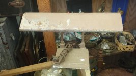
I found this little lamp a couple of weeks ago, and thought it was very cool. I didn't see a maker's mark on it anywhere, and today I finally found a similar lamp with a sticker barely hanging on at the bottom. Had similar qualities as mine, so I snapped a picture. Thank you research skills. It was the same manufacturer as mine. It's a drafting lamp. Without further yapping, here it is.....

My lamp...

attachment.php


Patents tied to this particular lamp with inventor renderings...
attachment.php

attachment.php

attachment.php

attachment.php

attachment.php

attachment.php

attachment.php


Nov. 16, 1954 l. 1. FlORl 2,694,535

ADJUSTABLE LOAD-CARRYING STRUCTURE Filed July e, 1950 7 Sheets-Sheet 1 111229 [.Fiorl Nov. 16, 1954 om 2,694,585

ADJUSTABLE LOAD-CARRYING STRUCTURE Filed July 6, 1950 7 Sheets- Sheet 2 Ira/era tor 37 I ruinglfiom' gigs.

Nov. 16, 1954 l. l. mom 2,694,585

ADJUSTABLE LOAD-CARRYING STRUCTURE I Filed July 6, 1950 7 Sheets-Sheet 3 in van tor ImgjglE i Nov. 16, 1954 l. FIORI ADJUSTABLE LOAD-CARRYING STRUCTURE 7 Sheets-Sheet 4 Filed July 6, 1950 Inventor Irl/LrjLHom' mlIIIII.

Nov. 16, 1954 1. FIORI 2,694,585

ADJUSTABLE LOAD-CARRYING STRUCTURE Filed July 6, 1950 7 Sheet s-Sheet 5 Inventor jruilqlfiori Nov. 16, 1954 l. FIORI 2,694,535

ADJUSTABLE LOAD-CARRYING STRUCTURE Filed July 6. 1950 7 Sheets-Sheet 7 Inventor fruirlql. F iori 2,694,585 Patented Nov. 16, 1954 ADJUSTABLE LOAD-CARRYING STRUCTURE Irving Idaco Flori, Chicago, 111., assignor to Art Specialty Co., tChicago, 111., a corporation of Illinois Application July 6, 1950, Serial No. 172,359

7 Claims. (Cl. 287-14) My invention relates to adjustable load-carrying support structures, and more in particular to such a support structure adapted to carry a fluorescent or like lamp to permit its ready adjustment to substantially any position.

In adjustable support structures of the character identitied, it is not only essential that adjustment be permitted to substantially any position, but also that such adjustment be maintained by a structure which permits a conductor to be run from a source of supply to the lamp without deleteriously affecting such conductors when the lamp is moved from position to position. In one form of structure, a single torsion spring is carried at the lowermost joint of the support structure, and the parts are so related to each other that the load as adjusted with respect to two hinged joints is counterbalanced by the single torsion spring. This structure has the advantage of leaving a substantially free opening for the conductors, but has the disadvantage that in some positions of the lamp counterbalancing is not completely effected by the single spring. In some structures, such as shown in Patent 2,233,300, an extra tube is provided solely for the purpose of passing the conductors around the two main joints which carry the counterbalancing torsion springs. In Fiori Patent 2,395,178 an improved structure was provided which permitted the conductors to pass through the two main joints, each of which was provided with a counterbalancing torsion spring, without injury to the conductors even after extensive use. While the said Fiori patent disclosed an adjustable support structure having definite advantages, it had certain drawbacks particularly when substantially the exact structure of the drawings was employed.

The principal object of the present invention is to improve the functioning of the herein identified Fiori structure while still retaining all of the desirable functional advantages thereof.

Another object is the provision of an improved structure of the Fiori type in which the friction provided at the separate joints remains unchanged even after extensive use.

Still another object is the provision of an adjustable support structure in which all of the functioning parts are completely enclosed, but in which they may be readily exposed for inspection or re-adjustment.

A further object is the provision of an adjustable support structure in which symmetry and desirable appearance may be maintained, and in which no fastening mechanism is visible when the structure is in use.

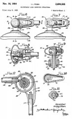
In the drawings in which a preferred embodiment of the invention is disclosed- Fig. l is a perspective view of the adjustable support structure, all of the structure above the lowermost housing member being rotated to the maximum extent in order to facilitate showing the relationship of the parts.

Fig. 2 is an enlarged fragmentary sectional view taken along the line 22 of Fig. 1 looking in the direction of the arrows, only a portion of the lamp housing being shown in section.

Fig. 3 is a bottom plan view looking along the line 3-3 of Fig. 2 in the direction of the arrows.

Fig. 4 is a transverse sectional view taken on the lin 44 of Fig. 2.

Fig. 5 is a fragmentary plan sectional view taken on the line 5-5 of Fig. 2.

Fig. 6 is an enlarged fragmentary elevational view showing the hinge joint of the adjustable load support which is nearest the lamp housing.

Fig. 7 is a view similar to Fig. 6, but with the joint housing cap removed.

8 is a sectional view taken on the line 88 of Fig. 9 is a vertical sectional view taken on the line 99 of Fig. 6.

Fig. 10 is an elevational View looking at the inside of the housing cap.

Fig. 11 is a transverse sectional view taken on the line 11l1 of Fig. 6 looking in the direction of the arrows.

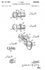
Figs. 12 and 13 are perspective views from opposite sides of the ring hinge member, forming a part of the joint shown in Fig. 6.

Fig. 14 is a perspective view of a bracket hinge member forming a part of the hinge joint shown in Fig. 6.

Fig. 15 is a perspective view of a friction and swivel member used in the joint of Fig. 6.

Fig. 16 is a perspective view showing a friction spring for controlling the friction in the hinge joint shown in Fig.

Fig. 17 is an enlarged sectional view taken along the line 1717 of Fig. 1 looking in the direction of the arrows, the figure thereby being a sectional View taken through the intermediate hinge joint of the adjustable support structure.

Fig. 18 is an enlarged elevational view of the hinge joint which is shown in Fig. 17.

Fig. 19 is a view similar to that in Fig. 18, but with the housing cap removed.

Fig. 20 is an irregular sectional view taken on the line 2020 of Fig. 18 looking in the direction of the arrows.

Fig. 21 is an irregular sectional view taken on the line 2121 of Fig. 18 looking in the direction of the arrows.

Fig. 22 is a perspective view showing the housing cap forming a part of the hinge joint of Fig. 18.

Fig. 23 is a perspective view of a friction bushing forming a part of the hinge joint of Fig. 18.

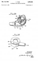
Fig. 24 is a perspective View of the bracket hinge member forming a part of the hinge joint of Fig. 18.

Fig. 25 is a perspective view of the ring hinge member forming a part of the hinge joint of Fig. 18.

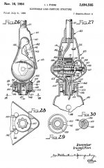
Fig. 26 is an enlarged sectional view, partly in elevation and partly broken away, the figure being taken generally along the line 2626 of Fig. 1.

Fig. 27 is a sectional view taken along the line 2727 of Fig. 26.

Fig. 28 is a fragmentary bottom plan view taken along the line 28-28 of Fig. 26 looking in the direction of the arrows.

Fig. 29 is a transverse sectional view taken along the line 29-29 of Fig. 26.

Fig. 30 is a sectional view taken along the line 3030 of Fig. 27.

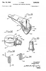
Fig. 31 is aperspective view of the bracket hinge member forming a part of the hinge joint shown in Fig. 26.

Fig. 32 is a perspective view of the ring hinge member forming a part of such joint.

Fig. 33 is a perspective view of a friction bushing employed in the hinge joint of Fig. 26.

Figs. 34 and 35 are torsion springs employed in the intermediate and lowermost hinge joints, respectively.

Referring now to the drawings, the adjustable support structure as shown therein comprises an upper tube 36 and a lower tube 37, the said tubes being connected by a hinge joint indicated generally by the reference character 38. The upper tube 36 is in turn connected to a lamp housing 39 by a hinge joint 41, and the said lamp housing 39 is supported to swivel with respect to said hinge joint 41. Similarly the bottom tube 37 is connected to a bottom housing 42 by a hinge joint 43, and there is a swivable connection between the housing 42 and the said hinge joint 43. The housing 42 maycarry suitable mechanism such as a power unit to supply luminescent tubes (not shown) supported in the lamp housing 39. The housing 42 may comprise part of a stand, or it may be provided with clamping mechanism 44 as indicated for attachment to a drawing table or the like.

The hinge joint 41 comprises a ring hinge member 46 (Figs. 12. 13) and a bracket hinge member 47 (Fig. 14). These two members are connected by means which will .be described, and the ring hinge member is swivelably connected to the lamp housing while the bracket hinge member is swivelably connected to the upper tube.36.
 

Attachments

  • 1.JPG
    1.JPG
    93.6 KB · Views: 103
  • 2.JPG
    2.JPG
    102.3 KB · Views: 103
  • 3.JPG
    3.JPG
    56.2 KB · Views: 103
  • 4.JPG
    4.JPG
    105.6 KB · Views: 103
  • 5.JPG
    5.JPG
    50.8 KB · Views: 103
  • 6.JPG
    6.JPG
    92.4 KB · Views: 101
  • 7.JPG
    7.JPG
    66.8 KB · Views: 100
Last edited:
To avoid these ads, REGISTER NOW!
OP
M

Mr_P

Well-known member
Joined
May 29, 2015
Messages
557
Location
Tinley Park, IL
Referring now first to the connection between the ring hinge member and the housing, this may be suitably generally similar to that shown in Fiori et al. Patent 2,476,850. A swivel bracket 48 is provided with a pair of lugs 49 which extend through holes in the metal comprising the housing 39, and the remaining portion of the bracket rests above such housing. The center portion of the swivel bracket is provided with a boss 51 into which a tubular portion 52 extends, said tubular portion also extending through an opening provided in housing 39. A flange 53 on the ring hinge member frictionally engages the top of the swivel bracket 48. To hold the ring hinge member in position, there is provided a leaf spring 54 and a bifurcated attachingplate 56. The ends of the leaf spring engage in recesses on a contiguous portion of the lugs 49, and-the bifurcated attaching plate engages in an annular groove 57 on the tubular portion of the ring hinge member. The bifurcated attaching plate also has an aperture which passes one of the lugs 49. The ring hinge member is thus swivelably mounted in position with continuous spring tension to provide friction of the flange 53 against the top of the swivel bracket. The swivel bracket is provided with an annular recess 58 which receives a lug 59 integral with the ring hinge member, and there is a stop 61 integral with the swivel bracket so that the housing 39 can be rotated through substantially 360 about the tubular portion 52 but it cannot be continuously rotated in one direction.

The bracket hinge member 47 isprovided with a housing portion 62 of irregular shape but having a ring portion 63 which extends within the ring portion 64 of the ring hinge member 46, the rim of said ring portion 64 riding on a shoulder 66. A post 67 is interiorly threaded to receive a fastening screw 68 which secures friction spring 69 against friction and swivel member 71 and holds the latter against the ring hinge member.

It will be noted, by referring particularly to Figs. 1215 inclusive, that one sideof the ring portion 64 is completely open but the other side is closed to form a web brokn only by the center opening 72. The friction and swivel member 71 has a slight embossment which engages in this center opening 72, and it also has a cutaway end portion which engages half way around the post 67; Thus the friction and swivel member 71 is held in against the ring hinge member and is prevented from turning by its engagement with the post 67. The ring portion 64 of the ring hinge member is thereby pinched between the shoulder 66 of the bracket hinge member 47 and the friction and swivel member 71. By controlling the position of the screw 68, the tension of the friction spring 69 can be controlled and thereby also the amount of friction restraining the hinge movement of the ring hinge member 46.

The bracket hinge member 47 is shaped at one end to receive the tube 36. The end of tube 36 has a side projection'73, and the tubular shaped end of bracket hinge member 47 is provided with a groove 74 to pass the projection 73 as the tube is inserted. Stops 76 are provided as shown in Fig. 2 against which the end of tube 36 engages; and when the tube 36 is rotated so that the projection 73 no longer is in alignment with the groove 74, the narrowed portion of the tube functions to provide a shoulder to prevent separation of the tube and hinge member 47. Normally the projection 72 is separated 180 from the groove 72, but sideways tilting of the lamp housing 39 is permitted so that there is a partial swiveling movement permitted around the tube 36. The edge of spring 69 limits swiveling movement in one direction by engaging the projection 73-, while a stop 77 integral with the bracket hin e member 47 limits the swiveling action in the other direction.

The hole through the ring portion 64 in alignment with the hollow inside of the tubular portion 52 (as shown particularly in Fi s. 8, 9, 13) provides means f r passin electrical conductors into the lamp housing 39. It will be noted that the conductors may *** from the upper tu e 36 around the post 67 into the housing portion 62. and then around the open side of the ring portion 64 and through the hole 78. The screw 68 may be t rned to adiust the friction without affectin" the p i i n of he wires in any way.

To complete the int fr m an a pear e st nd i and cover the adjusting screw 68, the cap 79 (shown in elevation in Fig. 10) is engaged over the joint in the manner shown particularly in Figs. 8 and 9. The cap 79 has a stud 81 in that portion of the cap which is dished the maximum extent to correspond to the major housing portion of the member 47. An attaching spring 82 is carried on the stud 81 and engages over the edge of the friction and swivel member "/1, the stud 81 extending through a hole near the edge of said member 71 to position the cap 79. An ear 83 engages in the narrowed end of the cap 79 to position such narrowed end and assist in supporting the cap 79 in position. it will be seen, however, that by engaging a sharp edge (as of a knife or screw driver) under the cap 79, it can be removed without affecting the adjustment of the joint in any way. And also that while the cap is in position, there is no possibility of tampering with the friction adjustment and affecting it adversely.

The intermediate hinge joint 38 is shown in detail in Figs. 17-25 inclusive. It comprises a bracket hinge member 84,- and a ring hinge member 86 which are frictionally hinged together and between which a torsion spring 87 (shown in Fig. 34) is supported as indicated particularly in Figs. 20 and 21. The bracket hinge member 84 is rigidly secured to the upper end of the bottom tube 37, and the ring hinge member 86 is also rigidly secured to the bottom end of tube 36, so that only a direct hinge action without any swiveling function is permitted at hinge joint 38.

The bracket hinge member 84 is provided with a rim 88, and ring portion 89 of the ring hinge member 86 engages over the said rim 88 and rests on a shoulder 91. Member 84 also has a housing portion 92 from which a tubular projection 93 extends, such tubular projection adapted to extend through a central opening 94 in the ring hinge member 86. A friction bushing 96 extends through the central opening 94 and into the tubular projection 93. Flange 97 on bushing 96 engages the web portion of the ring hinge member 86 around the edge of the central opening 94, and a lug 98 engages in an edge recess 99 on the tubular projection 93 to prevent relative turning movement of the bushing and tubular projection 93, while permitting such movement of the ring hinge member 86. A threaded stud 101 is carried by the bracket hinge member 84 centrally of the tubular projection 93; and an end opening 102 is provided in the friction bushing 96 through which such stud projects. A friction spring 103 is disposed within the friction bushing 96 and around the stud 101 so that a nut 104 on the said stud will compress the said spring and control the friction with which the ring hinge member 86 is supported between the shoulder 91 and the flange 97 of the friction bushing.

The torsion spring 87, as shown in Fig. 34, is disposed between the tubular projection 93 and the ring portion 89, with one end 106' extending into a hole 107 on the web portion of the ring hinge member, and the other end 108 engaged behind one of a number of projections 109 at the base of the tubular projection 93. The torsion spring 87 is thus preliminarily tensioned and supported in such manner that relative movement f the hinge members increases the tension of the torsion spring as required for counterbalancing the suspended load of the housing 39.

A housing cap 111 has a central stud 112 which carries a retaining. spring 113 and is also apertured to receive the end of the threaded stud 101. In this position a free formed end of the spring engages over a lipped projection 114, forming a part of the bushing 96. A pair of lugs 116 on the cap 111 project into the body of member 86 to prevent cap 111 rotating about the threaded stud 101. The cap 111, however, may easily be removed with a suitable tool such as a screw driver by merely lifting it.

In the construction shown, the conductors may pass the hinged joint either through the housing portion 92 or through the cap 111. It will be seen that b th the members 84 and 86 are so constr cted that conductors passing through the tubes 36 and 37 may be led directly into the joint portion, the member 84 being provided with a tubular passageway leading to a recessedportion 118 f rmin a' rt of the housing 92, and the member 86 being provided with a tubular passa eway 119 leading t the center of the ring rtion 89. The central o ening 94 is provided wi h an offset and conductors passing through the tubular passageway 119 may pass through the offset portion 95 into the cap 111, around the threaded stud 101, and into the tubular passageway 117. The conductors may also pass through the tubular passageway 119, into the housing portion 92, around the tubular projection 93, then through the recessed portion 118 and into the tubular passageway 117.

The lower hinge joint 43 comprises a bracket hinge member 121 and a ring hinge member 122. The bracket hinge member 121 has a housing portion 123 with a rim 124, and beneath the rim a shoulder 126. A threaded stud 12-7 projects upwardly from the center of a boss 128 which is integral with the member 121 and is disposed centrally of the main portion of the housing portion 123. The ring hinge member 122 is provided with a downwardly extending tubular portion 129 (which will be referred to hereinbelow), and an integral ring portion 131, the edge of which engages against the shoulder 126 when the ring portion 131 is fitted over the rim 124. A friction bushing 132 extends through a central opening 133 in the web portion of the ring 131 and down over the boss 128. A ridge 134 extends into a groove 136 in the bushing 132 to prevent the bushing turning around the boss. The bushing 132 has a flange 137 which engages the web portion of the member 122 around the edges of the central opening 133. A friction spring 138 is disposed within the bushing 132, with one end engaging against an inner shoulder of the said bushing so that when a nut 139 is tightened the bushing is forced in a direction to clamp the ring hinge member.

The bracket hinge member 121 also has a recessed portion 141 which comprises a continuation of the housing portion 123. A ridge 142 projecting into the recessed portion 141 acts as a stop for one end 143 of a torsion spring 144, the other end 146 of which extendsdown into the tubular portion 129 of the ring hinge member 131. The spring 138 is also so constructed and arranged that its torsion is increased with increase of the overhanging load so that there is an automatic counterbalancing effect.

The hinge joint 43 is also provided with a housing cap 147 having an apertured stud 148 which receives the free end of stud 127 and also supports a retaining spring 149, the latter engaging over a lipped projection 151 from the bushing 132. Projections 152 assist in positioning the cap 147.

The tubular portion 129 of the ring hinge member 122 extends down into a protuberance 153 on the lower housing 42 which is shaped to support the entire structure. A flange 154 above the tubular portion 129 and integral with the ring hinge member 122 engages the top edge of the protuberance 153. A leaf spring 156 extends around the tubular portion 129; and a crenulated washer 157 engages behind a shoulder formed by an annular recess 158 to hold the parts in assembled relation and maintain tension on the leaf spring 156. It will be noted, particularly by reference to Figs. 26 and 28, that the ends of the leaf spring engage lugs 160 on the underside of the housing in such manner as to be held in position.

The lower housing 42 is adapted to carry a transformer or other power unit, and commercial power lines are adapted to enter the housing through a suitable opening 159. Conductors lead from the power unit (not shown) and extend up through the tubular portion 129 to the interior of the hinge joint 43. The conductors here preferably run through the housing portion 123 of the bracket hinge member 121, thence around the bushing 132 through the recessed portion 141, and into the bottom end of tube 37. They may, however, extend from the tubular portion 129 through the olfset portion 135 of the central opening 133 (note Fig. 35) into the space below the cap 147 and then into the tube 37.

It will be apparent that while each of the joints 38, 41 and 43 differs from the others in minor respects because of its position, nevertheless all of the joints have basically the same combination of parts. In each instance there is a bracket hinge member; a ring hinge member: resi ient means. including a clamping member, for holding the two said hinge members together; and a can with a retaining spring clamped to the clamping member to hold the cap over the assembly comprising the clamping member. In each of the joints also the bracket hinge mem er forms a housin and the springheld can forms in etfect a continuation of the housing. In each instance ample pr vision is made for the conduct rs. In the upper joint 41 the conductors pass from the tube 36 into the tubular portion 52 through the housing portion 62; while in the other two joints the conductors may either pass through the housing portion or through the cap portion, in the latter case the conductors passing out through the offset portion or as the case may be.

What I claim as new and desire to protect by Letters Patent of the United States is:

1. In an adjustable support member, a hinged joint comprising a ring hinge member having an annular ring portion open at one side and provided with a centrally apertured web at the other side, a bracket hinge member having a housing portion provided with an annular shoulder receiving the open side of the annular ring portion, a friction clamping member extending into the aperture of the web for centering the same with respect to the web and provided with a flange engaging the outer face of the web, means interconnecting the bracket hinge member and the friction clamping member to prevent relative rotation therebetween, a screw threaded member carried by and extending from the bracket hinge member and having a shoulder thereon beyond the friction clamping member, a spring interposed between the shoulder of the screw threaded member and the friction clamping member adjustably frictionally clamping the ring hinge member between the bracket hinge member and the friction clamping member, a cap slidably engaging the ring portion of the ring hinge member adjacent the web thereof and also engaging the bracket hinge member and covering the friction clamping member, screw threaded member and spring and forming in appearance a uniform continuation of the housing portion of the bracket hinge member, and means including a spring clip internally carried by the cap removably securing the cap in place.

2. In an adjustable support member, a hinged joint comprising a ring hinge member having an annular ring portion open at one side and provided with a centrally apertured web at the other side, a bracket hinge member having a housing portion provided with an annular shoulder receiving the open side of the annular ring portion, a friction clamping member extending into the to the web and provided with a flange engagnig the outer face of the web, means interconnecting the bracket hinge to the web and provided with a flange engaging the outer member and the friction clamping member to prevent relative rotation therebetween, a screw threaded member carried by and extending from the bracket hinge member and having a shoulder thereon beyond the friction clamping member, a spring interposed between the shoulder of the screw threaded member and the friction clamping member adjustably frictionally clamping the ring hinge member between the bracket hinge member and the friction clamping member, a cap slidably engaging the ring portion of the ring hinge member adjacent the web thereon and also engaging the bracket hinge member and covering the friction clamping member, screw threaded member and spring and forming in appearance a uniform continuation of the housing portion of the bracket hinge member, a lipped projection on the friction clamping member, and a spring clip internally carried by the cap and engaging over the lipped projection for removably securing the cap in place.

3. In an adjustable support member, a hinged joint comprising a ring hinge member having an annular ring portion open at one side and provided with a centrally apertured web at the other side, a bracket hinge member having a housing portion provided with an annular shoulder receiving the open side of the annular ring portion, a friction clamping member in the form of a bushing extending into the aperture of the web for centering the same with respect to the web and provided at one end with a flange engaging the outer face of the web and with an internal shoulder at its other end, means interconnecting the bracket hinge member and the friction clamping member to prevent relative rotation therebetween, a threaded post carried by the bracket hinge member and projecting through the friction clamping member, a nut adjustably threaded on said post, a compression spring disposed within said friction clamping member about said post and engaging the nut and the internal shoulder of the friction clamping member adjustably frictionally clamping the ring hinge member between the bracket hinge member and the friction clamping member, a cap slidably engaging the ring portion of the ring hinge member-adjacent the web thereof and also engaging the bracket hinge member and covering the friction clamping member, post, nut and spring and forming in appearance a uniform continuation of the housing portion of the bracket hinge member, and means including a spring clip internally carried by the cap removably securing the cap in place.

4. In an adjustable support member, a hinged joint comprising a ring hinge member having an annular ring portion open at one side and provided with a centrally apertured web at the other side, a bracket hinge member having a housing portion provided with an annular shoulder receiving the open side of the annular ring portion, a friction clamping member extending into the aperture of the web for centering the same with respect to the web and provided with a flange engaging the outer face of the web, means interconnecting the bracket hinge member and the friction clamping member to prevent relative rotation there between, a post projecting from the bracket hinge member adjacent the ring portion of the ring hinge member, a leaf spring engaging the friction clamping member and overlying the end of the post, a screw adjustably threaded in said post and extending through and engaging the leaf spring and adjustably frictionally clamping the ring hinge member between the bracket hinge member and the friction clamping member, a cap slidably engaging the ring portion of the ring hinge member adjacent the web thereof and also engaging the bracket hinge member and covering the friction clamping member, post, screw and spring and forming in appearance a uniform continuation of the housing portion of the bracket hinge member, and means including a spring clip internally carried by the cap removably securing the cap in place.
 
OP
M

Mr_P

Well-known member
Joined
May 29, 2015
Messages
557
Location
Tinley Park, IL
5. In an adjustable support member, a hinged joint comprising a ring hinge member having an annular ring portion open at one side and provided with a centrally apertured web at the other side, a bracket hinge member having a housing portion provided with an annular shoulder receiving the open side of the annular ring portion and a tubular projection concentric with the annular shoulder, a torsion spring surrounding the tubular projection with one end in engagement with the ring hinge member and the other end in engagement with the bracket hinge member, a friction clamping member in the form of a bushing located within the tubular projection and extending into the aperture of the web for centering the same with respect to the web and provided at one end with a flange engaging the outer surface of the web and with an internal shoulder at its other end, means interconnecting the tubular projection and the friction clamping member to prevent relative rotation therebetween, a threaded post carried by the bracket hinge member and projecting through the friction clamping member, a nut adjustably threaded on said post, a compression spring disposed within said friction clamping member about said post and engaging the nut and the internal shoulder of the friction clamping member adjustably frictionally clamping the ring hinge member between the bracket hinge member and the friction clamping member, a cap slidably engaging the ring portion of the ring hinge member adjacent the web thereof and also engaging the bracket hinge member and covering the friction clamping member, post, nut and spring and forming in appearance a uniform continuation of the housing portion of the bracket hinge member, and means including a spring clip internally carried by the cap removably seportion open at one side and provided with a centrally apertured web at the other side, a bracket hinge member having a housing portion provided with an annular shoulder receiving the open side of the annular ring portion and a boss concentric with the annular shoulder, a friction clamping member in the form of a bushing extending into the aperture of the Web and provided at one end with a flange engaging the outer face of the web and with an internal shoulder at its other end, said friction clamping member having a groove receiving a projection on the boss to prevent relative rotation between the friction clamping member and the bracket hinge member, a threaded post carried by the boss andprojecting through the friction clamping member, a nut adjustably threaded on said post, a compression spring disposed within said friction clamping member about said post and engaging the nut and the internal shoulder of the friction clamping member adjustably frictionally clamping the ring hinge member between the bracket hinge member and the friction clamping member, a cap slidably engaging the ring portion of the ring hinge member adjacent the web thereof and also engaging the bracket hinge member and covering the friction clamping member, post, nut and spring and forming in appearance a uniform continuation of the housing portion of the bracket hinge member, and means including a spring clip internally carried by the cap removably securing the cap in place.

7. In an adjustable support member, a hinged joint comprising a ring hinge member having an annular ring portion open at one side and provided with a centrally apertured web at the other side, a bracket hinge member having a housing portion provided with an annular shoulder receiving the open side of the annular ring portion, a friction clamping member in thefor'm of a bushing extending into the aperture of the web for centering the same with respect to the web and provided at one end with a flange engaging the outer face of the web'and with an internal shoulder at its other end, means interconnecting the bracket hinge member and the friction clamping member to prevent relative rotation therebetween, a threaded post carried by the bracket hinge member and projecting through the friction clamping member, a nut adjustably threaded on said post, a compression spring disposed Within said friction clamping'member about said'post and engaging the nut and the internal shoulder of the friction clamping member adjustably frictionall'y clamping the ring hinge member between the bracket hinge member and the friction clamping member, a cap having a socket receiving the end of the post and slidably engaging the ring portion of the ring hinge member adjacent the web thereof and also engagingthe bracket hinge member and covering thefriction clamping member, post, nut and spring and forming in appearance a uniform continuation of the housing portion of the bracket hinge member, a lipped projection on the friction clamping member, and a spring clip internally carried by the cap and engaging over the lipped projection for removably securing the cap in place.

References Cited in the file of this patent UNITED STATES PATENTS Number Name Date 1,391,692 Pugh Sept. 27, 1921 1,899,555 Campbell Feb. 28, 1933 2,395,178 Fiori Feb. 19, 1946
 
To avoid these ads, REGISTER NOW!

JackDiddly

Well-known member
Joined
Oct 6, 2014
Messages
185
Location
SE WI
I picked up one a few years back... You certainly did your homework!:beer:
If you could re-size the photos a bit that would help. Its currently like looking at a microfiche.
 

notlob

Well-known member
Joined
Aug 19, 2013
Messages
1,384
Location
norcal
Please repost with more details in larger font and with larger pictures.

:needpics:
 

lauver

Well-known member
Joined
Nov 11, 2007
Messages
1,433
Location
Belton, TX
Mr_P,

I've got an Art Specialty Company single tube lamp sitting on my desk. I bought it used about 1976 or 1977. Rock solid and no problems with it all these years.
 
OP
M

Mr_P

Well-known member
Joined
May 29, 2015
Messages
557
Location
Tinley Park, IL
This is the one I seen at the flea market, but they were asking like $38 in that condition. It must have sat outside for too long. Shame. I'm sure a coat of paint might help it last another 65 years.

attachment.php
 

Attachments

  • 20170508_131231.jpg
    20170508_131231.jpg
    140.3 KB · Views: 55
To avoid these ads, REGISTER NOW!
Top Bottom