To avoid these ads, REGISTER NOW!

Atlas FM9SL Scissor Lift Flush-Mount Install

jtbinvalrico

Well-known member
Joined
Jan 2, 2010
Messages
1,375
Location
Tampa FL
*Fast forward almost a year and a half.....Here's what it looks like done and lifting my F150 Super Crew. I look forward to updating this photo with a 66 Mustang. :beer:

**Fast forward some more.....That hunt for a 65-66 Mustang sent me to Chicago to fetch this 69. Yeah, buddy!

1.jpg
1.jpg

************************************************************************
I've been asked to put some key details up top here so they're easier to find....good suggestion. Here's some key data, measurements, specs, and notes that you'll find referenced in the ensuing year and a half build:

- Finished depth 14"
- Excavated depth 27"
- Finished length 66"
- Excavated length 76"
- Finished width 23"
- Excavated width 33"
- ALWAYS MEASURE YOUR ACTUAL PLATFORMS IF AT ALL POSSIBLE.....My platforms are
exactly 64 5/8" x 21 5/8"......not the 64 1/2" x 21 1/2" indicated in the literature. That
extra 1/8" all around got lost in form variances, concrete expanding, etc. Consider this in
your plans.
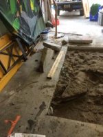
- 4" of compacted #57 stone base; I used 3/4 yard of stone.
- 9" concrete base
- 5" walls all around
- I ended up with a 1/2" to 5/8" gap between the platforms and the finished walls.
- I set my platforms at 31" apart.
- My garage is 19.5 feet deep from closed garage door to the wall at the front of the
garage.
- The front edge of the installed platform is 85.5" from the front wall of the garage.
- The rear edge of the installed platform is 84" from the closed garage door.
- I can fit and lift a 2005 F150 Lariat Super Crew high enough to walk under. The front and
rear bumpers are mere inches from the front wall and garage door. This truck is 223" in
length. My ceiling is a shade under 12 feet. With an old Mustang on the lift, I'd have about
4 feet of space to divide between the front and back to work on. I'm not pulling an
engine...but it's plenty for maintenance work.
- Forms were built with 3/4"marine grade plywood. No form release was used.
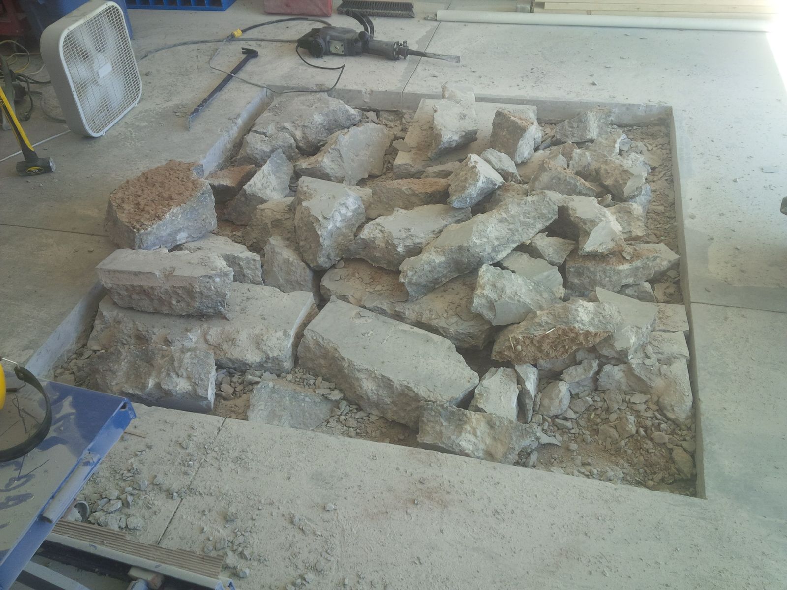
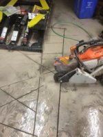
- I used a 16" Husqvarna Varicut blade on an 18" gas saw with water to cut the slab.
- 260 feet of #4 rebar was doweled 5 3/4" into the existing slab.
- 3 to 4 tubes of PC Concrete epoxy were used to set the doweled rebar in 40 total holes.
- A 10mil vapor barrier was used....1000sf for $80.00
- 3" PVC was used for the hose runs.
- 1" x 1/8" angle iron was used for the edging.
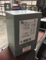
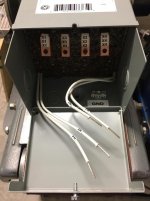
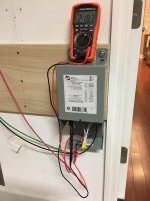
- A Hammond Q1C0ESCB transformer was used to buck my 248-250v down to the 209-
231v recommended by GSE.
- My upgraded hoses are ContiTech and are longer to allow the control panel to be set
farther away.
- I used AW-32 hydraulic oil.
- Vonberg velocity fuses were ordered directly from Vonberg; total cost was about $55.00.
- I put a Vonberg 28001-804-3.50 velocity fuse on the master cylinder.
- I put a Vonberg 28001-804-2.75 velocity fuse on the slave cylinder.
- I used 1/4-4F40HG5S Parker port adapters to adapt the 1/4 BSPP port to the fuses.
The adapters $50.00 for both and were ordered at my local Parker-Goodyear store.
- I did not use the included anchors. I drilled all the way through the 9" base and used
galvanized 5/8" anchors.
- Make sure you are not dealing with a post-tensioned slab.
- Make sure you locate all pipes under your slab....I nearly pierced an unexpected water
line, and that was after having lines located and marked.

- Here's the locking heights. These measurements are from the garage floor to the top of
the platform, rounded to the nearest .25". You can also see a variance based on how
deep your pits are, 13-14". Remember to account for any riser blocks you'd use:

Starting from the lowest:

4"
11"
16.5"
22"
26.75"
31"
35.5"
39.75"
44"
48"
52"
55.75"
59.5"
63.5"
67"
71"......This is the highest point where you get full tooth engagement. You could go higher, but the locking teeth wouldn't be fully interconnected.
************************************************************************
If you have a few hours to spend, read on....

I watched with great interest the in-floor scissor lift install, group buys, and troubleshooting detailed in this fantastic thread: https://www.garagejournal.com/forum/showthread.php?t=35433

Unfortunately, many of the pictures were ruined in the PB debacle. It’s still a wealth of info and is a primary resource. My lucky day has come.
DE9417E3-C0F8-4074-A1DD-EBB8648BE404.jpg
I drove over to east Tampa today and picked up my Atlas FM9SL. It’s a 9000 lb capacity scissor lift meant to be flush mounted into the floor. I’m taking a ton of photos from beginning to end, and I want to show some workarounds and problem solving that might help the average suburban shadetree like me. I want to answer a lot of the dumb questions I had/have along the way. If you don’t have a forklift, skid steer, bobcat, gantry crane, or even an engine hoist, you can do this with some floor jacks, a small hand winch, a healthy respect for the laws of physics....and mostly by yourself if necessary (except the concrete). I can turn a wrench and break things; jack (amateur) of many trades and definitely master of none....but, we’re all willing to try. I’m going to include actual costs and account for time spent on the various steps of the process.

Step 1: Is this feasible? I have a standard 3 car attached garage. It’s not deep...maybe 19.5 feet. Actually, that *****. It means that when I want to lift my 05 Lariat, I’ll have to scurry under it to work with 6” clearance front and rear. Brakes and rotations are easier, but long-term?....truth is, the truck is getting on in miles and years and isn’t in my long term plans. A 1966 Mustang is, maybe a 71 Vette. Those are a fit with a few feet at the front to work. So, yes. It’s feasible and compatible with my future plans.

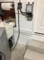
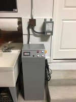
Are electrical and air in place? Recently completed my subpanel. We have power and air.

Height. Lucky me. Ceiling is a shade under 12 feet. With the mini-split keeping the shop at a comfy 76, the garage door stays closed, and lifted cars fit right between the standard lift motor and door tracks on one side of a double bay.

What’s under the garage floor? I paid about $300 to have a guy come out with some pinging radar deal to find the pipe I knew was somewhere under that floor. Good news is that it’s under the far bay the wife parks in, and my center bay is clear.
BB2D23C5-16E1-47E8-84F9-A5EB9C915B99.jpg
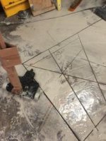
Step 2: Measuring. Blue tape...More measuring....One thing I learned in the above-referenced epic thread is this: Have the lift on site before cutting. So after all the calculations and figuring center of balance for vehicles I have and don’t yet have, I reached the point where the numbers had to get real. There’s just too much variance in some of these things to guess and hope. So they’re here now and can be measured accordingly. Then there’s width....31” seems to be the agreed upon figure.

Step 3: Ordered from Greg Smith. Lift was $3545, I got the cross bars as well (never know what you’ll end up lifting) $350....With tax, about $4000 delivered to the Estes terminal. U-Haul trailer was $40.
B183D9B4-3427-4D30-A255-D7A13A506289.jpg

Next, unloading. Solo.
 
Last edited:
To avoid these ads, REGISTER NOW!
OP
J

jtbinvalrico

Well-known member
Joined
Jan 2, 2010
Messages
1,375
Location
Tampa FL
Step 4: That forklift made the loading look easy....No forklift at home. My plan was to back the trailer up to the garage and winch the lifts off. They’d drop one end first onto the HF dollies I had, then I’d lower the remaining end onto the second dolly with a floor jack. I’ll just drop a string of pictures to tell the story. I will note two things first: 1) Yes, that little lag bolt held the winch just fine, and 2) The lifts aren’t evenly balanced for weight....meaning they might tip off center quicker than you think...
IMG_2463.JPGIMG_2525.JPGIMG_2487.JPGIMG_2495.JPGIMG_2500.JPGIMG_2501.JPG


Sent from my iPhone using Tapatalk
 
Last edited:
OP
J

jtbinvalrico

Well-known member
Joined
Jan 2, 2010
Messages
1,375
Location
Tampa FL
IMG_2502.JPGIMG_2503.JPGIMG_2506.JPGIMG_2507.JPGIMG_2508.JPGIMG_2509.JPG

The lift is pulled until it just begins to tip, then a light push with the hand guides it down to the dolly.
IMG_2510.JPG


Sent from my iPhone using Tapatalk
 
OP
J

jtbinvalrico

Well-known member
Joined
Jan 2, 2010
Messages
1,375
Location
Tampa FL
Lift the other end off the trailer with the floor jack, roll the trailer forward, lower the remaining end onto the other dolly, and done. Repeat for the other side.

IMG_2512.JPGIMG_2514.JPGIMG_2515.JPGIMG_2529.JPG

Up next, taking exact measurements, marking the floor, getting ready to cut, and welding up the metal concrete edging.


Sent from my iPhone using Tapatalk
 

KDubU

Member
Joined
Dec 30, 2017
Messages
18
Location
Kennebunk, Maine
Very cool. Can you explain what you're planning with the floor? I am assuming you are cutting it but what else needs to done?
 
OP
J

jtbinvalrico

Well-known member
Joined
Jan 2, 2010
Messages
1,375
Location
Tampa FL
I'm jealous!

I bet the pucker factor was high when the lift was teetering on the edge of the trailer.


I tried using the drill attached to the winch after I got the lift up on some slick pieces of PVC to clear the pallet. I had tied the end of the pallet to the trailer to stop it from moving with the lift. After coming off the end of the pallet and resting on the end of the trailer, I had to get it moving again. Part of my physics lesson was to be reminded that heavy things in motion like to stay in motion. The tipping point came a bit early because it seemed the lift was slightly heavier on one end. No harm done. I just realized it’s better to slowly winch it off with the ratchet....winch, check, winch, check...tip.

Nice work!

Which u-haul trailer did you use?

Looks to be the 6 x 12 with dual axle.


Exactly. You can get this trailer in two flavors: tailgate ramp or not. For me, the ramp would have hindered pulling the lift to the end and tipping it.

Very cool. Can you explain what you're planning with the floor? I am assuming you are cutting it but what else needs to done?


They’re going to be recessed, as seen in this photo of someone else’s install:
View attachment 738167

Next steps:

- Take some detailed photos and measurements. Members often have questions about the insides of the control box and want an up close look at the mechanics and build quality.

- Determine final placement and confirm measurements to be marked out on the floor.

- Determine my incoming voltage and acquire the appropriate buck/boost transformer.

- I’m certain I’ll need longer hydraulic lines....have to get those made up.

- Connect everything and do a function check (everything in the manual short of lifting a vehicle).

- Hang plastic around the cutting area; lay out plastic and an edge to contain the concrete cutting mess.

- Rent the walk-behind gas powered concrete saw. Cut perimeters and section accordingly.

- Rent the jackhammer; breakup concrete. A trip to the dump.

- Dig out dirt. Dispose.

- Run PVC lines to route hydraulic and air lines.

- Rent compactor; compact pits.

- Go sit down with the concrete guy. I’ve identified a local outfit that does small jobs. They have these miniature mixer trucks that do up to 2 yds and appear to be based on a dually pickup chassis. I’m willing to pay extra for a couple skilled guys who can place and finish the concrete....I’d assist them as needed.

- Bend rebar, drill and epoxy the rebar to the slab....Follow whatever advice the concrete guy gave.

- Build the forms.

- Fabricate and weld out of 1.5” angle steel frames for pit edges. Attach to forms.

- Set forms. Concrete pour.

- Remaining install after concrete cures.


Sent from my iPhone using Tapatalk
 

ItsNemo

Well-known member
Joined
Mar 5, 2016
Messages
4,805
Location
Canada
Sounds like you've got things pretty sorted out. I did my flush mount Bendpak a couple years ago and it was a fun project.

Don't underestimate how much material you're going to need to remove, might be more than one trailer full.

Also, consider buying the jack hammer; a clone TR Industrial (or similar) isn't very expensive and actually work pretty well.
 
OP
J

jtbinvalrico

Well-known member
Joined
Jan 2, 2010
Messages
1,375
Location
Tampa FL
Sounds like you've got things pretty sorted out. I did my flush mount Bendpak a couple years ago and it was a fun project.

Don't underestimate how much material you're going to need to remove, might be more than one trailer full.

Also, consider buying the jack hammer; a clone TR Industrial (or similar) isn't very expensive and actually work pretty well.


I’m anticipating many trips to the dump. Space is at such a premium, wife needs to be able to park in her bay, and I just have no place to store anything outside - HOA suburbia - as things come out of the ground, they go in the truck to the dump.....I’m pulling about 2200 lbs of concrete out. That’s at least 4 truck loads in my F150 unless I rent a trailer....and on it goes. Logistics!.....Almost all of the in and out and construction all has to occur in the same space.

Buying the jack hammer would be great if I had space for it later....no room to keep it.

Rent, use, dump, rent, use, dump....LOL. Presently looking at a 6 month time to completion.


Sent from my iPhone using Tapatalk
 

Keith_MN

Well-known member
Joined
Dec 13, 2009
Messages
137
Location
Minneapolis Metro
I am subscribing to get the updates on this project.

I know that front to back placement is going to be critical for you in your garage. At some point, can you share how you calculated these dimensions?

Thanks,
Keith
 

ItsNemo

Well-known member
Joined
Mar 5, 2016
Messages
4,805
Location
Canada
I’m anticipating many trips to the dump. Space is at such a premium, wife needs to be able to park in her bay, and I just have no place to store anything outside - HOA suburbia - as things come out of the ground, they go in the truck to the dump.....I’m pulling about 2200 lbs of concrete out. That’s at least 4 truck loads in my F150 unless I rent a trailer....and on it goes. Logistics!.....Almost all of the in and out and construction all has to occur in the same space.

Buying the jack hammer would be great if I had space for it later....no room to keep it.

Rent, use, dump, rent, use, dump....LOL. Presently looking at a 6 month time to completion.


Sent from my iPhone using Tapatalk
They're not that big...buy it for the job and sell it when you're done. If you have to rent for a few days, it's going to cost more. Best part about buying is you can work on your own schedule.

Here's what mine did, nice big chunks:

Floor1.jpg
 

gerryw

Well-known member
Joined
Aug 10, 2008
Messages
815
Location
toronto area
When i did my recessed lift, i skipped the jackhammer, just did a ton of cuts (smaller pieces) and use a prybar(4’) to get them out, easier on ears/back.
I use (and can borrow) a jackhammer @work and i still skipped using it.
I used a Stihl on a trolley(again from work)

Gerry
 

Attachments

  • 74801A55-B01F-47F5-87F0-BEE8085EF5F2.jpg
    74801A55-B01F-47F5-87F0-BEE8085EF5F2.jpg
    12.9 KB · Views: 806
  • BBFAED43-977C-4226-B0CE-9E3D6D64B8FA.jpg
    BBFAED43-977C-4226-B0CE-9E3D6D64B8FA.jpg
    13.8 KB · Views: 749
  • 217DD18A-6F54-4B7A-BBEE-9B44CB314E77.jpg
    217DD18A-6F54-4B7A-BBEE-9B44CB314E77.jpg
    13.3 KB · Views: 792
Last edited:

gerryw

Well-known member
Joined
Aug 10, 2008
Messages
815
Location
toronto area
BTW, to unload my scissor lift (it was on a skid) i hooked a chain to lift, hooked chain to a bar across my open back door, then my wife drove the trailer forward lol.

Gerry
 

ItsNemo

Well-known member
Joined
Mar 5, 2016
Messages
4,805
Location
Canada
When i did my recessed lift, i skipped the jackhammer, just did a ton of cuts (smaller pieces) and use a prybar(4’) to get them out, easier on ears/back.
I use (and can borrow) a jackhammer @work and i still skipped using it.
I used a Stihl on a trolley(again from work)

Gerry
That only works if the slab isn't too thick...I was going through 6 inches so the typical 14" saws didn't have enough depth (usually only good for 4-4.5").
 

gerryw

Well-known member
Joined
Aug 10, 2008
Messages
815
Location
toronto area
That only works if the slab isn't too thick...I was going through 6 inches so the typical 14" saws didn't have enough depth (usually only good for 4-4.5").

Ok, gotcha.
On my floor i did a pilot hole and used a small rod to measure,
my floor was 3-1/2”

Gerry
 
Last edited:
To avoid these ads, REGISTER NOW!
OP
J

jtbinvalrico

Well-known member
Joined
Jan 2, 2010
Messages
1,375
Location
Tampa FL
You live on the Gulf Coast like I do. Will the water table level have an impact on the installation?
They’ve elevated our neighborhood more than a few feet to follow some sort of flood compliance rules. I’ll be no more than about 2 feet into the ground here. Even if we were lower I wouldn’t worry about it.
I know that front to back placement is going to be critical for you in your garage. At some point, can you share how you calculated these dimensions?

Thanks,
Keith
I’m installing this lift with an eye about 2-3 years in the future. My daily is a F150 Supercrew. If I intended to keep or drive something that size forever, I’d need to reconsider some things, and perhaps consider a diagonal installation - which would encroach on the activities of the bays on either side of my lift bay.

The F150 is temporary. Nonetheless, I’m factoring it into lift placement because, why not. I believe I’ve got the shallowest standard 3 car garage going, and that’s part of why I’m sharing all this. It’s reality for many of us in the ‘burbs.

What’s coming? I’ve got my eye on a 65-66 Mustang, maybe a 68-72 Vette. Other cars likely to make it on the lift: A Nissan Versa and the wife’s Jaguar XE. By considering the most ridiculously cramped vehicle in my plans (ye olde F150) I’m covering all bases.

I offer up my plans and research both to enlighten and to get advice....please chime in.

I cleared the center bay and lined up the truck. I ended up with maybe six inches clearance in the front and in the back with the door closed. There’s a clear shot to the ceiling between the lift motor and garage track. If I opened the door, I could get it off the ground for tire rotations, brakes, etc....which would involve scurrying in and out of the adjacent single garage door.
IMG_2627.jpg
IMG_2626.jpg
This exercise had two goals: 1) to aid in lift placement, and 2) to determine the center of mass for the truck. I put floor jacks on either side frame rail of the truck and lifted it off the ground at its center point. Before all this I had done some calculations to determine the center of mass of the truck....I’m no engineer, but I ended up fairly close in my math. I’m seeking this data for that Mustang and Vette as well.
IMG_2705.jpg
My math had the CM at the center of the front door handle. It ended up being at about the B pillar. I lifted both sides til it balanced off all four wheels and marked everything with blue tape:
IMG_2637.jpg
IMG_2638.jpg
I marked on the floor the locations of bumpers, wheels, and spans of rocker panels:
IMG_2640.jpg
IMG_2643.jpg
......continued.


Sent from my iPhone using Tapatalk
 
OP
J

jtbinvalrico

Well-known member
Joined
Jan 2, 2010
Messages
1,375
Location
Tampa FL
Why all the fuss over center of mass? With a smaller car, you locate it on the lift based on CM and that’s that. But if you’ve pushed the limits and have little to no room front and rear, you need this info because the front wall is non- negotiable....good thing the truck is short term.

With tape all over the floor, I backed the truck out and started measuring. Looking at these lift platforms one would think center is center....but is that really so? As it lifts, the “center line” where all the bolts are and the scissor arms meets moves forward relative to the overall length of the platform. I compared the manuals with actual measurements I was taking. Wait, did I say manual(s)? Check out the two manuals included with the lift. Note that one version has only one extension, while the other (the one I have) has two, front and back:
IMG_2689.jpg
The correct manual seems to have been gone over, tho the translation is still bad, and it sports measurements in inches, not mm.

I needed that accurate picture to try to identify where center would be at full lift....(I guess I’ll confirm this when I test fire it).
IMG_2706.jpg
IMG_2701.jpg
Blue tape marks center on the floor and what I believe will be on the platform at full lift. With all this, I began to slide things around with a 31” spacing between platforms. Tape shows the platforms within the rocker panel markings for the truck.

This is all good and well, but it’s just an informative exercise. Is optimum placement based on the truck the best thing overall? Am I sacrificing room at the front of that Mustang for the sake of placing this truck? I’ll do a similar exercise with some other vehicles to optimize it....we’re still a ways off from cutting, so there’s plenty of leeway here.

I need to get ready to test the lift. They move quite easily on the four dollys. I need to consider and account for any “tippiness” that may occur as they are tested while sitting on their dollys.

I’ve ordered a transformer to buck the voltage from a measured 248-250 down to 220 as recommended by Greg Smith. My question about these transformers sparked a debate in the electrical forum. Some say it’s not necessary because the duty cycle here is so short. I don’t mind the $175 to avoid any problems, real or theoretical. The point was made, however, that you want to be careful about not bucking it too low, as low voltage can harm the motor. I measured voltage at different times and sized the transformer to get me right in the middle of the recommended 209-231 volts. Beyond that, no one articulated any real harm that using one would cause, aside from the dent in your wallet.


Sent from my iPhone using Tapatalk
 
OP
J

jtbinvalrico

Well-known member
Joined
Jan 2, 2010
Messages
1,375
Location
Tampa FL
Here’s some pictures of platforms and the inside of the control box:
IMG_2656.jpg
IMG_2662.jpg
IMG_2668.jpg
IMG_2670.jpg
IMG_2671.jpg
IMG_2672.jpgIMG_2690.jpg


Sent from my iPhone using Tapatalk
 

Stryker124

Well-known member
Joined
Aug 19, 2005
Messages
93
Location
N.E. Ohio
Thank you for the step by step! I look forward to seeing your experience, as I have been planning to order one of these for some time.
 
OP
J

jtbinvalrico

Well-known member
Joined
Jan 2, 2010
Messages
1,375
Location
Tampa FL
If I had a deep garage - or if you do - a lot of this logistical migraine-inducing geometry could be skipped. At 19.5 feet deep, fitting a Mustang, Corvette, Jaguar XE, Versa....(and the F150 a coupla times before it goes) requires some consideration.

I’m still gathering measurements on the Mustang (don’t have it yet), and the Versa is off at college. The Versa is easy. Here’s a spreadsheet I’m using to find CM of each vehicle....some blanks need filling. Below that is a side view drawing of the garage bay with the platforms depicted in the floor. Each colored line represents one of these cars...a decent cross section of cars to come....A mark near the middle of each colored line indicates that car’s center of mass (CM). For the Vette and Jag, I see 30” of room at the front, about 20” in the back. A Mustang is nearly the same length as a Vette, but the weight distribution is quite heavier in the Vette’s ***. The Versa is a non issue.....Clowning around with the F150 indicates 5” of useless room front and back when on the lift.
IMG_2718.jpg
IMG_2717.jpg
The photo below shows how I moved the nearest platform back about 5” to make sure I have enough room to work on all the cars at the front. Being unrealistically over-focused on the F150 would compromise comfortably working on the cars. Looking back at the drawing above, you can see what that did to the F150 CM relative to the lift - it’s gonna be a bit off. Fine for a one foot lift to do brakes, but not for the full vertical lift.
IMG_2719.jpg
I probably spent too much time worrying about the center point of the lift platform at full rise as it relates to the intersection of the scissor arms at rest, I think it’s irrelevant based on some reading. First, there’s the Atlas manual, for FWIW. Regarding placing the car on the lift, it only says to center the car on the platform, side to side and front to back. Out of curiosity I also checked the manuals for full rise scissor lifts made by Bendpak and Nussbaum. They say essentially the same thing....No concern is stated about the true center of the platform at full rise. All the manuals, of course, call for best practices and common sense.

I feel good about 30” of work room at the front and 20” at the rear for most vehicles. I need to confirm some Mustang measurements and then I’ll be ready to chalk the lines to cut, with a system test slated as soon as I get the transformer in and some hydraulic oil.


Sent from my iPhone using Tapatalk
 
Last edited:
OP
J

jtbinvalrico

Well-known member
Joined
Jan 2, 2010
Messages
1,375
Location
Tampa FL
How was Greg Smith to work with? How long did it take to get it ?


Easy enough. I did it on the phone to coordinate shipping to my preferred depot. Packaged well....No issues so far. I expect to test the unit soon (well within the one year warranty). My install will take 6 to 8 months....I think.


Sent from my iPhone using Tapatalk
 
OP
J

jtbinvalrico

Well-known member
Joined
Jan 2, 2010
Messages
1,375
Location
Tampa FL
This week was electrical. The buck boost transformer arrived. My placement of the control unit was known when I did my subpanel, so conduit and wires were already there.

I got a Hammond Q1C0ESCB transformer to buck my 248-250v down to the desired 209-231v (stated by Greg Smith). Cost me about $175.

These transformers are new to me. I’m sure this one exceeds my needs. Opening it up you’re met with 4 terminals and 4 wires. From what I learned, these wires and terminals can be connected in various ways to achieve the desired output. I followed connection diagram number 4 to get mine down to where I needed it. Here’s some pix of it and the connection diagram:
IMG_2794.jpg
IMG_2795.jpg2001204c1cd0e35567a2adde0dc7e30e.jpg
I got some terminals from Lowe’s to make connections. Depending on the diagram and desired result, certain wires are connected together causing the internals of this thing to adjust your voltage:
IMG_2797.jpg
Electrical is done. Made a mounting board, bent some conduit, used some flexible conduit to make it so I can move the control unit as needed. I made a hole on the back of the control unit for the flex fitting....Yes, I powered it on, but don’t start the motor without fluid in the tank. :beer:
IMG_2812.jpgIMG_2813.jpg
IMG_2817.jpg


Sent from my iPhone using Tapatalk
 

Attachments

  • IMG_2794.jpg
    IMG_2794.jpg
    75.6 KB · Views: 287
  • IMG_2795.jpg
    IMG_2795.jpg
    72.6 KB · Views: 266
  • IMG_2797.jpg
    IMG_2797.jpg
    87 KB · Views: 312
  • IMG_2812.jpg
    IMG_2812.jpg
    68.4 KB · Views: 315
  • IMG_2813.jpg
    IMG_2813.jpg
    90.3 KB · Views: 322
  • IMG_2817.jpg
    IMG_2817.jpg
    62.8 KB · Views: 323
  • 2001204c1cd0e35567a2adde0dc7e30e.jpg
    2001204c1cd0e35567a2adde0dc7e30e.jpg
    578.3 KB · Views: 102
Last edited:
OP
J

jtbinvalrico

Well-known member
Joined
Jan 2, 2010
Messages
1,375
Location
Tampa FL
A big part of this project is the ability to move the lift platforms as needed. My schedule and availability preclude renting a gantry crane. I’ll need to move them several times over the next few months. I considered just buying one and reselling it when done....viable, but size and heights are an issue as I need to be able to raise the platforms a certain way for the install, and I need to be able to clear some garage tracks when moving it.

So I built one out of 4x4, 4x6, and 2x4. Pressure treated. Galvanized 1/2” bolts. Got some lifting straps and a chain hoist. I’m in it about $250....I’ll sell it for what it’ll fetch on clist when I’m all done. It’s perfect for this job and let’s me continue to work on this project one-man when time permits...3am one day, 11pm the next, 8am the next, etc. Schedule is nuts.

It managed a test lift with no issues. The weakest point is the wheels. They’re each rated 340lb capacity (....I suppose). I wouldn’t want to push this loaded all over the place. The gantry will be placed in line with the prepared pit and moved forward about six feet, maybe 3 inches off the floor until a 14” drop into the pit. That’s the most movement loaded it will see. Otherwise the platforms are moved around on the rolling dollies they presently live on.
IMG_2841.jpg
IMG_2842.jpg
IMG_2846.jpg
Some underside photos of the lifts:
IMG_2847.jpg
IMG_2850.jpg
IMG_2851.jpg
IMG_2852.jpg


Sent from my iPhone using Tapatalk
 

ItsNemo

Well-known member
Joined
Mar 5, 2016
Messages
4,805
Location
Canada
You could have just bought an engine hoist instead...that's all I used to lower my lifts into the pits. I also just put them on a pair of $10 furniture dolleys before they were installed so I could move them around.
 
OP
J

jtbinvalrico

Well-known member
Joined
Jan 2, 2010
Messages
1,375
Location
Tampa FL
Thought about that, and saw it done on the original scissor thread, but I didn’t see one being able to straddle the pits I’m making and make the drop. Platforms are about 22” wide, 65” long.....Edit: I checked measurements against a 2 ton engine crane and it does look like the boom would extend far enough out to lift the platform. If you’re doing a two pit installation you’d just need to make sure you don’t drop a leg into the adjacent pit (this is what concerned me); I don’t think it would work for a single pit layout.

Also, one of the guys in the original thread cleverly skipped all the crane and gantry steps and used a pair of floor jacks to drop the platforms in by running a piece of metal tube through the platform and under the platform top while keeping the scissor arms lashed together with cargo straps. The ends of the tube sat on the floor jacks and the whole thing was moved sideways and perpendicular across the pit.....I considered it but chickened out as I’m a one-man operation.


Sent from my iPhone using Tapatalk
 
Last edited:

PNWguy

Well-known member
Joined
Jan 3, 2018
Messages
494
Location
Near Grants Pass, OR
I'm curious about this lift. I've been planning on a 2 post, but a platform installed flush to the ground would be so much easier when I'm not actually using the lift.

Staying tuned...
 
OP
J

jtbinvalrico

Well-known member
Joined
Jan 2, 2010
Messages
1,375
Location
Tampa FL
The site drawing in the manual indicates a max distance of 59” from the corner of the nearest (left) platform to the control box. That’s not going to work. By the time I set my control box on the other side of this door and stairs, I’m at about 80”. Oddly, when I laid all the cables and hoses out, I’m only about a foot short on one of the hydraulic lines. Making up any shortage in air tubing will be easy.
IMG_2860.jpg
I’ll use these hydraulic lines to do a pre-install test here soon, but since I need to add some length I’m going to go ahead and get some high quality hoses made up. I’m seeing higher end hoses I can upgrade to while I’m at it. I’ll discuss parachute valves with them as well.

Parachute valves are listed as an optional add-on in the hydraulic schematic, but there was no means of adding them at purchase. These parachute valves are installed between the lift cylinder and the hose. If the hose ruptures, the valve (also called a velocity valve) senses the pressure change and snaps shut, preventing hydraulic oil from spewing all over the place and arresting the fall of the lift.

It’s been debated whether or not an uneven fall could occur if the valve closed on one platform but not the other. Part of that debate seems keyed on how the locking teeth behave. Nonetheless, the use of these valves is apparently encouraged by the manufacturer, and they are included as original equipment on other makes of scissor lifts.


Sent from my iPhone using Tapatalk
 
OP
J

jtbinvalrico

Well-known member
Joined
Jan 2, 2010
Messages
1,375
Location
Tampa FL
Today we had a successful pre-installation test of the lift. All systems worked as designed. I’ll cover some of the process, and fill in some big gaping holes in the instruction manual.
IMG_2895.jpg
I picked up a 5 gallon bucket plus 1 gallon extra of AW-32 from Advance Auto. Also got one of these battery powered fluid transfer pumps from HF. It made pumping the fluid into the tank easy.
IMG_2873.jpg
Temporary air connection was easy with a barb fitting. Electrical is buttoned up. I raised each platform about 1/2 way to make sure fittings were snug....They were, you just never know. I’m assuming they did some kind of testing on assembly because the hoses did have some residual fluid in them. I did find this wiggly fitting with a clear return hose at the top of the slave cylinder. On that end and where it connects in the control box it has some swivel play even when tightened.
IMG_2870.jpg
I moved the platforms off the rolling dollies and set them on some 4x4’s for stability. If one of those casters gave way at full lift it would be catastrophic.

So the manual says to press the lift button for 30 seconds til they rise. What they don’t say - which can alarm a hydraulic novice like myself - is that one platform (the master) will rise to full height first before the slave starts to rise....you don’t know when or if the thing is gonna stop. I guess that master cylinder has to fill up before fluid is sent on to the slave.
IMG_2875.jpg
An important step is the max height and lowering safety switches. You pretty much have to get the lift up and running to get this part done, but they should be done ASAP. My concern was over-extending the hydraulic cylinder by lifting it too high, which the safety switch is supposed to stop (....I guess?), but the manual has the switch going in after powering it up....No sweat. Just don’t lift it too high until you get these switches in - even tho the manual wants you to immediately begin lifting and lowering to bleed the system.

The parts all seem nicely made. Trouble is, the upper and lower switches aren’t labeled. They appear identical. And worse, assembly is required after the required and unexpected disassembly of said switches. Just look at the schematic which identifies hi and low on the circuit board, open a switch, and a continuity test tells which is which.

Next, there’s very little guidance on orienting the switches. The pictures below show how they shipped, and how they must be adjusted to function. None of this is in the manual.
IMG_2884.jpg
IMG_2886.jpg
More pictures coming up, which do a better job of explaining the orientation.


Sent from my iPhone using Tapatalk
 
Last edited:
OP
J

jtbinvalrico

Well-known member
Joined
Jan 2, 2010
Messages
1,375
Location
Tampa FL
Continuing.....The rollers on the switch contact the scissor arm for the lowering switch and an adjustable plate for the max height switch. The manual does have height measurements to use for adjustment, but these photos show the orientation of the assembled switches.

I’ll add this: Screwing around with these limit switches seems much easier now than it would be when these things are in the ground. Set them up now while access is easy.
IMG_2900.jpg
IMG_2891.jpg
IMG_2888.jpg
IMG_2897.jpg
IMG_2898.jpg
Time to rent a concrete saw.


Sent from my iPhone using Tapatalk
 
Last edited:

foilingfool2

Active member
Joined
Aug 10, 2010
Messages
35
"An important step is the max height and lowering safety switches. You pretty much have to get the lift up and running to get this part done, but they should be done ASAP. My concern was over-extending the hydraulic cylinder by lifting it too high, which the safety switch is supposed to stop (....I guess?), but the manual has the switch going in after powering it up....No sweat. Just don’t lift it too high until you get these switches in - even tho the manual wants you to immediately begin lifting and lowering to bleed the system."


I put the exact same lift in about 6 months ago. The cylinders will not over extend. In fact, extending them to full rise is how the bleeding is done. If you have the "height micro switch" in place, the manual tells you how to override it with a button in the panel to bleed. When bleeding, once platform one hits it's highest travel point the air bubbles get pushed into platform two. Once platform two hits it's highest travel point, the air bubbles travel down the clear hose you showed previously and back into the oil container in the control panel. Again, the cylinders will not over extend.
 

chrismenke

Well-known member
Joined
Mar 2, 2014
Messages
1,131
Location
Sam's Clam Disco, CA
Since this thread is particularly focused on the Atlas lift (which I have awaiting install), lemme ask you all a question.

I know in the master scissor lift thread there are some lifts which can lift one platform only by making a valve adjustment at the pump. Has anyone with the Atlas confirmed that this is possible with our lifts? When I put mine it it will be primarily a motorcycle lift, and being able to leave the slave lowered (or the master if that's the way the plumbing works) would allow me to keep another car parked over the lowered platform.
 
Last edited:
To avoid these ads, REGISTER NOW!
Top Bottom