To avoid these ads, REGISTER NOW!

Flyback diodes on relays to stop voltage spikes

mrjaw14

Well-known member
Joined
May 22, 2012
Messages
1,958
Location
Nashville, TN
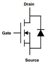
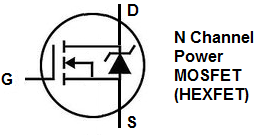
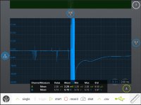
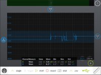
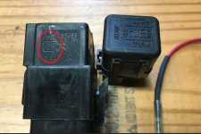
Greetings all! Playing with my labscope in the garage today and scoped a relay that didn't have a built-in flyback diode. The first capture is field collapse without a diode when the relay is turned off. Look at the scale on the right side of the screen. That spike is in excess of 100v on a 12v relay! Don't go by the measurement window at the bottom. Second capture is that same relay with a flyback diode I made wired in parallel. Much better! The diode kicks in and shunts the spike. 4th picture is how to tell if your relay has an internal diode or not. Any circuit with electronics on it really should have diode protection, either internal to the relay, or external wired in parallel. A 1N400x diode will be fine. polarity matters with a diode, they are reverse biased when used like this. Last pic is my scope, which I really like because it's fairly inexpensive for what it is.
 

Attachments

  • Spike1.JPG
    Spike1.JPG
    127.8 KB · Views: 137
  • Spike2.JPG
    Spike2.JPG
    125.6 KB · Views: 127
  • flyback-diode.jpg
    flyback-diode.jpg
    91.1 KB · Views: 120
  • Capture.JPG
    Capture.JPG
    111.5 KB · Views: 165
  • labscope.jpg
    labscope.jpg
    107.3 KB · Views: 137
Last edited:
To avoid these ads, REGISTER NOW!

MikeF2316

Well-known member
Joined
Dec 29, 2012
Messages
9,605
Location
Thornhill, ON
I always understood that symbol to be a resistor, not a diode, because of this pictogram:

0332209158-1-large.jpg


A resistor would do the same job as a diode, just less effectively. The advantage (besides a fraction of a penny of cost) is that polarity on the coil would not matter.
 

laser3kw

Well-known member
Joined
Nov 17, 2012
Messages
7,276
Location
northen IL
Diode +1, it blocks current when the field collapses after power is turned off.

Blocks?
my understanding is it shunts the spike back to common ("negative")
We install those in our equipment as precaution. We have used devices with built in dampening diodes but find that end users swap out the device with a ordinary device and then start related problems.
 

matt_i

Well-known member
Joined
Mar 14, 2008
Messages
10,726
Location
SE Michigan
This is extremely important when using any kind of electronics to control a relay.

The example that's most familiar is a PLC with DC output module, the spike can easily damage the output itself because of the spike generated by the "back EMF" of the inductive relay coil. (which is also the symbol with the diagonal line in the automotive relay)

The diodes themselves are silly cheap, I think 10pcs of a 1N4007 diode sell on ebay for ~$1.50 with free shipping. I wonder how any profit can be made...
 

Bruce Amacker

Well-known member
Joined
Nov 6, 2011
Messages
574
Location
Cleveland, Ohio
Here's a Pico capture of suppressed and non-suppressed relays showing how important it is to use suppressed relays.
 

Attachments

  • Pico cap non supressed relay.jpg
    Pico cap non supressed relay.jpg
    91.1 KB · Views: 79
  • Pico cap dampened relay.jpg
    Pico cap dampened relay.jpg
    67.5 KB · Views: 69
OP
M

mrjaw14

Well-known member
Joined
May 22, 2012
Messages
1,958
Location
Nashville, TN
Right. In my post, it's obviously a diode. In the original post, the pictogram shows a rectangle, which I took to be for a resistor.

It’s just an older relay and the symbol on the drawing is crude. Point is there’s a component in parallel to the primary coil to deal with the induced voltage. :thumbup:

There’s all kinds of components that would work for this job. As another poster pointed out though, 1N4007 diodes are cheap and work acceptably for automotive use. No reason to not use something there. If it’s not automotive the specs may be different.
 
Last edited:

mcbane

Well-known member
Joined
Jul 23, 2017
Messages
794
Location
California
Just be aware that every scope and every diode is speed limited. Just because a cheap diode makes the spike disappear from a cheap scope doesn’t mean the spike has disappeared. If you have sensitive electronics that you need to protect, consider adding a low value, like .01 uF low ESR capacitor to soak up the spike that many scopes can’t see


Sent from my iPhone using Tapatalk
 

paulsomlo

Well-known member
Joined
Jul 16, 2013
Messages
3,875
Location
Northern Colorado
I'll assume you're measuring this at the relay; how do you know that the voltage spike exists back at the ECU? In between the relay and ECU, there's probably a sizable length of wire, which has inherent inductance. I would be surprised if there weren't a protection diode back at the driver in the ECU.

Regardless, a diode is the correct circuit element for a relay snubber - a resistor of value small enough to limit the spike, would dissipate a large amount of power while the relay was energized. Now, an RC snubber (resistor in series with a capacitor) might be a suitable alternative.

And the snubbing element doesn't actually block the current; it allows it to continue through an alternate path when the relay coil's field collapses. The job of that alternate path, whether a diode, RC, whatever, is to limit the voltage spike until the energy that was contained in the field of the relay coil dissipates.
 

MBfreak

MEMBER EMERITUS
Joined
Dec 10, 2010
Messages
2,301
Location
Linkoping , Sweden
The "back emf" is of reverse polarity to the drive voltage. For the nerd, it is Lentz law in action, e=-dFi/dt.
And the diode is the right design, they are used in all applications. Billions and billions of relays use them

The only drawback, which is only a problem when you need a fast dropout, is that the current thru the relay coil and the diode will keep the armature of the relay lathed for some extra millisseconds. This can easily be managed by a zener diode in series with the snubber diode, Zener rated at typical 36 V for a 12 V relay. Will reduce the drop out time to low value and clamp the back emf at about the zener voltage.

Ola
 

dutchgray

Well-known member
Joined
Sep 28, 2014
Messages
6,467
Location
Dorset. England.
The other drawback is it makes the relay coil polarity sensitive, which I bet many dont even look at when they are replacing an ordinary relay with one with a diode.
 

frank001

Well-known member
Joined
Mar 1, 2015
Messages
665
Location
Southern California
The other drawback is it makes the relay coil polarity sensitive, which I bet many dont even look at when they are replacing an ordinary relay with one with a diode.

I have always used an MOV instead of a diode whenever I thought the 'inductive kick' from the relay coil might be a problem. MOVs have no polarity.
 
To avoid these ads, REGISTER NOW!

MikeF2316

Well-known member
Joined
Dec 29, 2012
Messages
9,605
Location
Thornhill, ON
I have a relay sitting in my box 'o' stuff. It's Bosch # 0 332 019 103. Its pictogram shows a rectangle connected across the relay's coil. That is obviously NOT a diode, because the relay clicks and the current at 14 volts is 170 mA in either direction. I popped it apart and I can see the end of blue component the shape of a typical resistor (or diode!) under the coil in a pocket. But since the relay is good, I'm not dismantling it further, which would destroy it.
 

redmondjp

Well-known member
Joined
Nov 25, 2014
Messages
2,318
Location
Redmond, WA
Diode +1, it blocks current when the field collapses after power is turned off.

No, it does exactly the opposite! When the circuit's power source is turned off, the polarity of the solenoid reverses, as it becomes a power source instead of a sink, as the collapsing magnetic field attempts to continue the current flowing. The diode allows this current to continue to flow, with the resistance of the solenoid coil dissipating the energy.

If you don't have either the diode or resistor there, you can get a tremendous voltage spike when you interrupt the current to the solenoid. At one place I worked, we were measuring 150V spikes from 12V hydraulic solenoid valves.
 

dogdog

Well-known member
Joined
Nov 15, 2011
Messages
12,711
The other drawback is it makes the relay coil polarity sensitive, which I bet many dont even look at when they are replacing an ordinary relay with one with a diode.

They'll know really fast when it blows the fuses on power up :) ask me how I Find out:)
 

dogdog

Well-known member
Joined
Nov 15, 2011
Messages
12,711
No, it does exactly the opposite! When the circuit's power source is turned off, the polarity of the solenoid reverses, as it becomes a power source instead of a sink, as the collapsing magnetic field attempts to continue the current flowing. The diode allows this current to continue to flow, with the resistance of the solenoid coil dissipating the energy.
..................

^^^^^^^^
 

laser3kw

Well-known member
Joined
Nov 17, 2012
Messages
7,276
Location
northen IL
I have always used an MOV instead of a diode whenever I thought the 'inductive kick' from the relay coil might be a problem. MOVs have no polarity.

MOV's have a shorter life span when hit with continual "spikes". That's why your are encouraged to replace power stripes yearly (or so).
I would stick with the ball peen hammer of semi conductors - the 1N4000 diode.
 

6PTsocket

Well-known member
Joined
Mar 12, 2014
Messages
4,593
I always understood that symbol to be a resistor, not a diode, because of this pictogram:

0332209158-1-large.jpg


A resistor would do the same job as a diode, just less effectively. The advantage (besides a fraction of a penny of cost) is that polarity on the coil would not matter.
The symbol is a diode; a resistor, at least in the US is a zig zag line. They are in no way interchangable. When the 12 volts is applied to the relay, the relay does not conduct and is basically invisible to the circuit. When power is removed from the relay coil, the magneic field collapses and induces a very high voltage spike into the coil that can damage the relay drive circuitry. The polarity of the spike is opposite to the voltage that operated the relay.The diode is wired to conduct in this direction and basically short circuits the coil, suppressing the spike.

Sent from my SM-G900V using Tapatalk
 

MikeF2316

Well-known member
Joined
Dec 29, 2012
Messages
9,605
Location
Thornhill, ON
The symbol is a diode; a resistor, at least in the US is a zig zag line. They are in no way interchangable. When the 12 volts is applied to the relay, the relay does not conduct and is basically invisible to the circuit. When power is removed from the relay coil, the magneic field collapses and induces a very high voltage spike into the coil that can damage the relay drive circuitry. The polarity of the spike is opposite to the voltage that operated the relay.The diode is wired to conduct in this direction and basically short circuits the coil, suppressing the spike.

Sent from my SM-G900V using Tapatalk

See post 5.
 

frank001

Well-known member
Joined
Mar 1, 2015
Messages
665
Location
Southern California
MOV's have a shorter life span when hit with continual "spikes". That's why your are encouraged to replace power stripes yearly (or so).
I would stick with the ball peen hammer of semi conductors - the 1N4000 diode.

I have used the MOVs on relays that are actuated dozens of times per day/365 days per year. The MOVs showed no signs of failure after years in service. An MOV of the proper voltage rating won't be any more prone to failure than a diode.
 

MikeF2316

Well-known member
Joined
Dec 29, 2012
Messages
9,605
Location
Thornhill, ON
Well, I found another couple of relays, so now I have one with nothing across the solenoid, one with the rectangle (that I take to be the resistor) and one with a diode. Using my Hantek 6022, I tried to get a waveform for all 3 as the relay turns off. I was unable to get a waveform for the one with nothing across the solenoid, even with 2 20:1 attenuators in series, the spike was so high it locked up the scope - I had to power it down to reset it. I include the following screenshots with identical scales, and using a 20:1 attenuator. The one with the diode shows no overshoot. The one with the resistor shows a sizable (negative) overshoot (-5.39*20+13.5) of -94.3 Volts! I believe the spike is higher, the waveform seems to show the limitations of a $80 scope! Note the 0 voltage point is the line where the yellow #1 is on the left side of the screen.

attachment.php


attachment.php
 

Attachments

  • resistor2.jpg
    resistor2.jpg
    114.8 KB · Views: 139
  • diode.jpg
    diode.jpg
    103.4 KB · Views: 134

redmondjp

Well-known member
Joined
Nov 25, 2014
Messages
2,318
Location
Redmond, WA
On cars, the biggest inductive load that gets switched is the AC compressor clutch coil. When the spike suppression device (which used to be a diode, but I am not sure what is used on modern vehicles) fails, it can cause the switching device in the compressor clutch circuit to fail prematurely due to the high voltage generated by opening the circuit - this high voltage appears across the open switching device, causing a breakdown in the transistor junction or arcing across a mechanical switch contact set.
 

theoldwizard1

Well-known member
Joined
Feb 22, 2011
Messages
43,145
Location
SE MI
On cars, the biggest inductive load that gets switched is the AC compressor clutch coil. When the spike suppression device (which used to be a diode, but I am not sure what is used on modern vehicles) fails, it can cause the switching device in the compressor clutch circuit to fail prematurely due to the high voltage generated by opening the circuit - this high voltage appears across the open switching device, causing a breakdown in the transistor junction or arcing across a mechanical switch contact set.

No EE in his right mind would use a transistor to directly switch an A/C clutch. That why they make relays. Let the 10¢ relay burn up. A diode is still a good idea because it prevents the high voltage "spike" from getting into the system and possibly causing problems elsewhere.

As previously stated, the big issue is inductive loads (anything with a coil of wire) that needs to be shut off "quickly" (fuel injectors or ignition coils). A plain diode allow the "back EMF" to keep recirculating through the device, delaying the shutoff time. There is a lot of debate on what is the "correct" Zener voltage in automotive application. I have seen it as high as 54V.
 

firworks

Well-known member
Joined
Jun 29, 2015
Messages
4,079
Location
IL
The first post definitely shows a resistor suppressed relay. There are two common symbols for a resistor, the zig-zag mentioned earlier in this thread and an empty resistor shaped outline which is what is used on that relay.

resistor-symbol.png


A resistor limits the peak voltage by providing a lower than "infinite" impedance path for the field to collapse through. There are certain applications where they are preferable to a diode. They do conduct all the time so there is some heat dissipated in them at all times, but they also allow the control side of the relay to be wired in either polarity and they provide different switch off times than a diode suppressed relay. All relays are NOT diode suppressed.
 

theoldwizard1

Well-known member
Joined
Feb 22, 2011
Messages
43,145
Location
SE MI
Well, seeing as we are getting all "techie" here, it should be noted all power MOSFETs have a built in diode to handle the back EMF from an inductive load.

engineeringtutorial.com_n-channel_mosfet_symbol.png
N-channel-power-MOSFET-symbol.png


The first image shows a plain diode and the second show a zener diode. The zener would allow the energy within the inductive load to dissipate (turn off) quicker. If the load is "large" most EE would supply an additional external diode.
 
To avoid these ads, REGISTER NOW!
Top Bottom