jerryd67
Active member
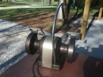
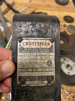
I was fortunate enough to find this "Pre-block" Craftsman Bench Grinder on local CL for $25. Unlike the later "Block" (model prefix 397 or 257), that are primarily cast aluminum, these 115 prefix models (made for Sears by Packard Electric Co.) utilized cast iron frames and wheel guards, therefore this thing is quite heavy. Was in pretty good shape for being 60 years old, and ran strong when powered on, but definitely needs freshening up.


This particular 1/4 hp model does not have covers on the wheel guards, unlike the larger 1/3 and 1/2 hp models of the same series. After removing the arbor nuts and outer flanges, I discovered the original 1959 Craftsman grinding wheels. The wheels were in good shape, but with a 60 year old grinder, it's not worth the risk to try to save them. They were challenging to get off, as they had essentially "frozen" on the arbor after 60 years.

Close-up of switch wiring.

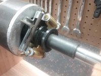
Left-hand frame housing MUST come off first on the pre-block grinders, as they have a centrifugal switch attached to the right-hand frame that acts to disengage the start-up windings when the grinder is up to speed. LH Bearing stayed on the arbor.

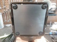
By very carefully lifting the massive winding/core assembly, I was able to get access to snip the white wire leading from the winding to the centrifugal switch (which will be replaced) and remove the winding/core assembly.

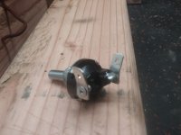
After removing the winding/core assembly, you must carefully remove the screws holding the centrifugal switch to the right-side housing, because if you attempt to remove the rotor without doing so and the right-side bearing stays on the shaft, you will damage the centrifugal switch. RH Bearing stayed in the housing for me. Close-up of the position of the centrifugal switch, which is held in by two 1/4 inch screws.

More to come!
This particular 1/4 hp model does not have covers on the wheel guards, unlike the larger 1/3 and 1/2 hp models of the same series. After removing the arbor nuts and outer flanges, I discovered the original 1959 Craftsman grinding wheels. The wheels were in good shape, but with a 60 year old grinder, it's not worth the risk to try to save them. They were challenging to get off, as they had essentially "frozen" on the arbor after 60 years.
Close-up of switch wiring.
Left-hand frame housing MUST come off first on the pre-block grinders, as they have a centrifugal switch attached to the right-hand frame that acts to disengage the start-up windings when the grinder is up to speed. LH Bearing stayed on the arbor.
By very carefully lifting the massive winding/core assembly, I was able to get access to snip the white wire leading from the winding to the centrifugal switch (which will be replaced) and remove the winding/core assembly.
After removing the winding/core assembly, you must carefully remove the screws holding the centrifugal switch to the right-side housing, because if you attempt to remove the rotor without doing so and the right-side bearing stays on the shaft, you will damage the centrifugal switch. RH Bearing stayed in the housing for me. Close-up of the position of the centrifugal switch, which is held in by two 1/4 inch screws.
More to come!
Attachments


Last edited:

.jpg")