To avoid these ads, REGISTER NOW!

BUILDING A ROLLING WORK STATION & TIDYING UP MY "MAN CAVE" [part 2]

kerrynzl

Well-known member
Joined
Nov 8, 2013
Messages
5,054
Location
Tauranga, New Zealand
On my previous thread "TIDYING UP MY "MAN CAVE" [part 1]", I had a few left over components that I needed to put to good use [Casters, Handles, Bench Top] https://www.garagejournal.com/forum/showthread.php?t=423989

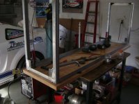
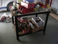
My friend Paul had loaned me a rolling work bench / parts shelf on a semi-permanent basis. [now "the day of reckoning" has approached and he needs it back]

As you can see from [photo 1] "The rubbish you collect, is in direct proportion to the space available" , and I am needing more space.

I wanted to build a rolling "work station" that looked like it was part of a matched set with my other tool cabinets which are already running out of storage space for tools [photo 2]

Again! Measure everything properly and have a good vision of what you trying to achieve [my plans were just a few numbers written down]

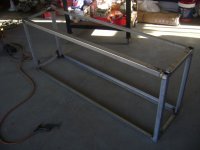
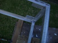
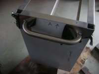
I purchase 1 length of Galvanised 40mm x 2.5mm Angle .These were a 6m length so I got 3 side pieces and 2 end pieces for the frame from 1 length. All the other pieces were offcuts from a previous trailer project. The legs were galvanised 40mm x 3mm square tubing .[photo 3]

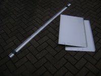
The next part required parting with $$$. I measured the end panels of my other cabinets and got a sheetmetal shop to cut and fold some stainless steel end panels for me. The inside measurement of the flange was 36mm which allowed a 40 mm square tubing to fit inside and be just shy of the round corners [no sharp edges on the stainless]

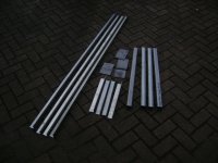
I also got 4 x pieces 1800mm long stainless steel angle folded . 2 are 40mm x 20mm profile [lowers] and 2 are 45mm x 20mm profile [uppers] [photo 4]

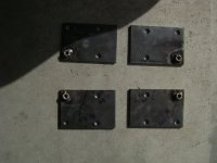
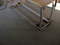
4 corner base plates were made to bolt the caster wheels to. I needed to weld 1 nut onto each corner because these will be welded directly onto the legs and there will be no access to them inside of the holes.
 

Attachments

  • 1.JPG
    1.JPG
    140.9 KB · Views: 161
  • 6.JPG
    6.JPG
    145.7 KB · Views: 112
  • 5.JPG
    5.JPG
    125.9 KB · Views: 125
  • 4.JPG
    4.JPG
    142.5 KB · Views: 126
  • 3.JPG
    3.JPG
    142 KB · Views: 134
  • 2.JPG
    2.JPG
    143.3 KB · Views: 155
To avoid these ads, REGISTER NOW!
OP
K

kerrynzl

Well-known member
Joined
Nov 8, 2013
Messages
5,054
Location
Tauranga, New Zealand
All of the galvanised 40mm Angle pieces were pre-drilled and countersunk so the bench top and bottom shelf can be attached by screws . These will both be screwed up from underneath.

Because the top and bottom pieces of angle have the flanges opposite to each other, care has to be taken to countersink the top pieces up from inside the angle, and the bottom pieces up from outside the angle. Care must also be taken not to mix them up.

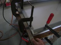
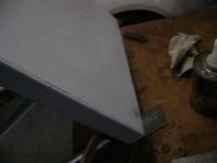
A stainless steel end panel and a pair of legs were clamped to the work bench. A ruler was used to make sure the ends weren't protruding out. [grind the legs if necessary] The stainless end panel was made square

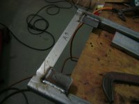
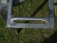
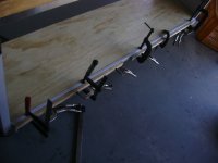
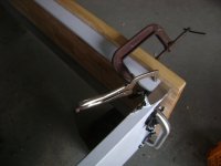
Then the correct angle pieces were clamped to the top and bottom, then it was thoroughly spot welded while clamped .Each end was marked to it's corresponding end panel. The end panel was removed and the frame was clamped again and fully welded [photos 1-3]

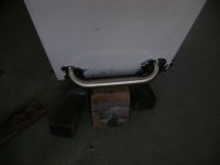
2 pieces of 50mm x 3mm Flat steel were welded flush on the top side of each end, so the handles can be bolted to it. [photo 4]
 

Attachments

  • 8.JPG
    8.JPG
    143.4 KB · Views: 71
  • 9.JPG
    9.JPG
    140.3 KB · Views: 66
  • 10.JPG
    10.JPG
    143.7 KB · Views: 69
  • 11.JPG
    11.JPG
    143.1 KB · Views: 67
OP
K

kerrynzl

Well-known member
Joined
Nov 8, 2013
Messages
5,054
Location
Tauranga, New Zealand
The welds were cleaned up with a flap disc so they were level with the surface .[so the stainless end panels will fit]

Then the handle was placed and marked for the bolt holes and also drilled. This was exactly the same position as the handles on my other cabinets.
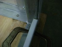
On the underside I needed to clean up the welds just around the top holes so the nuts and washers could seat properly
 

Attachments

  • 14.JPG
    14.JPG
    135.7 KB · Views: 48
  • 13.JPG
    13.JPG
    136.6 KB · Views: 59
  • 12.JPG
    12.JPG
    141.2 KB · Views: 55
OP
K

kerrynzl

Well-known member
Joined
Nov 8, 2013
Messages
5,054
Location
Tauranga, New Zealand
The bench top was placed upside down on top of Paul's work bench, and I ruled lines with a pencil for reference

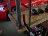
Then the 2 ends were clamped in place and the sides were checked for correct fit and clamped to the bench top. [photos 1 - 3]
once I was satisfied with this, these pieces were screwed to the bench top. And then the end frames were checked with a builders square to be 90 deg to the bench top and I clamped some diagonal braces to help keep them perpendicular [photos 4 - 5]

The diagonal braces I used were actually the lower sides angles borrowed for this purpose. Once this was all clamped and the measurements and angles were rechecked and it was spot welded together
 

Attachments

  • 15.JPG
    15.JPG
    143.7 KB · Views: 51
  • 16.JPG
    16.JPG
    142.4 KB · Views: 48
  • 17.JPG
    17.JPG
    142.6 KB · Views: 51
  • 18.JPG
    18.JPG
    144.4 KB · Views: 49
  • 19.JPG
    19.JPG
    142 KB · Views: 51
OP
K

kerrynzl

Well-known member
Joined
Nov 8, 2013
Messages
5,054
Location
Tauranga, New Zealand
After the end frames and top rails were spot welded together the diagonal braces were removed. Then they were clamped in place as the bottom side rails, and spot welded together. [photo 1]

Every measurement and angle was re-checked and the bottom side rails were fully welded while it was all still screwed to the bench top

The frame was unscrewed from the bench top and the top rails were fully welded [ I actually cheated and flipped it over and clamper it to do this ] Then all the outer welds were cleaned up with a grinder / flap disc [photo 2]

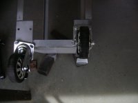
2 of the corner base plates were clamped at one end and spot welded in place [photos 3 - 4]. You can see why I previously had to weld a "blind" nut for one of the holes on each corner [refer the 1st post in this thread] The other 2 holes that are blocked by the side rails are drilled through later.

I only welded the base plates on one end at this stage, then I screwed the bench top back on and flipped it upright.
 

Attachments

  • 23.jpg
    23.jpg
    26 KB · Views: 43
  • 22.JPG
    22.JPG
    142.6 KB · Views: 44
  • 21.JPG
    21.JPG
    141.5 KB · Views: 44
  • 20.JPG
    20.JPG
    143.6 KB · Views: 46
OP
K

kerrynzl

Well-known member
Joined
Nov 8, 2013
Messages
5,054
Location
Tauranga, New Zealand
Once the bench top was screwed on properly and flipped over two pieces of plywood were slipped under each end. A spirit level was placed on the plywood pieces to confirm they were both level . [photo 1]

The bench was lifted up at the end without base plates, and remaining two base plates were slipped underneath and carefully tapped into position. A weight was put at the other end on the bench top to make sure those base plates were on firmly the plywood [and the bench wasn't "rocking"]

The other two base plates were then spot welded in place. Doing it with this procedure reduces the possibility of having uneven base plates if there is a slight twist in the frame. Generally the table will sit on 3 base plates if there is a twist in the frame [ and with the forth base plate ,the welds will bridge the clearance if it is loose ] [photo 2]

The base plates were then stitch welded then the welds were painted on the insides and underneath only with aerosol zinc paint ..I also drilled out the holes in the base plates to go through the lower rails. [also refer to previous post #5 - photo 3]
 

Attachments

  • 28.JPG
    28.JPG
    142.8 KB · Views: 32
  • 27.JPG
    27.JPG
    143.3 KB · Views: 33
  • 26.JPG
    26.JPG
    139.1 KB · Views: 34
  • 25.JPG
    25.JPG
    145.9 KB · Views: 36
  • 24.JPG
    24.JPG
    143.5 KB · Views: 36
OP
K

kerrynzl

Well-known member
Joined
Nov 8, 2013
Messages
5,054
Location
Tauranga, New Zealand
The outside welds were left unpainted so glue can adhere to the steel.

With the frame upside down 2 pieces of steel were clamped on the top edge as "stops" to locate the end panels, and it won't slip above the top edge when glued on. [photo 1 - 2]

The frame and the end panel were glued and then clamped into place with pieces of wood and lots of clamps. [photo 3] .once the glue has cured in 24 hours, the other end was glued in the same manner.

I ran a knife down the edges of the panels to remove any excess glue.
 

Attachments

  • 29.JPG
    29.JPG
    144 KB · Views: 29
  • 30.JPG
    30.JPG
    141.3 KB · Views: 29
  • 31.JPG
    31.JPG
    143.1 KB · Views: 30
  • 32.JPG
    32.JPG
    142.7 KB · Views: 29
To avoid these ads, REGISTER NOW!
OP
K

kerrynzl

Well-known member
Joined
Nov 8, 2013
Messages
5,054
Location
Tauranga, New Zealand
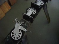
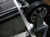
Now the casters get bolted to the frame. The fixed casters also needed to be aligned straight . How many here can claim they gave their tool bench a "wheel alignment" ? [photo 3]

I drilled through the stainless steel end panels for the handles to be bolted on. [photo 4]

The end handles were then bolted on at this stage [photos 5 - 6]
 

Attachments

  • 37.JPG
    37.JPG
    137.3 KB · Views: 35
  • 36.JPG
    36.JPG
    138 KB · Views: 32
  • 35.JPG
    35.JPG
    139 KB · Views: 35
  • 34.JPG
    34.JPG
    144.2 KB · Views: 34
  • 33.JPG
    33.JPG
    141.2 KB · Views: 35
  • 38.JPG
    38.JPG
    142.2 KB · Views: 41
OP
K

kerrynzl

Well-known member
Joined
Nov 8, 2013
Messages
5,054
Location
Tauranga, New Zealand
The bench top is screwed back on for the final time. Then I trimmed the upper stainless steel trim pieces to the correct length and shaped the ends fit inside the legs [photo 1] Note: These upper trim pieces were the 45mm x 20mm angle profile.

These trim pieces were glued and clamped to the upper side rails [photos 2 - 3]

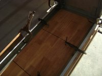
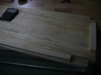
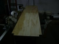
My friendly plywood supplier sold me 1/2 a sheet of 19mm thick treated plywood [3/4"] for the lower shelf

He cut the plywood to size for me, and also cut me 2 strips at 35mm wide for packers from the offcuts. The combination of 2 x 19mm thick pieces of plywood plus the 2.5mm thickness of the side angles = 40.5mm . this should be 0.5mm above the 40mm angle side rails.

The plywood strips were glued around approx. 5mm inboard from the outer edges of the underside of the lower shelf [photo 4] I needed to allow room for the bolts holding the casters so there were gaps in these strips at the ends.

Once the glue for plywood strips had cured the lower shelf was flipped over and it was given a couple of coats of clear polyurethane
 

Attachments

  • 39.JPG
    39.JPG
    140.3 KB · Views: 23
  • 40.JPG
    40.JPG
    136.1 KB · Views: 22
  • 41.JPG
    41.JPG
    144 KB · Views: 23
  • 42.JPG
    42.JPG
    138.3 KB · Views: 21
  • 43.JPG
    43.JPG
    137.5 KB · Views: 22
OP
K

kerrynzl

Well-known member
Joined
Nov 8, 2013
Messages
5,054
Location
Tauranga, New Zealand
The lower shelf was placed into the lower rails , then attached by screws from the underside using 35mm long screws [1-3/8"] which were long enough to go through the 19mm spacer strips but not show through the top. [photo 1]

You can see one of the side rails has a slight bend, [from when I had stored boxes of parts on top of it]. This will be covered by the lower stainless steel trim pieces and not seen.

The lower stainless steel trim pieces cut to length and also shaped to fit inside the legs , The lower trim pieces were the 40mm x 20mm angle profile.

These trim pieces were glued and clamped to the lower side rails and lower shelf [photos 2 - 3]

You can never have enough clamps! These pieces needed to be clamped both vertically and horizontally

Once the glue cured, I ran a knife along the edge of the stainless steel trim pieces and removed the excess glue
 

Attachments

  • 46.JPG
    46.JPG
    136.6 KB · Views: 20
  • 45.JPG
    45.JPG
    139.8 KB · Views: 19
  • 44.JPG
    44.JPG
    143 KB · Views: 24
OP
K

kerrynzl

Well-known member
Joined
Nov 8, 2013
Messages
5,054
Location
Tauranga, New Zealand
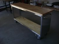
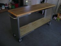
Now after waiting for the glue to cure It is finally finished .
The glue I prefer is a Bostik product called "Simson ISR 70-03" and the glue used on the plywood was "Ados F2" contact glue.

[photos 1 - 3] is the finished work bench,

I tried my best to make it appear to be part of a matched set with my toolbox set [photo 4]

There was no stainless steel welding needed in this build , just careful "daydreaming" was involved. I've had a few visitors admire my tool cabinet set...... But they don't believe this one is "homemade"
 

Attachments

  • 47.JPG
    47.JPG
    143.3 KB · Views: 63
  • 48.JPG
    48.JPG
    141 KB · Views: 59
  • 49.JPG
    49.JPG
    139.7 KB · Views: 62
  • 2.JPG
    2.JPG
    143.3 KB · Views: 71

jhn9840

Well-known member
Joined
Mar 11, 2007
Messages
1,189
Location
Northern Panhandle of WV
BUILDING A ROLLING WORK STATION & TIDYING UP MY "MAN CAVE" [part 2]

Very nice setup kerrynzl. Never would have thought of stacking two boxes like that. I’m guessing it saves you a lot of floor space.

jhn9840
John


Sent from my iPhone using Garage Journal
 
OP
K

kerrynzl

Well-known member
Joined
Nov 8, 2013
Messages
5,054
Location
Tauranga, New Zealand
Re: BUILDING A ROLLING WORK STATION & TIDYING UP MY "MAN CAVE" [part 2]

Very nice setup kerrynzl. Never would have thought of stacking two boxes like that. I’m guessing it saves you a lot of floor space.

jhn9840
John


Sent from my iPhone using Garage Journal

Hahaha! I got the idea of stacking toolboxes from your avatar :beer:
Seriously I just searched Google images for ideas.

Having the wooden bench on top was a blessing in disguise, I store drop-saws and all my cordless drills and chargers up there

The tool cabinets are available in 55", 72", and 96" so you just measure to what is suitable for your garage. [I used 3 x 72"]

The reason I chose stainless is in NZ we are the land of UV [you can get sunburnt in 8-12 minutes]
The power coating on those toolboxes will look faded after 6 months

cheers Kerry
 
To avoid these ads, REGISTER NOW!
Top Bottom