To avoid these ads, REGISTER NOW!

A Hardinge TL lathe project

Oregon rock crusher

Well-known member
Joined
Jun 28, 2016
Messages
1,906
Location
West of Salem
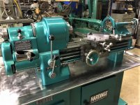
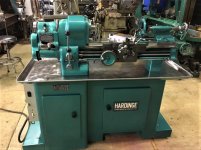
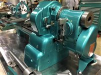
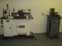
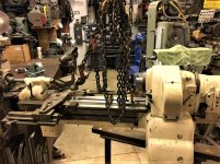
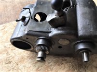
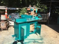
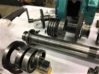
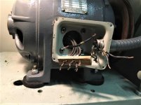
So about 15 years ago or there about I bought this Hardinge TL lathe that popped up on the local CL. The TL lathes had been introduced by Hardinge in the late 30's and this one, S/N 18651, was made in 1942. During the war tool room lathes tended to get used hard. It had a few issues but the biggest problem was the motor and controls were missing. The previous owner had bolted in a single phase motor and scabbed on a drum switch to operate it but it was a pretty poor substitute for the original set up. The other big problem was the spindle had excessive play in it, about .005, and from everything I had read replacing the bearings would be both an expensive and challenging chore.

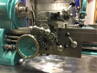
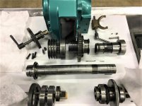
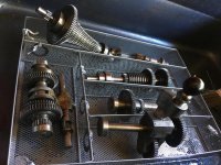
On the plus side the lathe had many accessories including steady and follow rests. (TL follow rests are quite rare). A Royal lever collet closer was fitted and three and six jaw chucks included. The lathe has a quick change gear box but also included all the original extra change gears. Also a taper attachment and quite a few collets, and a bunch of other tooling. Also the bed is not that worn for a TL.

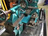
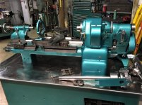
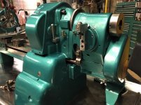
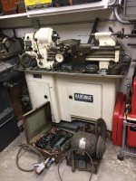
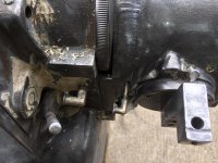
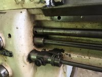
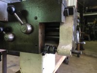
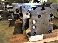
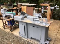
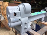
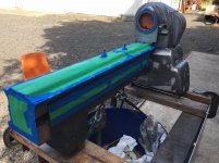
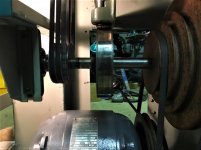
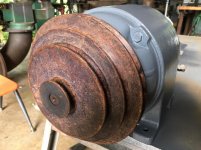
I've kept my eyes open all these years but the first good break came this summer in early July when I saw a fairly local guy was parting out a DV59 which used a very similar drive. I drove up on a Sunday morning and made a deal for the complete drive including the two speed motor, counter shaft with step shieves, and the control panel. All untested so I'm taking a bit of a chance on this drive. No more excuses....time to get to work. A few pics of the lathe before the tear down....this won't drag out too long....I'm almost done now. Ed.
 

Attachments

  • IMG_0481.jpg
    IMG_0481.jpg
    135 KB · Views: 128
  • IMG_1688.jpg
    IMG_1688.jpg
    119.3 KB · Views: 100
  • IMG_1687.jpg
    IMG_1687.jpg
    141.4 KB · Views: 110
  • IMG_1686.JPG
    IMG_1686.JPG
    124.9 KB · Views: 116
  • IMG_1690.jpg
    IMG_1690.jpg
    105.9 KB · Views: 123
  • IMG_1684.jpg
    IMG_1684.jpg
    114.2 KB · Views: 120
  • IMG_1683.jpg
    IMG_1683.jpg
    118.5 KB · Views: 140
To avoid these ads, REGISTER NOW!

bmwrd0

Well-known member
Joined
Nov 7, 2010
Messages
5,455
Location
Beaver Fever Oregon
That is really nice Ed, good luck with it! Knowing you, luck probably isn't needed. By the way, it was good to see you the other weekend.
 
OP
O

Oregon rock crusher

Well-known member
Joined
Jun 28, 2016
Messages
1,906
Location
West of Salem
Thanks Beemer. It was good seeing you at the swap as well. Hope you found some nice stuff. I pulled a few things out but nothing too exciting. Not sure about not needing the luck though. This lathe has really put me to the test. Ed.
 
OP
O

Oregon rock crusher

Well-known member
Joined
Jun 28, 2016
Messages
1,906
Location
West of Salem
The basic tear down was fairly straight forward. I pulled the lathe bed off the cabinet intact and set it on it's own cart which gave easy access to break the lathe down into several sub assemblies. One recurring theme with Hardinge is they used a lot of hex head set screws throughout and they nearly always put a 2nd one on top of the first one.

The headstock comes off the lathe bed fairly easy which was a pleasant surprise. Also helpful for working on it is that it can lock onto the bed anywhere forward or backwards. The carriage can't come off until the back bed plate is removed and the feed rod and stop rods unhooked from the gear box.

The Gear box itself is probably the most difficult thing to remove and there is one bolt hidden inside that would be a real dog to find if you didn't know where to look. I tried to only break down and work on one sub assembly at a time to keep from getting too much lathe scattered around. A few pics of the tear down. Ed.
 

Attachments

  • IMG_1726.jpg
    IMG_1726.jpg
    94.2 KB · Views: 85
  • IMG_1725.jpg
    IMG_1725.jpg
    112.7 KB · Views: 80
  • IMG_1724.JPG
    IMG_1724.JPG
    144.6 KB · Views: 78
  • IMG_1704.JPG
    IMG_1704.JPG
    112.4 KB · Views: 77
  • IMG_1703.JPG
    IMG_1703.JPG
    106.8 KB · Views: 72
  • IMG_1702.jpg
    IMG_1702.jpg
    119 KB · Views: 77
  • IMG_1699.jpg
    IMG_1699.jpg
    150.2 KB · Views: 82
OP
O

Oregon rock crusher

Well-known member
Joined
Jun 28, 2016
Messages
1,906
Location
West of Salem
Getting the rest of the parts off and cleaned up wasn't too bad. The spindle with both front bearings came out without too much resistance. These are matched axial load bearings which have marks on the races where runout was minimal that need to be aligned with each other and the spindle. Hardinge reportedly did the final grinding on the spindle with them installed.

There are several ways to install the bearings and I think a PO had pulled the spindle at one time to replace drive belts and had not got them back in proper orientation and had not tensioned them correctly. Hopefully this will turn out to be the only problem with the spindle. I got down to a bare bed and had most of the paint removed at this point.

The lead screw retaining nut is buried behind the gearbox and was about the last thing to get stripped from the bed. It was very tight and my first attempt at making a pin wrench failed so I had to go with a much heavier tool. Hardinge used needle bearings for the control shafts and most of them were packed with dried grease and ****. A soaking in hot simple green cleaned them up though. A few more pics getting to a bare bed. Ed.
 

Attachments

  • IMG_1768.jpg
    IMG_1768.jpg
    145 KB · Views: 69
  • IMG_1761.jpg
    IMG_1761.jpg
    90.7 KB · Views: 62
  • IMG_1759.JPG
    IMG_1759.JPG
    126.7 KB · Views: 65
  • IMG_1756.jpg
    IMG_1756.jpg
    105.5 KB · Views: 75
  • IMG_1742.jpg
    IMG_1742.jpg
    98.6 KB · Views: 73
  • IMG_1741.JPG
    IMG_1741.JPG
    112.5 KB · Views: 71
  • IMG_1738.JPG
    IMG_1738.JPG
    137.1 KB · Views: 72
OP
O

Oregon rock crusher

Well-known member
Joined
Jun 28, 2016
Messages
1,906
Location
West of Salem
The gearbox was really filthy and badly needed cleaned up. Hardinge used shims between the cases and the bearings and keeping track of where they all came from took a system. I put all the shafts in multi compartment wire basket and wired the shims to the basket in the order they came out. I used diesel in the parts washer for clean up and it worked well and helped soften the old bearing grease. I did end up replacing most of the bearings on the ends of the shafts but kept a few needle bearings as they cleaned up really well. The gears were in great shape for their age. QC gearbox pics. Ed.
 

Attachments

  • IMG_1971.jpg
    IMG_1971.jpg
    154.4 KB · Views: 73
  • IMG_1852 Large.jpg
    IMG_1852 Large.jpg
    150 KB · Views: 69
  • IMG_1848.jpg
    IMG_1848.jpg
    133.7 KB · Views: 64
  • IMG_1844.jpg
    IMG_1844.jpg
    130 KB · Views: 63
  • IMG_1843.jpg
    IMG_1843.jpg
    145.5 KB · Views: 61
  • IMG_1804.jpg
    IMG_1804.jpg
    71.8 KB · Views: 60
  • IMG_1840.jpg
    IMG_1840.jpg
    120.2 KB · Views: 61
Last edited:
OP
O

Oregon rock crusher

Well-known member
Joined
Jun 28, 2016
Messages
1,906
Location
West of Salem
With the major components stripped it was time for some paint prep. The carriage only had one handwheel that got paint so I left it's clean up for later. The tailstock, taper attachment, steady and follow rests also broke into components fairly easy. I did do one modification to the cabinet by putting casters on it and adding jack screws at the corners. I made sheet metal covers to go over the casters. The casters will make it much easier to get the lathe back in the tool room where it will stay until the kids are tasked with moving it out. Lots of sanding and some filling to get everything smoothed up and paint ready. I used liquid steel and plastic for filler depending on location.
 

Attachments

  • IMG_1870.jpg
    IMG_1870.jpg
    144.9 KB · Views: 65
  • IMG_1868.JPG
    IMG_1868.JPG
    124.5 KB · Views: 65
  • IMG_1867.jpg
    IMG_1867.jpg
    146 KB · Views: 61
  • IMG_1865.jpg
    IMG_1865.jpg
    145 KB · Views: 62
  • IMG_1864.jpg
    IMG_1864.jpg
    144.2 KB · Views: 64
  • IMG_1861.jpg
    IMG_1861.jpg
    135.2 KB · Views: 62
  • IMG_1857.jpg
    IMG_1857.jpg
    143.5 KB · Views: 65
OP
O

Oregon rock crusher

Well-known member
Joined
Jun 28, 2016
Messages
1,906
Location
West of Salem
Paint day came and went fairly well. I had used a aqua green color a few years ago on a monoset grinder I'd restored and tried to match it. I had help from a nice gal who runs the industrial paint supply store and I'm not sure I got a perfect match but was fairly happy with the color. Paint prices have gone up since last time I bought some. I do have enough left for a few more machines though.
 

Attachments

  • IMG_1936.JPG
    IMG_1936.JPG
    137.3 KB · Views: 60
  • IMG_1935.jpg
    IMG_1935.jpg
    145.2 KB · Views: 64
  • IMG_1934.JPG
    IMG_1934.JPG
    144.3 KB · Views: 63
  • IMG_1933.jpg
    IMG_1933.jpg
    134.8 KB · Views: 62
  • IMG_1932.jpg
    IMG_1932.jpg
    142.4 KB · Views: 61
  • IMG_1931.jpg
    IMG_1931.jpg
    131.1 KB · Views: 65
  • IMG_1930.jpg
    IMG_1930.jpg
    141.9 KB · Views: 68
OP
O

Oregon rock crusher

Well-known member
Joined
Jun 28, 2016
Messages
1,906
Location
West of Salem
The headstock went back together fairly well. Keeping the bearing races oriented correctly (they have "v" marks on both races to align) and pulling the spindle into the bore went well. I used a threaded rod with a few different length spacers to smoothly pull it all together. The B&D workmate was the perfect vise for this as it held the headstock firmly and allowed excellent access through the bottom for the drive shieve and clutch assembly.

The rear tension nut pulls everything tightly to the spindle and sets the bearing pre-load. I didn't have the proper pin wrench for the nut so I put cut of 5/16" bolt heads in the nuts holes and used the big channel locks.That worked well and I didn't mar the nut at all. There are a few pitfalls to avoid but really it's not that difficult a task. Just make sure the shifting fork is in place with the clutch and don't forget to put the belts on. I did keep everything as clean as possible and pre-oiled the bearings with spindle oil. A few pics of the headstock components and assembly. Ed.
 

Attachments

  • IMG_2109.jpg
    IMG_2109.jpg
    109.8 KB · Views: 68
  • IMG_2102.JPG
    IMG_2102.JPG
    87.8 KB · Views: 67
  • IMG_2099.JPG
    IMG_2099.JPG
    101.5 KB · Views: 68
  • IMG_2089.jpg
    IMG_2089.jpg
    130.8 KB · Views: 72
  • IMG_2087.jpg
    IMG_2087.jpg
    53.4 KB · Views: 69
  • IMG_2074.jpg
    IMG_2074.jpg
    104 KB · Views: 73
  • IMG_2073.jpg
    IMG_2073.jpg
    102.1 KB · Views: 77
OP
O

Oregon rock crusher

Well-known member
Joined
Jun 28, 2016
Messages
1,906
Location
West of Salem
The gearbox was another assembly that took some time. I had taken each shaft apart one at a time for cleaning and bearings and returned them to the wire rack with their shims just as they had come out. Each shaft went back in exactly in the reverse order they had come out. The shims were a little tough to keep in the upper case as I closed it up but with a dab of grease on them I thing they are where they belong. I was so focused on keeping everything straight I didn't get many pics of the shafts going in.
 

Attachments

  • IMG_2011.JPG
    IMG_2011.JPG
    97.4 KB · Views: 61
  • IMG_2020.jpg
    IMG_2020.jpg
    86.1 KB · Views: 57
  • IMG_2019.jpg
    IMG_2019.jpg
    113.9 KB · Views: 59
  • IMG_2018.jpg
    IMG_2018.jpg
    99.4 KB · Views: 54
  • IMG_2017.jpg
    IMG_2017.jpg
    98.5 KB · Views: 56
  • IMG_2016.jpg
    IMG_2016.jpg
    85.2 KB · Views: 54
  • IMG_1972.jpg
    IMG_1972.jpg
    149.7 KB · Views: 59
OP
O

Oregon rock crusher

Well-known member
Joined
Jun 28, 2016
Messages
1,906
Location
West of Salem
About the last things to do involved the drive and it's connections to the lathe's controls. The DV59 donor drive I picked up used the same size and steps on the shieves as my TL's except they were phenolic construction instead of aluminum. They look good so I used them. The motor fit my TL hinge plate perfectly. I used my TL countershaft because it was a little longer than the donor shaft as it had a brake rotor. I had already fitted the starter and drum switch housing on the lathe cabinet making sure to get the drum switches in line with the TL's controls.

The brake system is a bit of a bear to get adjusted right. I ended up bending my actuator arm to get it to work right. The brake itself if just a magnum wine bottle cork but it seems to work well. Kind of a ***** getting all of the in cabinet connections and adjustments right but it came together. The drive was a little buzzy at first so I had to take the starter apart and clean the contacts on it and some of the drum switches but have it working smooth and quiet now. A few details to work out but it's getting really close now. Ed.
 

Attachments

  • IMG_2145.jpg
    IMG_2145.jpg
    120.7 KB · Views: 62
  • IMG_2231.jpg
    IMG_2231.jpg
    98.7 KB · Views: 56
  • IMG_2230.jpg
    IMG_2230.jpg
    109.2 KB · Views: 58
  • IMG_2139.jpg
    IMG_2139.jpg
    87.9 KB · Views: 58
  • IMG_2144.JPG
    IMG_2144.JPG
    143.5 KB · Views: 57
  • IMG_2129.jpg
    IMG_2129.jpg
    131.8 KB · Views: 56
  • IMG_1754.jpg
    IMG_1754.jpg
    131.4 KB · Views: 59
OP
O

Oregon rock crusher

Well-known member
Joined
Jun 28, 2016
Messages
1,906
Location
West of Salem
Down to short strokes now. I had to rework the Hardinge name and info plates but really just cleaning them up and a quick coat of clear. I still have some of the tooling to clean up as well and I just got the collet rack back in the cabinet. Just a few more pics for now....and thanks for following along if you've made it this far. :) Ed.
 

Attachments

  • IMG_2199.jpg
    IMG_2199.jpg
    140.3 KB · Views: 76
  • IMG_2198.jpg
    IMG_2198.jpg
    117.9 KB · Views: 72
  • IMG_2197.jpg
    IMG_2197.jpg
    130.5 KB · Views: 73
  • IMG_2196.jpg
    IMG_2196.jpg
    119.2 KB · Views: 70
  • IMG_2123.jpg
    IMG_2123.jpg
    113.9 KB · Views: 58
  • IMG_2220.JPG
    IMG_2220.JPG
    58 KB · Views: 56
  • IMG_2217.jpg
    IMG_2217.jpg
    87.1 KB · Views: 66

SweetD

Well-known member
Joined
Feb 8, 2010
Messages
3,265
Location
Rhode Island
Really nice work and thanks for the detailed post. I hope you get many years of use out of her!

Dave
 
To avoid these ads, REGISTER NOW!
OP
O

Oregon rock crusher

Well-known member
Joined
Jun 28, 2016
Messages
1,906
Location
West of Salem
Thank you Larry, Dave, JoCo, and Royce. It'a a bit of a relief to be nearly done with this project. The last really big thing to do is route 240v 3 phase power from my phase perfect to the lathe. The original motor was 440v and I had taken the power from the PP through a transformer to get the higher voltage and had that fed to the tool room. I didn't expect to need both voltages in there as most motors can go high or low volts....but not this one. I have a small Hardinge BB4 milling machine that also runs on 440v only to pair with the lathe, maybe it's due for some green paint too. Ed.
 

2oolhound

Well-known member
Joined
Dec 18, 2010
Messages
5,918
Location
BC Canada
it's it's ...beautiful

and the taper attachment looks ... well, hardinge. would like to see another shot of that eventually AND, is that a BLACK HOLE! or is it the hole through centre? It's massive.

Thank You for an amazing post and the great photos! :drool:
 
OP
O

Oregon rock crusher

Well-known member
Joined
Jun 28, 2016
Messages
1,906
Location
West of Salem
Thanks 2oolhound. The spindle is set up to take 5c collets directly and through hole diameter is a pretty big deal. This little Hardinge has enough space to get most sporting barrels through for chambering and is set up pretty well for a spyder on the back end.
Here's a few more pics of the back side with the taper. I still have a few things to button up and then make a few chips and see how accurate she is. Ed.
 

Attachments

  • IMG_2240.jpg
    IMG_2240.jpg
    127.5 KB · Views: 72
  • IMG_2241.jpg
    IMG_2241.jpg
    127.4 KB · Views: 68
  • IMG_2243.jpg
    IMG_2243.jpg
    123.6 KB · Views: 68
  • IMG_2244.jpg
    IMG_2244.jpg
    110.3 KB · Views: 61
  • IMG_2245.jpg
    IMG_2245.jpg
    111.3 KB · Views: 66
  • IMG_2247.jpg
    IMG_2247.jpg
    116.3 KB · Views: 80

Dave455

Well-known member
Joined
Mar 19, 2013
Messages
5,803
Location
Sussex, England
That’s a great job, and I love the colour!

Hardinge are superb machines. I firm I work with have one very similar, and I quite covet it, but it’s a favourite of the owner, so I don’t rate the chances of getting my paws on it!
 

WhoWhatNow

Well-known member
Joined
Feb 22, 2011
Messages
1,885
Location
Collegeville, PA
That is beautiful work. I would love to see a video of it running.

With the precision and the high speeds that these lathes are capable of, I wonder if it would make a good platform for a CNC conversion.
 
OP
O

Oregon rock crusher

Well-known member
Joined
Jun 28, 2016
Messages
1,906
Location
West of Salem
Thank you Dave and WhoWhatNow. I really like the color too and plan to use it on a couple other machines including my little Hardinge BB4. Just not ready to take on another paint job just now. Too much work prepping. I'm not sure how successful a full cnc conversion would be on a mechanical feed machine like this but they do convert the hlv-h machines. I am happy with the manual controls the way it is but a set of scales might be nice. Ed.
 

DocsMachine

Well-known member
Joined
Sep 16, 2006
Messages
1,857
With the precision and the high speeds that these lathes are capable of, I wonder if it would make a good platform for a CNC conversion.

-Yes, they do. But a better option would be to find something like a Hardinge Omni-Turn, which is basically the same lathe but with a (now antique) CNC control.

Strip off the old electronics, throw on something like a Mac 3 or better yet a Centroid Acorn controller, and Robert is your Aunt's Husband. :D

There's also much older Hardinges, that use a very primitive timer control. There's no computer or tape reader or anything- there's simply a "plug board" into which you place jumpers, set a few timers, and it's basically an automatic turret lathe.

These you can find for pennies per pound, though more and more people are picking them up specifically for a modern CNC control conversion so you'd want to act quick. :D

Doc.
 

shocktower

New member
Joined
Dec 25, 2021
Messages
2
Location
Canby Oregon
Hello ORC I am a fellow Oregon TL Owner, mine got a little abused during shipping but otherwise pretty good right now in pieces . I really like your refurbish of yours the one I have is USN model very short bed I don't remember the exact length will measure tomorrow , Oh yeah the hidden allen head cap screw o_O
 

Steve from Socal

Well-known member
Joined
Jan 27, 2009
Messages
3,491
Location
Hutchinson Ks.
I didn't see this while you were doing the work but, fantastic job. The color looks close to the green Powermatic used on machinery in the 60~70's. Beautiful restoration, a wonderful piece of iconic machine tool art.

Steve
 
OP
O

Oregon rock crusher

Well-known member
Joined
Jun 28, 2016
Messages
1,906
Location
West of Salem
Good find on your navy TL shocktower and welcome to the forum. TL's in general are not that common to find and with most made just before and during the War they got used up pretty fast. The carriage seems especially prone to wear. Have you found the S/N and the year it was made yet.

Thanks Steve. The TL was a good project for me and I am a fan of both shades of Powermatic green. I've painted several machines green over the years but this is the closest I've come to a favorite green so far. Ed.
 

shocktower

New member
Joined
Dec 25, 2021
Messages
2
Location
Canby Oregon
Good find on your navy TL shocktower and welcome to the forum. TL's in general are not that common to find and with most made just before and during the War they got used up pretty fast. The carriage seems especially prone to wear. Have you found the S/N and the year it was made yet.

Thanks Steve. The TL was a good project for me and I am a fan of both shades of Powermatic green. I've painted several machines green over the years but this is the closest I've come to a favorite green so far. Ed.
This one did not get much use and I believe it is a 1943 Tl-10 SP I will get the serial number tomorrow it is to cold to walk to the shop and it is snowing I do need to find a few parts to repair it from Oak Harbor
 
To avoid these ads, REGISTER NOW!
Top Bottom