
rattle_snake
Well-known member
Had several request about my shop speaker system but info is scattered in shop build thread across 4 different pic hosting sites including broken photofuckit, so here is the condensed version. My passion for loud music lead me to start building speakers when I was 13 with my dad's tools. By the end of high school I had designed and built a lot of speaker boxes using software from a floppy disk. I went on to get my electrical engineering degree and worked with audio/acoustic among other things. This project took about 2 years as I was building the building at the same time.
The main speakers are a leftover Rockford Fosgate 6.5" component set that was collecting dust in my closet. I build simple rectangle enclosures without regard to volume as they are bi amp'd/high pass filtered above the frequencies that the cone moves much. Passive filters are on the outside.


The sub enclosures are simple 2nd order (ported) with design goal of high output at very low frequency (20-40). Trade-off is reduced efficiency (not as loud). To keep port velocity low, two 4" pipes are used, but have to be really long to get low resonant frequency. So a brace is used to support the inner end.

Using a free online box calculator, the enclosures are 2.9 cu ft (net) and have a system Fs of 28 Hz. This yields a -3db point (half power) at 27 hz, and a small peak/bump at 33hz. Given room reflections the system is flat below 20hz.
The subs are Rockford Fosgate 12" P3s, and are the only thing I bough new, however I got them at cost as my wife was a former employee now contractor. They are dual 2 ohm wired in series to get 4 ohm nominal. The ports are abut 25" long, but the opening needs to be at least one diameter away from the wall. The driver, brace and port volumes also have to be added to the box volume so gross box volume is around 3.4 cu ft.

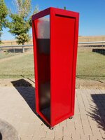
The box ratio started as golden (1.6:1.0:0.6) with adjustments to fit driver on medium side and port length. The brace is cut to help equalize pressures, and not create any additional chambers. The box walls are lined with Dacron to reduce standing waves, and also effectively (although slightly) lower required box volume to achieve the target Q/Fs by increasing damping.

Once complete I tested by doing manual frequency sweep with simple volt meter to determine tune frequency and adjusted port length to fit software target projections.
To calculate resonant frequency from impedance curve, I used a 4 ohm high power resistor to make a voltage divider/current sense. This allows the drive level differences to be negated. I then measured voltage across the coils in series and the resistor to back calculate resistance at several frequencies.
The min value is the system Fs, which was 6 ohms. above and below this the resistance is higher and the amp doesn't have to deliver as much power to achieve the same output.
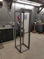
They remained unfinished for a long time;

The speaker are driven with pro audio gear I found used on CL and Ebay. I built a temporary 19" rack out of 2x4s. Signal flow is a Bluetooth to analog adapter into 1/3 octave EQ, 2 way x-over, amps. 1700 watts. The amps are old and needed some of the electrolytic capacitors replaced to operate properly. The are an odd floating rail design with a virtual gnd. The speaker current goes through the power supply capacitors. If the demanded output voltage goes above the nominal rail voltage, the rail is driven up to allow a higher voltage.

I eventually built a shelf to get the gear off the ground. I bought a cheap calibrated mic and tuned/flattened the system with a RTA app on my phone. The result was impressive for the $, especially the low end. Tone were brutal and shook the building. What I didn't realize at the time was that the sub amp's 50 Hz high pass filter was turned on, effectively filtering out bass below 50...

The main speakers are a leftover Rockford Fosgate 6.5" component set that was collecting dust in my closet. I build simple rectangle enclosures without regard to volume as they are bi amp'd/high pass filtered above the frequencies that the cone moves much. Passive filters are on the outside.
The sub enclosures are simple 2nd order (ported) with design goal of high output at very low frequency (20-40). Trade-off is reduced efficiency (not as loud). To keep port velocity low, two 4" pipes are used, but have to be really long to get low resonant frequency. So a brace is used to support the inner end.
Using a free online box calculator, the enclosures are 2.9 cu ft (net) and have a system Fs of 28 Hz. This yields a -3db point (half power) at 27 hz, and a small peak/bump at 33hz. Given room reflections the system is flat below 20hz.
The subs are Rockford Fosgate 12" P3s, and are the only thing I bough new, however I got them at cost as my wife was a former employee now contractor. They are dual 2 ohm wired in series to get 4 ohm nominal. The ports are abut 25" long, but the opening needs to be at least one diameter away from the wall. The driver, brace and port volumes also have to be added to the box volume so gross box volume is around 3.4 cu ft.
The box ratio started as golden (1.6:1.0:0.6) with adjustments to fit driver on medium side and port length. The brace is cut to help equalize pressures, and not create any additional chambers. The box walls are lined with Dacron to reduce standing waves, and also effectively (although slightly) lower required box volume to achieve the target Q/Fs by increasing damping.
Once complete I tested by doing manual frequency sweep with simple volt meter to determine tune frequency and adjusted port length to fit software target projections.
To calculate resonant frequency from impedance curve, I used a 4 ohm high power resistor to make a voltage divider/current sense. This allows the drive level differences to be negated. I then measured voltage across the coils in series and the resistor to back calculate resistance at several frequencies.
The min value is the system Fs, which was 6 ohms. above and below this the resistance is higher and the amp doesn't have to deliver as much power to achieve the same output.
They remained unfinished for a long time;
The speaker are driven with pro audio gear I found used on CL and Ebay. I built a temporary 19" rack out of 2x4s. Signal flow is a Bluetooth to analog adapter into 1/3 octave EQ, 2 way x-over, amps. 1700 watts. The amps are old and needed some of the electrolytic capacitors replaced to operate properly. The are an odd floating rail design with a virtual gnd. The speaker current goes through the power supply capacitors. If the demanded output voltage goes above the nominal rail voltage, the rail is driven up to allow a higher voltage.
I eventually built a shelf to get the gear off the ground. I bought a cheap calibrated mic and tuned/flattened the system with a RTA app on my phone. The result was impressive for the $, especially the low end. Tone were brutal and shook the building. What I didn't realize at the time was that the sub amp's 50 Hz high pass filter was turned on, effectively filtering out bass below 50...
Last edited:


")


