Fix Until Broke
Well-known member
We got a bit off track over in the "Lift Modifications - Let's See Them" thread so this thread was created to clean that one up and give a more relevant place to have this discussion.
Please feel free to continue discussions below so as to keep the lift modifications thread clean. A link to this thread will be placed over there and vice versa to cross reference.
Please feel free to continue discussions below so as to keep the lift modifications thread clean. A link to this thread will be placed over there and vice versa to cross reference.
Folks, what in general do you use to screw something on the posts (e.g. outlets)? Self tapping screws, or screws with nuts or..?
If I'm bringing 220v to the outlet, can I "steal" 1 hot wire from it to make 110v outlet next to 220v outlet (I personally think no) or I need to have a separate dedicated wires for 110v outlet?
Yes you can. Just use one leg from your 240v (either the black or the red wire) and the white to create your 120v receptacle.
110/ 220 has been replaced over the years by 120/240.
Thanks for the response. I meant I knew how I can do it (physically). But looking from the point of view of electrical codes - is this something permitted or not permitted to do in general?
As long as the circuit is sized properly, meaning your usage isn't going to exceed the amperage of the breaker, and you use the proper gauge wire, I don't see a problem. You should even be able to put both receptacles in the same duplex box. Sometimes finding the cover plate in the right configuration can take a little searching, but it can be done.
Thank you! I’m planning to go with 6 gauge wire with 50A breaker. Hopefully it will be possible to feed it through the metal conduit with a lot of turns")
Where is the neutral coming from?
From the breaker box.
You can't put a 15 or 20 amp outlet on a 50 amp breaker. It's against code.
What is it you are connecting to this? Not only is it dangerous to connect a 20A recept to this the lift is too.
I don’t have anything particular to connect to it, but I thought I may have the 6-50 outlet reserved for a welder or air compressor or something else from that nature.
I wanted to run the wire from the box to the lift, connect the lift directly and to have one 240v outlet (just in case) and also to have 120v outlet next to it, since there cannot be too many 120v outlets in the garage.
That’s why I was asking if it is possible to steal the one hot wire from 240v outlet to create a 120v next to it. Do you know if is up to the code to run 240v wiring and 120v coming from a separate breakers in the same metal conduit?
You can put both in the same pipe but not all 50A welders need number 6, very few do. Your hoist will be limited to a 30 circuit. The pipe to mine has a 240 circuit and some 120v ones.
Run 4 wires rated for 50A (or whatever current your breaker will be) over to the hoist.
- Black = 120v "A" phase
- Red = 120v "B" phase
- White = Neutral (can be smaller 12 gauge wire depending on length)
- Green = Ground
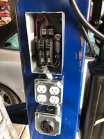
Wire in your 240 outlet for the welder using Red, Black and Green. Tap off each side of the 240 outlet with the same gauge wire and run to a pair of 15 or 20 amp breakers in a sub panel like shown below and then power a "quad box" with each duplex outlet fed by one of the 15 or 20 amp breakers. White is the neutral for the 120v outlets, Green is ground again. The white wire can carry the current for both 120v circuits simultaneously since they're out of phase.


Here's another option with both combined in one box. It's $80 and you probably don't need the IP65 rating, but it's clean.
https://www.asi-ez.com/member/~RAI-DAC-109-B.asp?
"The white wire can carry the current for both 120v circuits simultaneously since they're out of phase." Careful with this. Size the white for the combined current or run two of them. The wire size tables are done assuming only a single phase. The reason you can use that size (or smaller) for 220V is the current goes from hot-hot and should not be returning thru neutral or ground. You also need the 50A wire to the sub-panel since those wires are on a larger breaker but you can use the smaller gauge after that. Code may vary depending on your location or inspector!
As you noted, the white is not used on the 240 circuit so I don't think I led anyone astray there.
I was not aware that some/any/all of the wire tables were done assuming single phase only. We ran common neutral on 3 separate phases of 120v/20A circuits from a 480/120 transformer with a single 12AWG wire. I questioned this with the electrician and inspector and they both agreed that it was no problem due to the phasing.
Agreed that the 50A wire needs to be run to the sub panel - good catch, I've edited my post to reflect this.
Thanks guys! Good idea about the subpanel.
And you are correct about the white wire. I'm an engineer, not an electrician and was thinking that both phases were trying to return current thru the white wire. That isn't what happens. When you plug something into each socket, the white wire returns current from one leg to the other rather than combining currents and returning the to the source. The white wire is therefore never exceeding its current rating. In fact, other than between the sockets, current back to source should be zero if both sockets are evenly loaded.
The current tables for AC wire are RMS which averages to DC current. Unless the current is going back thru the other supply leg(s) you would have some point that has excess current if multiple legs are supplying into the same wire. But in normal two and three phase, it goes back up one of the other supply legs so you don't have an issue. In electronics, I have lots of circuits where that is not a given--current is usually allowed to flow in only one direction so it becomes additive.
I think we're saying the same thing, but maybe in different ways? I'm not an electrician either (also an engineer so maybe we're the blind leading the blind
On the 240v circuit the current goes back/forth between the black and red wires - no neutral or ground necessary (recommended for safety, but not necessary for operation).
On the 120v circuits the current goes back/forth between the black and white wires on one outlet and between the red and white wires on the other outlet. Since the current on the black and red wires are out of phase, when the current is high on the black wire, it's low on the red wire so the current on the white wire is ~constant.
Any electricians able to straighten us out here?
Close. Better way to say the same thing I think?--When voltage is high on red it's low on black so current flows from red to black. White will be zero or neutral unless there is an offset in the voltages. So that is why the white isn't needed at just a 220V socket. Ground is needed for safety.
The white wire has to be at least the current capacity of the red and black if you want to wire for 120V. The current will flow to white if you only plug into one outlet or the other as described above.
If I were to do this wiring on something I own I would absolutely check to make sure that the white wire is connected to neutral/ground at the main panel. I do rental houses, some of which are old, and if a wire wasn't needed, it often wasn't connected.
Again, I'm not sure exactly what the NEC says about some of this.
Agreed on the 240v circuit - no neutral needed - Size the red/black wires for the full 50A to this plug.
On either of the 20A 120v circuits, if you plug a drill into one of them (Black for example), the white and black wire will carry the same current at the same time (ignoring power factor here) - Let's call it 4 amps RMS.
If you plug a halogen light into the Red circuit that draws 10 amps RMS and use the 4 amp RMS drill at the same time there will NOT be 14 amps RMS in the white wire, instead it will be 6 amps - the difference between the two loads since they're out of phase. The white wire will only carry the difference in current between the red and black wire at any point in time, not the sum of the current in the red and black wires.
Much better explained in the link below by those who know what they're doing
https://www.allaboutcircuits.com/textbook/alternating-current/chpt-10/single-phase-power-systems/
I wouldn't mess with most of this unless I was adding a panel. I would run a pair of 10 for the hoist if it is 240 and add a welder outlet covered at 30A if that would run the welder I intended to use and run a separate set of 12 at 20A for utility outlets.
Some welders may take up to 35A and they are usually equipped with NEMA 6-50 plug. I guess it's against the code to use NEMA 6-50 outlet with 10 gauge wires and 30A breaker?
What's the best way to split the 240 for the outlet and for the hoist? I took a pic on the 6 gauge wire size and was pretty impressed. I'm not sure if the twisting nuts is an answer
I also purchased the remote little box for 2 15-20A breakers to make the double (or actually quadruple) 120 from 240.
Also do you think 1" metal conduit is enough for 6-3 wire?
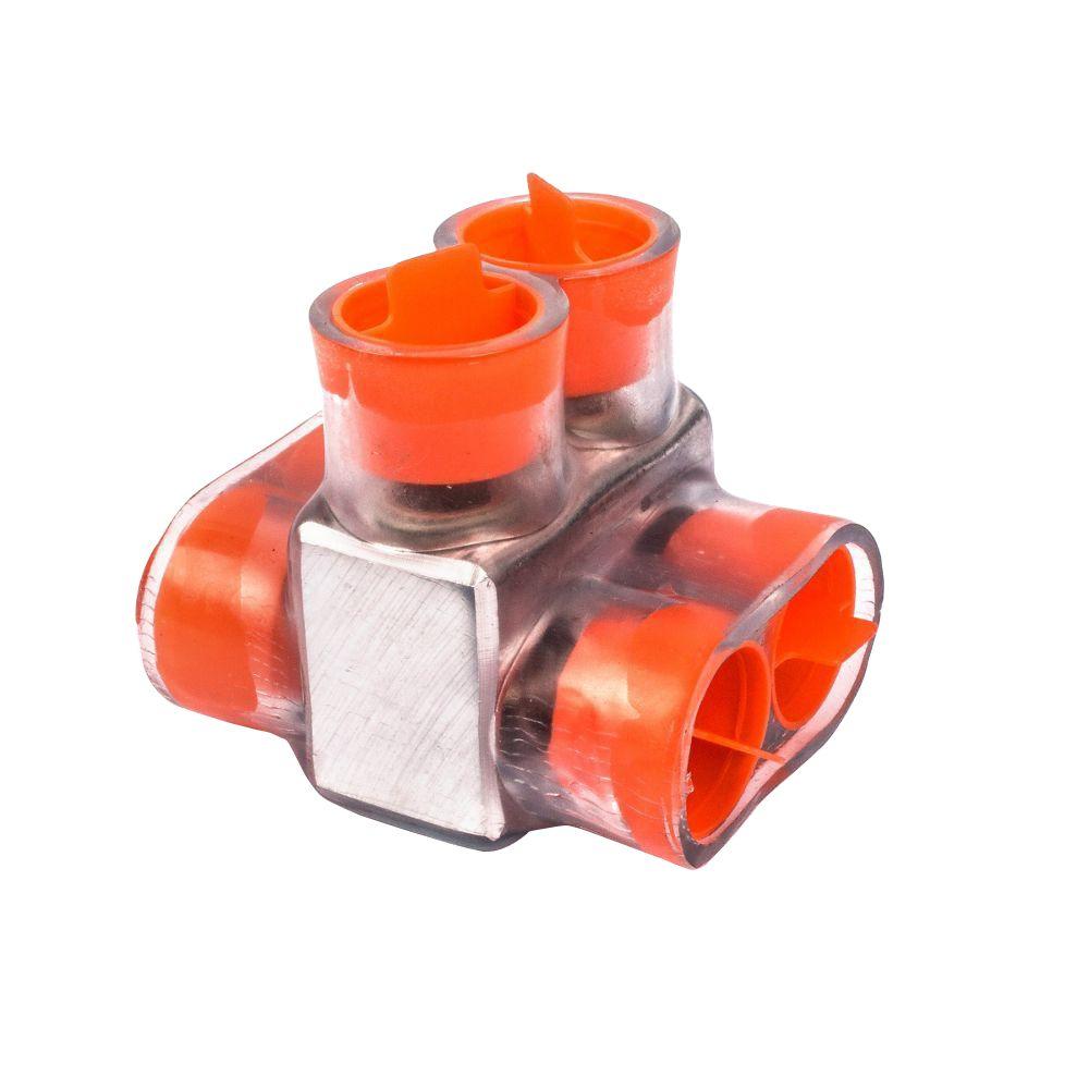
Wire nuts on 6AWG are a bit 'cumbersome' to say the least. You should use a Multi-Tap which is basically a piece of bar stock with set screws and insulation molded around it. Below picture is available at Home Depot. You'll have to see how it all works out for your particular setup, but you might be able to run the 6AWG wires into the "remote little box with 2 breakers" and fit a pair of 6AWG wires in the taps at the top. The 2nd pair run out to the 6-50 outlet and no multi-tap's required. If you can't do something like this, then you'll have to use the multi-tap's as a "T" running 2 wires on one side and one out the other
You can connect the 6AWG to as many loads as you want (hoist directly and 6-50 outlet(s) and sub panel, etc) so long as it's protected upstream by the proper current limiting device (breaker in your case). Similar answer to the question about feeding a 6-50 outlet with 10AWG and a 30A breaker. Since the 30A breaker is appropriate to protect a 10AWG wire from over heating, you can put a 6-50 outlet on it no problem. You just won't be able to use all 50A before tripping the breaker.
It looks like you can put up to seven 6AWG wires in a 1" EMT conduit per the below table. I'm not sure if the 6-3 that you were looking at was solid or stranded, but I would strongly suggest that you go with stranded individual conductors for this application. Also, please run 4 wires so you have both a neutral and ground.

Guys,
I 100% appreciate you posting in this thread that I started and you have great information but I would love it if we kept this thread about the actual lift modifications themselves and less about the specifics about electrical wiring.
I really hesitated posting this message because I really love that everyone is being helpful here but I would just like to keep this thread more about the mods themselves.
Hope you all understand and do not take offense to my comments. Maybe if we started a new thread for the wiring specific stuff and posted a link here in this thread?
Thanks guys. I started this thread 3 years ago and am just delighted to see that there are still folks adding to it. I dont even have a lift yet but am looking forward to adding a bunch of these mods once I get mine.