To avoid these ads, REGISTER NOW!

DIY motorcycle lift.

indisguise

Well-known member
Joined
Sep 15, 2019
Messages
103
Location
Rust Belt....
Hi folks,

I'm a long time "lurker" on this forum and decided to post back to the community. I don't usually post on forums due to the "Arm Chair Critics", however this community seems more respectful. My interests center around restoring/building motorcycles/cars.

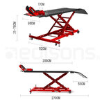
I sketched some designs for a motorcycle lift over the last few years. However life and work constantly got in the way. Luckily some time appeared recently and I decided to commit to this expensive endeavor (blame steel $$$). The design is simple, and the build was more about experience than cost. Honestly it's far cheaper to buy a pre built lift....However I wanted something that could double as an adjustable welding table too.

There were many errors made along the way....

The build started with the raw materials.

050ui0cvyvFsyZ5ct_9kgOKAp3HYlG2KttM=w2006-h1504-no.jpg

A frame was welded and the top sheet metal was cut. This was no easy task as the top is 1/4" steel.

YRETJk2pylXTyMfUM3KDktR1zCjGYi0y6nOgoyOE9OKOV_nKZjVPtmVmnTIr5qgq8fM4fWnM6wUMt6t0wQr0haUmIcmGFRg_31UWNEhbYvXfPCvYEA2QE7JlNkEC_xXcafCNizMhjpEMx4TRzDzj1vb6EsAd6dGCK1SVp8q7DSLq7vOTmXsj2nOTvacK-jp5_udWodsyf_zVfIfBR8YwQkdZ6YYlUPmhjZpzkbCcZi3QB4Hpa8EhI_lu-m_Lz1aFtrPeusagK4r2zRTwEa61Fd5fEQMAsZe2xLEfLRtU-YqIP_ZKiSR4BX9jJIB2t9qOil_-dSrnQ3lVI5Zqws_0tRdT6694hXWhdY7VuOKpnOKXmsqcjppLSmwFh2kK717fyAeljm24KaDFrDERPndcydUsEzJ-95g9TzCrg1SHzhLoCLm4dSudUO8Z6Q5NR1s2mzJVOw20ThNZqJOzHE3lCFoptDDQsqX0X7iT0vSrG7AujOjpQlZ_EoIc0YEdYjbkjnvD2himDn61RR7Y544Mf435Gyza-dgOw2Tr5_KYYlcACNC9gaTMmD3ajIj0C_FcKlFRb8O3ant90_H7hMJEhWhFVO-4k4M8rFYGz4QxWfrQZwDN6a98RfDaaCBQq-CpezzD6rPjFUp6FYUQadGby_8LrP5yOQbzjtRkS3xiNAVq4oPxcGkRAg=w2006-h1504-no


QgHDSvNTz5reOsvQm_i5lTf9q9QJEuNsyko=w2006-h1504-no.jpg

The top is seriously heavy..

2WqTxwNJzwyKLZTzuSm4GTwUXQ5CRmQsBF8=w1128-h1504-no.jpg

The next step was to build the scissor mechanism. The observant will notice a design flaw here...

jV94Yn_Sdjsh3RoTKsRumIb3-VfPXkuiuQs=w2006-h1504-no.jpg

Then this was attached to the top and tested..

mQcdDWffodslDaPK3xlzHn5ofe5HrQUalfs=w2006-h1504-no.jpg

Now it needed a power source....and this is where things went a little OTT.

zVrJSvwFKqvOaTS3aA4XJFZfFEJ5NPINjkg=w2006-h1504-no.jpg

Currently I'm adding the safety lock and then its almost done.

6AOHfddLZDKNyn8jXG_PQdYXZwgWkf6sBpY=w1128-h1504-no.jpg

oFIX_yERcfnpNkTrMWn70bISUIe9LWKxP2Y=w2006-h1504-no.jpg

I will note that the hydraulics are a complete overkill. The 5 tons of pressure from this setup destroys 11guage metal...No failed welds though...and yes that weld is too hot :)

HycgtLE-n5F8h9_TilqICyS--QaQWtMFV6s=w1128-h1504-no.jpg

RUikiZawVnSpOrhEolyEwOsz1QW-0HAD8-Y=w1128-h1504-no.jpg
 
Last edited:
To avoid these ads, REGISTER NOW!

nitroracer20

Well-known member
Joined
Feb 25, 2018
Messages
238
Location
NY
Badass. Are you going to mount the hydraulic “power pack” onto the table somehow?

Going to be a great multi purpose table!
 

bdbecker

ALLIANCE MEMBER
Joined
Nov 18, 2015
Messages
5,543
Location
Iowa
You're giving me bad ideas (I mean that in a good way). I've had my eye out for a used Handy Lift for awhile now, but anything with a fair price sells fast. A DIY lift could be just the ticket.

Looks like a solid start - can't wait to see the rest!
 
OP
I

indisguise

Well-known member
Joined
Sep 15, 2019
Messages
103
Location
Rust Belt....
Small update....

I realized the locking mechanism was in the wrong place...So out with the grinder.... You can see the ratchet strap safety mechanism here. The table would kill me if the hydraulic piston failed.

V0C-76-oMgGM96MZfNyUC20N1lBcZtNpLmA=w1918-h1438-no.jpg


The dual purpose nature of this table was put to good use. Although I have the Miller table behind, which is fantastic, having this dual purpose height adjustable table will be fantastic.

eg01g7VAfNBGkxa_UXbelNyCfUur4JxN7dA=w1918-h1438-no.jpg

Then later changed angles to make the welding easier.

ThbqXeeg1nW6PWFrJmwTAD63VVHARFune8A=w1918-h1438-no.jpg

Now I just need to attach the safety mechanism to the top of the table.

Jfn68fyZ0ZMqK3xUak4WICMR3sSbPP7U1bw=w1918-h1438-no.jpg

Thats all folks...slow and steady.
 
Last edited:
OP
I

indisguise

Well-known member
Joined
Sep 15, 2019
Messages
103
Location
Rust Belt....
The lift is close to being done.

The locking mechanism is in place and the wheel clamp is bolted down. Making a front wheel clamp was not worth the effort as they are peanuts to purchase.

gGWXFWVyp0o5mSJVclwHJx7hInz-opr3oYu5GtUvMnA2n1CS3SBx-iP_25sanwYM_eDpkzNzfriUeyFBcTHhcMC-wf2DIosT5ucxKX0xH_g3iSdEMUmJ17olPcm8jx6guxvPgYJ9ioIGGogy1jYrKhUdVrXMAVOdVauGIxCQCkGCRSz5tWd7VlPS20e1OpTf_e83OLihWw40mUYhc6uDvmwUOD7T1omWKpfubfeYK9lK5ZhhRW-MRjsXt2c1e8FamPPm_REsJYAD82oOaCwacjKX1SIyTRVj_AsuiknBxMnIngveI9taroI9dRumJoyKdhmx418sFjgSX3dvsxVxNz4eqwBSVOBeLzWouJHkQxYbnceqyEEnKYmCyZavHNDnnlqIPYGHSsWvgZ_-IJ70M3xMzhoXd1v4uB3as7pwqzqjMVP4BilIGt4wrA01aa20FBtpvbJUeKYVUnYf_tIdCyHytHuAce27dn9lGQPlTl9meDWPREZpOH3ewzkl73VK4z8HFKDSphKqSk-bhSzQpapRoA2jzuZqECQhnvjFhgg7azFcZkgeqltlzlzf37YOJ4q7nhaOD6PIFj7NNb26YVmTTBvnemA1i-RTucbvEl_-zzmKrLxg4D0ejXtb9zD7akABmECJtBkagFQXp6ZBPX3Ub7CyKjgPiSOolF6I3rN03chylQajkDW30s5pbKN2AHxdczx1tjImLCRvmMmRi8-Z7Q0VDxUXwkimZOJDHZdWXGpT3gtXJg=w1892-h1418-no


akxkvJauWOtmsuP4wgCFOU2wiiciMYeUkCjfRdmz8ZJyngZE6z7IHf7ZYrCmSkoWJ_Q7JU-X0CHVeJtZwjjsCjbJQBwVOiEtK-qBmXPXNRr3Cw4eamUMdR4OdWvkh-MGlHtOJXvV7Vn0tUvNiXQZiCgHAPbSS9KbOfgkHYMFVqWG9zwe7glaa9cEgAC60dJHYY3jrMMU-oPPySAlmYBVtGwog50T7NiQxXLKTtA7mG2XHgImxK7qU3EkOkTEvqywxkwJsg5BNwL2AiUduGuls8r9rwQdxtit4VCEjsTVbZxpjQEkJ4_AlGrNwh5FXq0qkSINVNBvd7xDC_jdqOZxCZveVplio31OcmiELaHDugR1Vreu-KicjrzzgfLQKzdq05AUftEN2kDFU-gVXNTBPTDEib3gKz3XHBUL2CDm7ijC6ct_ZZ-oRpCH9X9IagHATXQg2ROIBAcRI_JHKGLtyUtwm5vQBlPwJdXOrVZeblCyct2qdLuxyNX4wDnM_6b7846-97ihoi7VS8Ozq4yZHVUP3tMXQQU8_Ic7HXZveEtb0neLcamxiHRE9nBERUg5O_PLfLLVPe661io2tp65WiMqp6EUN67qwZAxfzw-bWVIFYIPsG4nPPRfu-fb_dctYoaxS_UYu3sOeCoOKajret8ZVBCqk7_6xX49xGhg3LLHFPAA_ZvL-PumZiGP=w1064-h1418-no
 
OP
I

indisguise

Well-known member
Joined
Sep 15, 2019
Messages
103
Location
Rust Belt....
Eventually Yes. The plan would be to remove the lower mounting assembly from the lift. However todo this safely I need purchase an engine hoist. Repairing this "in-situ" is not a fun proposition. The hoist will allow me to dismantle the entire assembly.

Luckily the lift is completely operable as is... and it can function until an appropriate hoist is purchased.
 
OP
I

indisguise

Well-known member
Joined
Sep 15, 2019
Messages
103
Location
Rust Belt....
As suggested by firebrick43, the damage was removed and a new re-enforced mount was added.

You will also notice a slight change to the design. The ground wheels changed location. This stops the jerking action from the hydraulics.

The bent tube was replaced too..

The photos will work soon. Sharing images from photos.google.com is always a chore

XgzQYD7JnvvGl5C-SZepVGkfctGmr9n6cBg=w1134-h1510-no.jpg

05s6E90GlHMnPir8FCpI-pFr-0H3ysrYgnA=w1124-h1498-no.jpg

There are a few more small jobs and then the lift is just about complete.

And now my new toy awaits.....A southbound Heavy 10L.

gS5pbAh2MqiIlEFygUZVOvj4gtB1XdEK4Fg=w2014-h1510-no.jpg
 
Last edited:

alfazer

Well-known member
Joined
Nov 1, 2011
Messages
393
Location
N. Ireland
I like this design with the criss cross scissor legs a lot more than the ones with the parallel legs. They take up less room and lift straight up. In Europe at least, most of the cheaper lifts are parallel. (I say Europe, but I'm guessing they are from China.) This type like yours looks a lot more like a professional lift.

Anyway, I was thinking of building one like yours but I would like to try using a long screw placed horizontally at top or bottom, pulling the two halves of the scissor together to provide the lifting instead of hydraulics. I could drive it with a impact driver.
 

andyvh1959

Well-known member
Joined
Feb 15, 2020
Messages
2,590
Location
Green Bay WI
Nice build. What is your source for hydraulic power? Enerpac? Electric over hydraulic? Air over hydraulic? If you don't have a power source already, then the Enerpac air over hydraulic power unit is probably the least cost. Not very fast for certain, but it will develop 3,000 psi easily with a good 90 psi air source.
 
OP
I

indisguise

Well-known member
Joined
Sep 15, 2019
Messages
103
Location
Rust Belt....
@DYNO-DAVE Good question. The hydraulic cylinder is rated at 5 tons. However the weakest link is the 11 gauge steel tubing for the legs. I really wanted to use 2x3....but that was unavailable. The table itself is incredibly heavy...so in total I hoping for 2000lbs..at some point I will do some actual math.

@alfazer, the long screw mechanism was tried...It was really cumbersome with a table of this weight. Here is the "moc-up". Also my design was terrible...

MgYkOmuWSOE1J7wnqk0TiMllwmdjIEYk2Bw=w1998-h1498-no.jpg

@andyvh1959 The power source was a cheap eBay dump truck power unit. Honestly its too aggressive (and was too fast!) and I'm tuning the flow with a needle valve.

ygCIKbi5ERfXLQBDgBdHVYtegkkCDcH-dMw=w1124-h1498-no.jpg

The lift is now operational and got this beast running for the season.

TkiFTAGARk3NjHBK7dhE6HZW7W5nw25ADpA=w1998-h1498-no.jpg
 
Last edited:
To avoid these ads, REGISTER NOW!

andyvh1959

Well-known member
Joined
Feb 15, 2020
Messages
2,590
Location
Green Bay WI
Another way to "tune" the speed, especially on descent, is to install a orifice disc (think of a washer with a tiny ID) into one of the fittings. But a needle valve will certainly work and easy to plumb in the circuit.
 

alfazer

Well-known member
Joined
Nov 1, 2011
Messages
393
Location
N. Ireland
@alfazer, the long screw mechanism was tried...It was really cumbersome with a table of this weight. Here is the "moc-up". Also my design was terrible...

I was thinking it would have the threaded rod just peeping out the end of the frame and has a nut welded on it and a washer running free. The rod spins but doesn't move longitudinally. Further inboard, one pair of the scissor legs has a crossmember with a nut mounted in it that can swivel through an angle but not spin. This is what does the travelling along the threaded rod.

(I can draw better than write explanations)
 
OP
I

indisguise

Well-known member
Joined
Sep 15, 2019
Messages
103
Location
Rust Belt....
So those following the Motorcycle Build thread would know I moved several times since building this beast. The most recent move provided a wonderful work space in the forest. Unfortunately the moisture from humidity has wrecked the lift and I am clearly regretting the decision to leave it unpainted.

Lift.jpg

So there's only one thing todo. Fix the rust and fix all the issues. When I first built this, I was in rush. In hindsight I wish I had fixed all the issues there and then. However life is rarely like that. So let's move on....

The issues are:
  1. One leg is very bent from the cylinder. This is due to the incorrect angle at its lowest point. Most cylinders need a little more that 15 degrees incline at their lowest point. If you fail the cylinder will just bend the metal....8 tonnes does damage!
    1. See image here. I tried to fix it (read "bodge")... so time to trash this entire leg.
    2. Rust2.jpg
  2. The rust is out of control.
  3. Stiffen the bent leg by rebuilding with 3x1 steel. This was the original intention however the place in WA was out.
  4. The Cylinder placement is completely wrong.
  5. The lack of sleeving on the pivot points causes binding on the way down.
I first removed the good support leg to allow me to wire brush the rust. Hate this task...

Good-support.jpg

The second was trashed and the good metal was harvested (metal is getting $$$)

sparemetal.jpg

This leaves me with the components for reuse.

Post-Grind.jpg

Next I need to purchase some new 3x1 metal and start rebuilding.
 

crazylunker

Well-known member
Joined
Sep 2, 2014
Messages
198
Location
Connecticut, Trumbull
I love it, I built one about 25 years ago when the chopper thing was taking off and was doing some fab work on the side. I used an angle cylinder and the OTC air over hydraulic pump from my tubing bender. I added a 1 way flow control to slow down the descent. initially like you I was trial and error and actually never finished it but have been using it since I built it. I can add some pics and dimensions if anyone is interested.
 

Gwrskien

Member
Joined
Jul 22, 2021
Messages
5
Hello, nice build. Make shure you get the weight distribution correct when the lift is raised.. it looks like you have the "x" lift mechanism sentered, and when you lift the bike, as the "lift rollers" move towards center, a lot of the weight will "hang behind the middle of the X". The lifts i have seen has the fixed point of the "x" where you drive on to the lift, and the front wheel clamp will "hang in front of the X". The rear of the bike will then allways have full support.
 

Attachments

  • measurement-gallery_1_15.jpg
    measurement-gallery_1_15.jpg
    88.8 KB · Views: 74
OP
I

indisguise

Well-known member
Joined
Sep 15, 2019
Messages
103
Location
Rust Belt....
The weight distribution comment is a very good one.. and yes its worth moving this further back. I was somewhat lucky since the lift is incredibly heavy due to the 1/4" top. However why not take this opportunity to fix things.
 

whateg01

Well-known member
Joined
Mar 13, 2006
Messages
11,191
Location
doo dah, kansas, usa
Your mounting points for the cylinder would be stronger with better triangulation. Instead of short gussets and relying on the tube's natural strength, a longer piece going directly from the cylinder mounting point to a corner would be far stronger
 

ChefRex

Well-known member
Joined
Jun 1, 2020
Messages
3,693
Location
NJ
Hello, nice build. Make shure you get the weight distribution correct when the lift is raised.. it looks like you have the "x" lift mechanism sentered, and when you lift the bike, as the "lift rollers" move towards center, a lot of the weight will "hang behind the middle of the X". The lifts i have seen has the fixed point of the "x" where you drive on to the lift, and the front wheel clamp will "hang in front of the X". The rear of the bike will then allways have full support.
The K&L lifts I have at work the fixed point is at the front.
 
OP
I

indisguise

Well-known member
Joined
Sep 15, 2019
Messages
103
Location
Rust Belt....
Your mounting points for the cylinder would be stronger with better triangulation.
Not only that, if you look at my initial attempt, the orientation of the tube was completely wrong.

WRT:

it looks like you have the "x" lift mechanism sentered, and when you lift the bike, as the "lift rollers" move towards center, a lot of the weight will "hang behind the middle of the X".

Lifts which are not anchored at the base, like mine, are sometimes centered too (see picture). It really depends on where the center of mass is located when the bike is on the lift. Once completed I will do some actual calculations.
Screen-Shot-2022-08-28-at-7-55-22-AM.png

I decided to throw a few hours at Fusion 360 to see the movement. While I normally hate using computers outside of my day job, I decided the experience gained doing this was worthwhile. The learning curve was fairly steep.


whateg01

Well-known member
Joined
Mar 13, 2006
Messages
11,191
Location
doo dah, kansas, usa
Not only that, if you look at my initial attempt, the orientation of the tube was completely wrong.

WRT:


Lifts which are not anchored at the base, like mine, are sometimes centered too (see picture). It really depends on where the center of mass is located when the bike is on the lift. Once completed I will do some actual calculations.
Screen-Shot-2022-08-28-at-7-55-22-AM.png
The lift pictures has the legs centered when the bike is in the air. Your design appears to have the legs centered when it is lowered but when in the air, the support is no longer centered. I believe that is what Gwrskien is saying. I'm the photo of the red one, the support appears to be off center but because it's all tied together with the long base, it is actually fully supported end to end even when it's in the air.
 

Gwrskien

Member
Joined
Jul 22, 2021
Messages
5
I bought one of those Diy Dxf files for a welding table, the one with all the holes, and was thinking of a lift system as legs for it. I would end up with one end hanging with less support than the other if i did the X lift. If i put a car chassie with a v8 on top, that would not have been good i think, so that is why i made the comment about the weight having less support as you go up. My table is 2m x 1m ( 80x40 inch), so the "arm" can get big.
 
OP
I

indisguise

Well-known member
Joined
Sep 15, 2019
Messages
103
Location
Rust Belt....
@Gwrskien all good input and I will check the math on the center point. I do remember doing this math. More than likely my "rushed" CAD work is wrong and the actual lift is correct LOL.

OK back to it.... This is just a quick update on progress....

First I needed to remove some rust from a few tools. Its humid here in the midwest and this was prior to the installation of a dehumidifier...
Evapo-Rust seems to work really well IMHO.

tools.jpg

tools2.jpg


Onto the lift. As mentioned previously, I failed to sleeve all the pivot points on the previous version. This resulted in binding and sticking when lowering the lift. I took the time to do the pivots correctly on the second attempt. Its been a while since I last welded and it clearly shows. I need a lot more seat time as one weld was too cold with bad penetration and the other was inconsistent....

welding.jpgwelds.jpg


With the sleeves completed and the legs tacked in place it was time to test everything. Note I'm using the smaller bolts here while I wait for the 5/8" grade 8 bolts on order.

test.jpg

Since everything looked good, I moved onto installing the wheels. The wheel installation has also changed. This time I'm using small stub axles to mount the wheels. You will notice that I changed the tube orientation for this lower support. This is where the cylinder connects and I need to take advantage of the strongest orientation.

orientation.jpg

The tubes were also curved to match the wheels.

wheel.jpg
Not a huge update and not overly interesting but progress all the same. On another note...the new garage needs a lot of work. I need to understand flow and what works where as its already a complete mess.....

mess.jpg
 
Last edited:
OP
I

indisguise

Well-known member
Joined
Sep 15, 2019
Messages
103
Location
Rust Belt....
The lift is slowly coming together. The lack of photos is due to some technical challenges faced which caused me to focus on problem solving rather than content. Sorry folks.

My ability to maintain a decent weld pool was variable and I need to clean parts more thoroughly. This is evident in the shot below.

IMG-1138.jpg

I found a working cylinder angle after numerous attempts to move the hydraulic cylinder, without buying a new proper sized unit. Heres me testing level.

IMG-1215.jpg

And finally the lift in its 99% percent finished state.

IMG-1269.jpg

I still need to:
  1. Install the hydraulic needle valve as the speed is still aggressive..See the movie below.
  2. Install the feet pads by the ground wheels.
  3. Build some leveling feet.
Once this is done I will re-test with some weight to see how it operates. It is definitely smoother and and the overall operation seems decent.


chuck356

Well-known member
Joined
Jun 17, 2018
Messages
48
Location
east-central Illinois
Good on the 1/4" thick top, I've had several Handy lifts (had a bike shop for 40 years) and the tops on those always bent. And the Handy is known to be as heavy duty as you can buy. Those Harbor Freight ones are scary, very narrow.
 

ronr80

Well-known member
Joined
Feb 13, 2013
Messages
504
Location
ontario
very nice I love these home projects I'm always looking for something to cut,weld,build .
 
To avoid these ads, REGISTER NOW!
Top Bottom