To avoid these ads, REGISTER NOW!

Milling Aluminum on MillDrill Speed Feed Advice Needed

2oolhound

Well-known member
Joined
Dec 18, 2010
Messages
5,918
Location
BC Canada
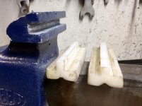
I bought a Reed 104 1/2 with plastic jaws which I dislike so I don't use the vise which I really like. I decided to make some aluminum jaws for it so I can get some use out of it. They are the "T" shaped jaws. I recently bought a 25 year old Rong Fu mill drill and have zero experience milling. Speeds go up to 2500 rpm's.

attachment.php


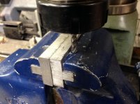
I'm using 6061 flat bar 1' X 1 1/2".
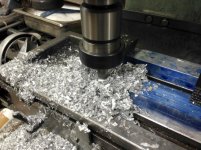
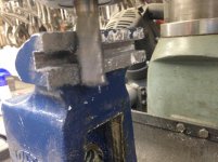
I'm using an 11/16" end mill and taking a 9/16" wide by 1/2" deep swath off one side of the bar in one swipe. Speed is set at 440 RPM's and it is going slow. It's taken a good 1/2 hour to do the 1st cut of 5" length. If I feed faster I get vibrations and jitter. I'm using a few drops of aluminum cutting fluid on the top but I don't know if it makes it down the end mill to the cutting area.

attachment.php


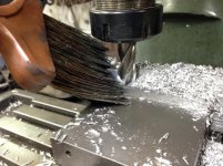
I started off brushing all the chips away regularly but the last half I just let them pile up. When I got done and cleared the chips you can see how rough the side edge looks on the last half. I'm thinking chips were falling into the cutting area or it was getting hot but there were no signs of excessive heat. The end mill looks good still with no deterioration easily visible on quick inspection. I'm thinking I should pick up the speed to maybe double (at 440 now so around 900 rpms. Should I have been doing this in 2 passes (same depth but only 1/2 as far in)? I see the very edge is just rolling up along the edge.

attachment.php


Any tips or advice is appreciated!
 

Attachments

  • ReedPlastiJaws_5693.jpg
    ReedPlastiJaws_5693.jpg
    73 KB · Views: 287
  • ReedAluJaws_5684 copy.jpg
    ReedAluJaws_5684 copy.jpg
    121 KB · Views: 289
  • ReedAluJaws_5688.jpg
    ReedAluJaws_5688.jpg
    112.2 KB · Views: 291
To avoid these ads, REGISTER NOW!

cvairwerks

Well-known member
Joined
Aug 12, 2016
Messages
7,255
Location
Within hearing distance of Texas Motor Speedway
6061 should be cut around 280 SFM with a feed rate of about 12 FPM for a two flute cutter. For a 3/8 “ diameter cutter, that would mean 3000+ rpm. The amount of material being removed at a 9/16” DoC, should be down in the range of .060” for that mill. You’re trying to hog out material at rates appropriate for a 20 hp VMC and not the machine you have.
 

BukitCase

Well-known member
Joined
Apr 11, 2017
Messages
1,075
Location
Oregon
I don't do much aluminum, but go to google play store and search for FSWizard. It lists 6061 aluminum plus tons more metals, hss/HSCobalt/Carbide/Diamond and ceramic tools,9 different tool shapes, 8 different tool coatings + none, + a bunch of other choices... Steve
 

matt_i

Well-known member
Joined
Mar 14, 2008
Messages
10,744
Location
SE Michigan
That's a pretty big cut to take at once. I would probably do that cut at 200 rpms.

I think you are correct that you were "recutting" chips in the 2nd half and some by nature get smashed into the clean surface. My opinion is that being severely cold worked in the "swarf" state they are a lot stronger than the base material and thus "damage the softer part"

The power of the endmill is on the spiral "side" of it and not the bottom. The sharp corner is the weakest part of the tool. That said, I would keep your 440 rpms and take a cut of full Z depth but 1/16" from the side and keep feeding sideways (Y) into the cut until full depth. Often its desireable to rough to the dimension where you can take a finish cut in both Y and Z with roughly .005" taken off each.

Just some other comments, it looks like a lot of stickout on the spindle. If you can chuck the milling cutter directly (does it use R8s?) that will be better. Also I recommend a Kurt or a knockoff Kurt is also a good way to speed up setups. Also as you buy cutters, a 2 flute puts less pressure on the machine and material. (each flute has its own "chip load" which is additive for the number of flutes in the cut) So 2s would be better a you go into steel cutting. And no problem with a 2 flute in AL. I find the double-end to be a good value plus if things go bad there's always a fresh side with a flip.

Project is looking good and I think you'll really like the outcome in the vise :thumbup:
 
Last edited:

B.S.A. (ret.)

Well-known member
Joined
Mar 3, 2017
Messages
416
Location
Central Connecticut
All good advice given above. That is a large cut for what you're using. Another technique to avoid is "climb milling". You want to have the cutter throw the chips in front of the path of the cutter, rather than have the cutter "pull" into the cut and try to "climb" through the workpiece. I agree with Matt_i regarding the "overhang" or "stickout" as he describes it. the more support that the cutter has (i.e., the closer it is to the quill), the more rigid and stable your set-up is. Take many smaller cuts and follow up with a "finish" cut or two at a higher speed. Ordinary kerosene works well as a cutting fluid for aluminum if you have good ventilation and don't mind the smell. As was mentioned above, take your time using lighter cuts and more of them. Get rid of that toolholder and invest in a set of collets. Good luck!
 

mowkep

Well-known member
Joined
May 7, 2017
Messages
471
Location
Stow, Ohio
Surprised you didn't gall the end mill. Cutting oil would help also. Advice above is good. Multiple smaller passes, shorten that spindle...etc
 

larry_g

Well-known member
Joined
Apr 28, 2007
Messages
16,893
Location
oregon
Another item to help you succeed is to lock all axis that are not moving. That means lock the quill lock and the Y axis lock. Have you gone through the machine and adjusted up all the gibs to zero clearance? Another thing that will help on a small underpowered mill is to use a roughing bit. Some call it a corncob bit. They take many small cuts vs one big one. You can also hold the nozzle of your vacuum cleaner in there to **** up the chips to prevent recutting. All small things that help one make a successful cut.

What I have said is in addition to advise given in other posts above. I can also recommend the black book, https://www.engineersblackbook.com/ Well worth the money.

lg
no neat sig line
 

exmaxima1

Well-known member
Joined
Jun 25, 2011
Messages
6,343
Location
Midwest
In summary, faster spindle speed, less cut per pass, occasional spray of coolant (not cutting oil), and use a 2 flute bit. I machine 6061 alum almost exclusively on an old Bridgeport mill and could make a 1/16" deep pass that wide in less than 30 secs. 6061 cuts fast and clean, unlike 6063 or godawful 3003. Clearly the chips are the issue.
 
Last edited:

BTL-A4

Well-known member
Joined
Feb 28, 2018
Messages
1,255
Location
Santa Clarita
I took a machining class recently. I was brushing up to teach an Engineering class. Here are some formulas that could be of use to you:
RPM=Cutting speed x 3.82/cutter diameter

The cutting speed given for aluminum (not sure what type) is 400 with a HSS cutter. So:
RPM=400 x 3.82/.6875 is 2,222 RPM. I think this assumes a cutting depth of about 0.025".

chip load=feed rate (in/min)/RPM x number of flutes. So:
Feed Rate= RPM x no of flutes x chip load.
The chip load for aluminum is given as .007. Again, not sure what type of aluminum.
Plug in the numbers: 2222 x 2 x .007=31 inches per minute, which is about 1/2" per second.

Keep in mind that this is from an adult school class. We had a chart in class that had the values given above. We were told to take no more than 0.025" off in a pass. We had big Bridgeport machines with Kurt-style vises.

It wouldn't hurt to go slower. These numbers seem really high to me.

I've been told WD-40 is a good lubricant for cutting aluminum.

Please get a vise! The way you are clamping is dangerous, especially when you take off so much material.

There is lots of info on Rong Fu mills and their clones. They have unique issues and characteristics. Hobby-machinist.com is a great place for info. I encourage you to join.
 

matt_i

Well-known member
Joined
Mar 14, 2008
Messages
10,744
Location
SE Michigan
The cutting speed given for aluminum (not sure what type) is 400 with a HSS cutter. So:
RPM=400 x 3.82/.6875 is 2,222 RPM.

If you buy your own edge tooling you'll probably want to choose a lower speed. Because you will have to buy far less of it. Speed creates heat and ultimately the sharp thin edge can't handle it.

Imo, and its just mine, most stuff on a full sized bridgeport can happen at 500 rpm....or lower.

Also imo the "tabulated" cutting speeds were Industrial Engineer stuff for figuring out how many parts could be made per hour/shift/day.
 
OP
2

2oolhound

Well-known member
Joined
Dec 18, 2010
Messages
5,918
Location
BC Canada
Thanks all for the excellent info. I have a really bad internet connection so haven't been able to get back on line till now.

Before I had the Rong Fu I bought about 50-60 end mills knowing I was going to get some type of mill eventually so my end mills are just what I have on hand. I will try some thinner ones. I think I've seen youtube videos of mills cutting slots the way I've tried this but I guess they were much more capable mills. I am using collets in a collet adapter I got with the mill. I hope by the time I ruin my end mills I'll have learned a great deal about milling metal ;).

I'll post more results as I get a chance to proceed (and get back on line) but thanks all for this valuable info!
 

mowkep

Well-known member
Joined
May 7, 2017
Messages
471
Location
Stow, Ohio
In summary, faster spindle speed, less cut per pass, occasional spray of coolant (not cutting oil), and use a 2 flute bit. I machine 6061 alum almost exclusively on an old Bridgeport mill and could make a 1/16" deep pass that wide in less than 30 secs. 6061 cuts fast and clean, unlike 6063 or godawful 3003. Clearly the chips are the issue.

I've been a machinist for 30+ years. Yes, coolant is preferred but I suggested cutting oil because it is probably more readily available. It is stinky and smokey but something is better than nothing. I used a coolant spray mister when I machined torpedo vane forgings. That was the sh!t.
 

cvairwerks

Well-known member
Joined
Aug 12, 2016
Messages
7,255
Location
Within hearing distance of Texas Motor Speedway
We used to use flood coolant when hogging out some data chassis parts. It was cheaper and faster for us to hog out a 3" wide, 4" deep and 6" long pocket than to bend and rivet them from sheet metal. We got probably 200 cutoffs from another part of our operation to use. 6061T6 6" thick stock.... Our guys could throw a block on the Maho and launch it while working on other stuff. Took about 40 minutes, three tool changes and then flip it 3 more times for other operations and it was done.
 

zmotorsports

ALLIANCE MEMBER
Joined
Oct 20, 2009
Messages
21,454
Location
Northern Utah
I use the formula of aluminum being around 250~ish SFPM and times x 4 then divide by cutter diameter.

250 x 4= 1000, then divide by .6875 = 1450 RPM for that 11/16" end mill. That is a lot of depth you're cutting though.

I would cut that one of two ways. First take lesser cut and feed across in multiple passes OR stay off of your final dimensions by about .020" and plunge cut along the length then go back and take a clean up cut to the correct dimensions.

But I'm not a machinist.:beer:
 
To avoid these ads, REGISTER NOW!

mowkep

Well-known member
Joined
May 7, 2017
Messages
471
Location
Stow, Ohio
I've had tooling guys come in with some ridiculous expectations. Others knew what their tools could do to a t. I had a guy from IMCO end mills having me fly through some rails with pockets. This was cut 2x3 pockets probably .5 deep. This was also dry machining with a 1/2 end mill in steel. Another job, I was trepanning 3" circles in two stacked long magnesium plates. He wanted a ridiculous feed rate. After we snapped the first end mill....he was like "that's too fast". It's all relative.
 
OP
2

2oolhound

Well-known member
Joined
Dec 18, 2010
Messages
5,918
Location
BC Canada
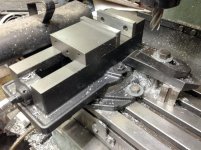
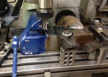
So I used most of the above advice and got it done. I used the same end mill but just took 1/2 the width needed followed by a second pass to the line and then a third final pass to depth (about the final 1/8"). It cut much faster and smooth. I constantly cleared the chips away from the cutting surface.

attachment.php


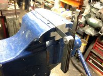
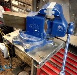
Also, following the advise above I used the vise I got with the machine. It is a rotating vise and I promptly stripped one of the 3/8" locking fasteners for the rotation ring. Don't you hate it when in the middle of a job something pops up requiring you to attend to it and side line your primary job. Actually I haven't dealt with the stripped fastener, I just used a hold down clamp on the rotator ring to lock it and finished cutting the jaws.

attachment.php


Speaking of getting side tracked, 1st thing I did was drag out an old table saw someone gifted me to put a carbide blade on and try hogging out most of the aluminum so I could just finish on the mill drill. It was corroded up pretty bad but got it freed up only to find the motor was thrashed. I swapped the motor for one I had and after cutting a piece of the 6061 length ways I got cold feet and decided that was a dangerous way to do it. I did it all on the mill but later I used the table saw with the carbide blade to cut a piece of 1/4" steel to use as a base for the Reed. It worked like a hot dam.

attachment.php


In my small shop I don't have room to mount the Reed so I had to remove my Wilton bullet. I've heard if you remove a Wilton from your bench and stash it somewhere out of the way it will start wilton. I hate the thought of getting rid of any of my vises so I'll have to get it back in service before it can start wilton.

attachment.php


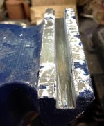
What I discovered was under the primer and blue paint the jaw faces were pretty banged up. This is a photo after clearing the paint off and running a file over the top edge to remove the burrs that stuck up.

attachment.php


This roughness caused my new inserts to not seat 100% everywhere like it would have on a new vise. I can get a .010" feeler gauge behind my inserts in a few spots.

attachment.php


I think I'm going to mix some JB Weld epoxy and use it to fill these 3 areas when I install the jaws and drill the locating pins. The jaws inserts are a nice tight fit and needed to be tapped into place with a hammer. I can use the vise like this before drilling the locating pins but I don't think they will seat any better than they are now. I'll need JB Weld to fill in those few low spots.

Thanks You ALL for the advise and info and feel free to add more thoughts or ideas.
 

Attachments

  • ReedJaws_5723.jpg
    ReedJaws_5723.jpg
    62.1 KB · Views: 127
  • ReedJaws_5713.jpg
    ReedJaws_5713.jpg
    49.6 KB · Views: 127
  • ReedJawsSm_5727.jpg
    ReedJawsSm_5727.jpg
    91 KB · Views: 131
  • ReedJaws_5726.jpg
    ReedJaws_5726.jpg
    62.3 KB · Views: 125
  • ReedJaws_5708.jpg
    ReedJaws_5708.jpg
    71 KB · Views: 126
  • ReedJaws_5698.jpg
    ReedJaws_5698.jpg
    63.4 KB · Views: 125

BTL-A4

Well-known member
Joined
Feb 28, 2018
Messages
1,255
Location
Santa Clarita
"...it will start Wilton"? Groan! So bad and so funny.

If you are going to use a table saw to cut metal, get the right blade. I have a blade for non-ferrous metal that works great. I've cut 1/8" thick and smaller. There are also blades for steel. Much safer.

Could you clean up the paint more on the vise jaws and get the surface smooth? Maybe even use the mill.
 

matt_i

Well-known member
Joined
Mar 14, 2008
Messages
10,744
Location
SE Michigan
Personally I don't think the ~5ksi epoxy is a good fit for the ~30ksi aluminum or ~60ksi ductile iron when you are trying to squeeze something tightly as a vise is sometimes called to do.

I would put those parts back in the mill, indicate, and remove .010" from the face that's preventing it from seating (likely the back tongue or the lower face).
 
OP
2

2oolhound

Well-known member
Joined
Dec 18, 2010
Messages
5,918
Location
BC Canada
Man you guys are tough. Glad I don't work for you. Let me remind you this is the 1st mill I've ever touched, I'm still just getting my feet wet. I was so proud of my progress I popped a few buttons off my chest when I went into the shop this morning. I was calling it done but you're all seeking perfection. Well the thing I've liked most about the Reed vise is how nicely finished the slide is and how tight it fits in the body of the static jaw so I can see where you're coming from.

This morning I took a look at the vise to see what stripped. Does it look like a copy of a Kurt? Ha Ha.

attachment.php


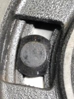
I figure I was torquing to about 25 ft lbs when it went but maybe it was already gone from the previous owner. I scrounged around and found a few flange bolts. Original size was the metric size just under 3/8" but I found a 7/16" was perfect with no binding anywhere. The bolt to the left is what I started with to make the center bolt. The original is on the right.

attachment.php


.............................Original bolt........................New bolt
Length of head.........- .950" .............................. - .860
Width of head.......... - .660 ............................... - .740

So my new one doesn't have the length where it seats on the track but it's tighter along the sides.

Here is the original and you can see there's a 1/16" on the one side and a bit on the left side too.

attachment.php


Here is the new 7/16" and although it is fairly snug the vise rotates smoothly. (the actual flange almost touches on both sides)

attachment.php


Lastly I shaved .008 off each surface of the nut so I can use the same socket or wrench on both sides as I didn't have a 2nd flange bolt to replace the other one. (I ground too much off the extra one I had in the beginning)

attachment.php


I'm going to sleep on the idea of trimming .010 off the face of that jaw. I've already started a new project that is all over my bench right now but we'll see.
 

Attachments

  • RotoryVise_5750.jpg
    RotoryVise_5750.jpg
    51.1 KB · Views: 88
  • RotoryVise_5748.jpg
    RotoryVise_5748.jpg
    107.9 KB · Views: 91
  • RotoryVise_5746.jpg
    RotoryVise_5746.jpg
    111.5 KB · Views: 90
  • RotoryVise_5743.jpg
    RotoryVise_5743.jpg
    32.8 KB · Views: 89
  • RotoryVise_5734.jpg
    RotoryVise_5734.jpg
    59.9 KB · Views: 89
OP
2

2oolhound

Well-known member
Joined
Dec 18, 2010
Messages
5,918
Location
BC Canada
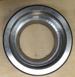
The other issue I was dealing with was the collet adapter kit I got with the mill drill. From day one I knew something was haywire with it because you couldn't screw the clamping nut on very far.

attachment.php


The long taper fits tightly into the adapter so it is held squarely in there but the small taper at the bottom of the collet wasn't contacting the clamping nut evenly even though there was enough thread on the nut to keep the long taper seated.

attachment.php


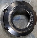
Looking into the nut you can see a concentric ring before the taper where the lower collet taper seats. When I first saw this I knew it didn't look right but everything was so new to me I used it as is and the previous owner had used about 3 of the collets in the kit as well. I actually did some work on a different vise previous to the Reed but have always been leery of the fit of the clamping nut wondering why it only thread on a few threads when there was 3/4" of threads there. In the next pic the center darker ring is the bottom taper the lower collet taper should seat to but the bright concentric ring in front of it blocks the collet from seating there. Where the collet would contact the concentric ring (on one side) would be enough to hold the collet up into the adapter and seat the main taper.

attachment.php


So I finally fixed this in my lathe by machining out the concentric ring (a poorly machined inner flange that never should have sold like this because it was faulty.

attachment.php


Now The clamping nut seats against the lower taper on the collet and threads way up the adapter.

attachment.php


Amazing they sold it like that. Between the buttery threads on the vise and this I'm a little leery although both those items I think are much newer than my 30 year old machine.

Thanks matt and BTL-A4 and I'll check around for so steel cutting blades for that table saw.
 

Attachments

  • RF30ColletSyst_5780.jpg
    RF30ColletSyst_5780.jpg
    44.3 KB · Views: 72
  • RF30ColletSyst_5778.jpg
    RF30ColletSyst_5778.jpg
    34.1 KB · Views: 73
  • RF30ColletSyst_5760.jpg
    RF30ColletSyst_5760.jpg
    40.4 KB · Views: 73
  • RF30ColletSyst_5786.jpg
    RF30ColletSyst_5786.jpg
    37.7 KB · Views: 74
  • RF30ColletSyst_5763.jpg
    RF30ColletSyst_5763.jpg
    48.8 KB · Views: 73

matt_i

Well-known member
Joined
Mar 14, 2008
Messages
10,744
Location
SE Michigan
Good fix on the vise. If you eventually get farther, those knockoff Kurts make excellent drill press vises, but will take you pretty far on a milling machine too.

I havent used ER-40 but have used a lot of ER32 and ER-16.

On those systems you have to snap the collet into the nut first, using the groove as a retainer, otherwise it deforms the collet and eventually it damages the collet if one goes far enough by loading it non-centrically. After the two are mated then you can insert the edge tool and it all tightens concentrically.

I think you machined off the partial "snap ring" that engages the groove. I think it will work but you don't have any extraction (pull out ability using the threads) now.

But you can buy another one, its not the end of anything super expensive.
 

zmotorsports

ALLIANCE MEMBER
Joined
Oct 20, 2009
Messages
21,454
Location
Northern Utah
Good save on the vise, however, unless you plan on doing a lot of angle cuts I would remove the swivel base altogether and only use it when/if you need it. I prefer to mount my vise directly to the mill table. That removes one more area for play and also gives your mill a little more working space or larger work envelope not having that swivel base in the way.

Just a thought.
 

larry_g

Well-known member
Joined
Apr 28, 2007
Messages
16,893
Location
oregon
Good save on the vise, however, unless you plan on doing a lot of angle cuts I would remove the swivel base altogether and only use it when/if you need it. I prefer to mount my vise directly to the mill table. That removes one more area for play and also gives your mill a little more working space or larger work envelope not having that swivel base in the way.

Just a thought.

I'm with Mike here. Set aside the swivel adapter until you need to cut the angle.

lg
no neat sig line
 
OP
2

2oolhound

Well-known member
Joined
Dec 18, 2010
Messages
5,918
Location
BC Canada
Good fix on the vise. If you eventually get farther, those knockoff Kurts make excellent drill press vises, but will take you pretty far on a milling machine too.

I havent used ER-40 but have used a lot of ER32 and ER-16.

On those systems you have to snap the collet into the nut first, using the groove as a retainer, otherwise it deforms the collet and eventually it damages the collet if one goes far enough by loading it non-centrically. After the two are mated then you can insert the edge tool and it all tightens concentrically.

I think you machined off the partial "snap ring" that engages the groove. I think it will work but you don't have any extraction (pull out ability using the threads) now.

But you can buy another one, its not the end of anything super expensive.

Oh Sh!t, Good info though, another life's lesson learned the hard way. Thanks for the comps on the vise.

zmotorsports and Larry_g, There are some locating lugs on the botton of the rotator that sit in the T slots which the vise doesn't have. I'll have to look at it closer but my bench is still cluttered with my new project (woodwork).

Ink it up and run a Vixen file across it a couple of passes and no need to put it back on the mill.

Thanks for this idea. I have a few of these I've gotten in bulk buys in the used market usually in body work tools so I've always thought of them as bondo files. A GJ search turned up Woodie's thread on them with lots of other info. Maybe now I'll get more use out of them.

https://www.garagejournal.com/forum/showthread.php?t=352348

Good Stuff! :thumbup:
 

zmotorsports

ALLIANCE MEMBER
Joined
Oct 20, 2009
Messages
21,454
Location
Northern Utah
zmotorsports and Larry_g, There are some locating lugs on the botton of the rotator that sit in the T slots which the vise doesn't have. I'll have to look at it closer but my bench is still cluttered with my new project (woodwork).

Most vises don't have those locating tabs, although some do, but I just prefer to eliminate that extra height from the swivel base and have the work in the vise which is one step closer to the mill table.

As for locating the vise on the table, a good trick to getting it true with the X-axis is to put the vise on the table with two mounting bolts installed. Snug one side down and then finger tighten the other. Mount a DTI to the spindle and tram across the face of the mill vise (ensuring you're above the mounting bolts and no nicks). As you are going across the smooth vise jaw tap the side of the vise until the DTI quits moving and you have the vise trammed in with the mill table's X-axis.

It's easier than it sounds and once you get proficient at it you'll find it's nothing to take the vise off or move it for other things like rotary table or surface mounting work and then easily tram the mill vise right back in again.

There are several quick videos on how to do this from either Oxtools or Tom's Techniques on YouTube.

Just a thought to help you keep the work more solid and gain some extra work clearance.
 
OP
2

2oolhound

Well-known member
Joined
Dec 18, 2010
Messages
5,918
Location
BC Canada
Finally got my wood project complete and bench cleared. I tried filing the jaws but didn't get too far. What I realized is the po used the vise without any jaws inserts and the faces were both really messed up. I put them back on the mill drill and faced both faces as much as I dared as I didn't want to come too close to the fixing pin drill ways.

attachment.php


attachment.php


I think the fixing pin holes have been drilled previously too as they were slightly different sized. I used a 1/4" end mill to clean the paint out and drill the aluminum jaws. A couple holes needed custom oversize pins which I made from 6" spikes.

attachment.php


These aluminum inserts are in nice ans tight now. (I had to mill them to suit of coarse). I'm looking forward to getting some use out of this vise now. Thanks for all the tips guys I'm getting more familiar with the mill drill everyday. A lot of what you've mentioned has sunk in and will resonate in my thick skull when I'm in the thick of things and wondering "what the heck?"

Oh yeah, I ordered and new clamping nut, duh.

attachment.php
 

Attachments

  • ReedJaws_5833.jpg
    ReedJaws_5833.jpg
    54.7 KB · Views: 25
  • ReedJaws_5846.jpg
    ReedJaws_5846.jpg
    59 KB · Views: 25
  • ReedJaws_5860.jpg
    ReedJaws_5860.jpg
    47.5 KB · Views: 24
  • ReedJaws_5861.jpg
    ReedJaws_5861.jpg
    41 KB · Views: 23
To avoid these ads, REGISTER NOW!
Top Bottom