To avoid these ads, REGISTER NOW!

11b30b4's Craftsman 113.213780 15.5" Drill Press (Emerson Gen-4) Rebuild

11b30b4

Well-known member
Joined
Jul 16, 2020
Messages
1,028
Location
GA
Craftsman Drill Press 113.213780 Rebuild

Greetings everyone, I am Jeff and I am from Georgia. I joined this forum to share what I can and to learn from yall and to get help with the stuff I work on and play with. Currently, I am rebuilding a Craftsman 113.213780 floor Drill Press. I got this press off Let-Go for $50.00 back in 2018 and it was in working order at the time. The guys I got it from was the original owner and had the original owner’s manual and the Jacobs Chuck Key (with the tab to remove the locking collar). He had this press in his basement and it does have a fair amount of rust but still operates. Recently, I started to notice some sluggishness with the quill return, so I have decided to completely rebuild the press with new bearings and complete cleanup, lube, repaint etc…

View media item 108510
So, I have a decent workshop with a Craftsman floor bandsaw, bench Delta bandsaw, bench Craftsman drill press, several bench sanders and grinders, a Smithy Lathe/ Mill, and a good number of other things. 90% of all of my hand tools are Craftsman and A small selection of stuff from the 1940’s passed down to me from my Uncle.

Anyway, back to the press.
I have taken almost everything apart at this point.

View media item 108501
I was skeptical about taking the chuck apart, but I managed.

View media item 108500
The bearings should arrive today as well as the paint. I am in the process of stripping the rust and paint and reassembling the chuck.
I would appreciate any suggestions, recommendations etc… as I go through this.
More pics to follow.
 

Attachments

  • IMG_3401.jpg
    IMG_3401.jpg
    43.9 KB · Views: 143
  • IMG_4361.jpg
    IMG_4361.jpg
    63.3 KB · Views: 87
  • chuck.jpg
    chuck.jpg
    33.5 KB · Views: 81
Last edited:
To avoid these ads, REGISTER NOW!

lafester

Well-known member
Joined
Mar 1, 2017
Messages
2,191
Location
Northern CO
Paint looks good to me, I would just clean it up.
Otherwise replacing bearings never hurts and cleaning out the chuck should make it nice and smooth. Once the old grease is gone everything will be much better.
 

Provincial

Well-known member
Joined
Sep 21, 2011
Messages
6,855
Location
Near Salem, OR
I bought a Craftsman 113.21370 in the early 1970's. I have used it ever since. I did have to replace the belt around 2008. I found that Gates still makes a belt that works. It is the 5M-series.

Other than the belt, my drill press has been trouble-free. I don't have a column lift, so it is a pain to raise the table. Not so much a pain to lower it!

I would have preferred a slow-speed attachment, but have since bought a larger, heavier-duty drill press for the slow-speed work.
 
OP
1

11b30b4

Well-known member
Joined
Jul 16, 2020
Messages
1,028
Location
GA
Lafester, the paint is good, but I figure while I have it all part, may as well do the full restore. I don’t plan on taking it apart again anytime soon. Also, once I got it all apart, I found a large dead old hornet nest inside so aside from refurbishing the press, I have the opportunity to clean it up. I got the chuck back together last night and it does run a lot more smoothly. I removed the C-clamp retaining ring that holds the locking ring on the chuck for cleaning and played hell getting it back in place. The ring us just a ring without the two small holes on most retaining rings so the only way to reinstall it was to spread it with pliers. Further, it is inside the locking nut where the top of the chuck shaft protrudes on top, so the area I had to work in was very tight. Anyhow, I got it back in and bobs your uncle. I will take more detailed pics this weekend as I have some questions for yall about some of the smaller parts. I will take one of this retaining ring inside the lock nut as well. I am attaching a pic of a snap ring and it looks very similar.

Provincial, thank you for the belt information. When I got the press, I needed to replace the belt and I found one on Amazon.
https://www.amazon.com/gp/product/B01AU337JM/?tag=atomicindus08-20
I agree the column lift would have been nice but I cannot complain. I may look for a slower speed press in the future but for now, this one, along with my other press and lathe/ mill does everything I need it to do.
Thank you both for your comments.
 

Attachments

  • 70227827__58123.1506450686.jpg
    70227827__58123.1506450686.jpg
    58 KB · Views: 35
OP
1

11b30b4

Well-known member
Joined
Jul 16, 2020
Messages
1,028
Location
GA
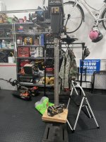
This past weekend I got some significant work accomplished. Before I get to it, here is an older pic of ½ of my workshop.

View media item 108517
OCD helps when putting things in order. Although, a few years ago I found out its not actually OCD, rather knolling. A concept I never knew was an actual thing… Anyway, here is a good video about shop rules and Rule #8 is “Always BE Knolling” (ABK), for those of us who find it irresistible to align things in the candy bins while waiting in line at the grocery store, feel vindicated…
I digress, so up to this point I disassembled the press.
Here is a pic of the chuck parts once I started cleaning them.

View media item 108518
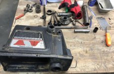
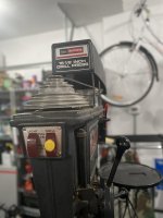
And some random pics of disassembled parts.

View media item 108523
View media item 108503
View media item 108508
View media item 108509
View media item 108524
View media item 108533
Since the owner’s manual does not have a copyright date or any date and the date code on the press and motor are completely a mystery to me, I went to the internet to see if I could date this press. I found a web site that has old Sears catalogs from the 1940s through 2009 that you can sort through, here is a link if anyone needs it.

https://christmas.musetechnical.com/

Anywho, starting with 1968 (my birth year) and working forward, in 1971 I found a press that either is the same press I have or very similar. The description is spot on, but the listed model number is not. The picture looks like my press, but I am not sure if it is the same model of mine or if my press was a year or two later. By the way it sold for $209.00 back in 1971 and that equates to $1,349.44 in 2020 dollars.

Edit 9-19-2021 This drill press is dated May of 1981 making this drill press an Emerson Gen 4 model.

Here is a pic of the catalog page.

View media item 108535
Once everything was disassembled I started to clean everything. First a bath in Simple Green for a few hours. Here is the Spindle in the Simple Green bath.

View media item 108513
And then anything with rust got an overnight bath in Evapo-Rust. This stuff is awesome.

View media item 108526
Parts in various stages of cleaning.

View media item 108539
View media item 108529
After cleaning to bare metal everything got a coat of WD 40 until I could decide what needed buffing and what lubrication I would use for re-assembly.
For the Chuck reassembly, I buffed everything then degreased, then used Mystik JT-6 EP Lithium Grease High Temp with 3% moly. Here is the chuck reassembled.

View media item 108537
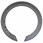
And here is the pesky C-clamp retaining ring (yellow arrow). You can see that there is very little room to work with. Getting is out was way easier than putting it back in.

View media item 108507
Next, I tackled the spindle pully insert. This is how it looked once I got it out of the press.

View media item 108528
New bearings and cleaned up and here is how it looks now.

View media item 108540
Next, I worked on the motor. This motor is a 113.12791 Craftsman 1/2HP Capacitor Start AC Motor with sleeve bearings. My knowledge about motors is very limited and I knew nothing about sleeve bearings when I started this.

View media item 108522
View media item 108514
View media item 108527
View media item 108538
It was fairly nasty inside but with careful cleaning, It look near new now.

View media item 108536
I masked off the motor and painted it with Krylon Industrial Tough Coat Rust Preventative Spray Paint in Gloss Machinery Blue/Gray. From everything I have read, this is a very close color match to the Craftsman gray and from what I can now see, yes, it is very close, albeit, a little glossier than the craftsman paint.

View media item 108532
The motor ran well before I started this, so I am hoping I reassembly it correctly and it continues to run. The sleeved bearings through me for a loop once I got it open. I was expecting to find sealed bearing like inside the press, that I could simply replace. Oh well, it was a learning experience. I have reassembled the motor, but I have not tested it yet. I wanted to get some feedback from you guys before I put any power through it.

View media item 108530
I lubed the wool in the sleeved bearings with 30wt Mobil motor oil. One thread I read, and the owner’s manual recommends “a good grade of medium weight mineral oil, such as automobile engine oil, SAE 20”. The one issue I do have and need help on is the order and orientation of the shaft spacers and seals. In this pic is the shaft assembly and under it are the parts in question. Since the owner’s manual does not have a parts diagram of the inside of the motor and it states that the motor should be taken to a motor repair shop, I am a bit lost. I completely forgot to take a picture of the spacers on the shaft before I removed them and now, I do not know the order and orientation. On the left side of the shaft is the (1) spacer, fiber, or plastic or something other than metal?, (2) rubber seal, (3) metal seal cap thing?, (4) retaining ring. On the business end of the shaft is (A) rubber seal, (B) retaining ring, (C) metal seal cap thing?, (D) another rubber seal, (E) spacer, fiber, or plastic or something other than metal?

View media item 108531
The metal seal cap thing has a protrusion that prevent anything butting up to the cap except the retaining ring and the protrusion sits over the top of the retaining ring. This is the only way I can see that this goes together. So, the order and orientation I used for the (as pictured above) left side (inner) of the shaft is like this diagram I made.

View media item 108541
The yellow is the (1) spacer, fiber, or plastic or something other than metal?, the green is the (2) rubber seal, the white is the (3) metal seal cap thing?, and the black is the (4) retaining ring. Does this look correct to yall?

The other end of the shaft I ordered and orientated everything like this.

View media item 108542
The black is the (B) retaining ring, the white is the (C) metal seal cap thing?, the green is the (A) rubber seal, the red is (D) another rubber seal, and the yellow is the (E) spacer, fiber, or plastic or something other than metal? Does this look correct to yall?

As I am inexperienced with electric motors, I am hesitant to power this thing up till I get some sort of guidance from yall.

The other thing I am hoping to get some help on is a source for a replacement rubber seal. This one (bottom of picture) is listed as craftsman 27813 Quill Gasket. I assume I can size it and find a supplier but if anyone has a good lead, I would appreciate it. For that matter, I should also look for replacement rubber gaskets for the motor shaft. Also, there is a fiber washer part # 38452 that goes with the hub assembly for the Quill return that I would also like to replace. The Quill Spring #38989 is still good, but I would like a replacement for it if it later breaks or gets too week.

View media item 108520
Ok, I still need to remove all the rust and clean up the large parts, Head, Table, Base, and Column. Since all the parts are large, a bath in the Evapo-Rust is not feasible so I think it’s the wire wheel and scotch-brite wheel for these parts.

View media item 108505
View media item 108515
View media item 108519
View media item 108525
View media item 108516
View media item 108534
That is where I am at the moment. I look forward to your comments, suggestions, recommendation, etc…
 
Last edited:
OP
1

11b30b4

Well-known member
Joined
Jul 16, 2020
Messages
1,028
Location
GA
Well, I decided to get back on the internet and see what I could find. When I first began this process, I found the Owner’s Manuel for the motor on the Drill Press. I did not know that there would have been a separate manual since I consider the drill press to be one product but I also know that in the Sears Catalog ad from a previous post you can see that one could order this drill press with a motor. Considering that, I suppose it makes since that the motor does have its own manual. In any rate, the Craftsman ½ H.P. Capacitor Start A.C. Motor Model 113.12791 owner’s manual I found on Vintagemachinery.org (Amazing site and wealth of knowledge) does not have a parts diagram. Actually, it does but only of the exterior of the motor and nothing for the interior.

View media item 108553
This diagram was somewhat helpful but what I needed was to see the parts aligned on the shaft. After 2 hours of searching on the internet and watching motor disassembly and rebuild videos, and I was nowhere closer to knowing how the various bits get ordered and aligned on the shaft. Then I found an exploded view of a different Craftsman motor (113.12170) and it dawned on me to check the Craftsman parts web sites such as Searspartsdirect.com, repairclinic.com, and ereplacmentparts.com and sure enough there was an interior parts diagram for the motor. This would suggest that there is a different publication available somewhere that has this parts diagram in it. For some time, I have been wondering if Sears ever published repair manuals (for use by repair technicians) so that they could repair all their products at service centers. If anyone know of these publications, I would greatly appreciate any information on them.
Anyway, now that I had an interior view of the motor and a list of most of the parts I built this graphic.

View media item 108552
And now I could make sure I put the motor back together correctly. I am missing the two #7 (30767) Power Tool Washers but they were not present when I disassembled the motor, so I assume that their absence does not greatly affect the motor. If I knew the size and thickness of them I could better source them but without any additional information I cannot replace them. I will replace the rubber washers once I find a good substitute. Regardless, I reassembled the motor and powered it up and presto, works like a charm.

View media item 108543
View media item 108544
So, I only need to reattach the data plates and the motor will be done for the time being.

Next, I Continued to clean up other parts. I had originally cold blued all the black parts but since cold bluing does not prevent rust I decided to go back and strip these parts and then coat them with KG Metal Coatings 2400 series Gun-Kote. I have been using this coating on firearms for years and love it. This bake on protective coating has a particle size of less than 10 Microns so it should not interfere with the operation of these parts. The only real issue I have experienced is that one set of the barrel locks is continuing to bleed oil when heated so I am having to heat degrease, heat degrease, heat degrease… to get these two parts clean before applying the Gun-Kote.

View media item 108548
View media item 108551
View media item 108549
Here is the reassembled Spindle Assembly. I still need to buff and clean the Quill Tube.

View media item 108546
Here is another pic of the cleaned and assembled spindle pully insert.

View media item 108547
Next, I sprayed several of the parts with the Krylon Industrial Tough Coat Rust Preventative Spray Paint in Gloss Machinery Blue/Gray.

View media item 108550
Lastly, I started to clean up the larger parts. For the Column I hit it with a scotch-brite disc on the angle grinder then cleaned it with acetone then slapped a layer of Metal Rescue Gel on it and wrapped it in plastic.

View media item 108545
My Caswell Plug N’ Plate kit came in yesterday so I will be plating the hub rods soon. Once I get a feel for the plating, I may plate the Depth Stop Rod as well but I need to see how the plating goes before I decide to do that.

Also, I grabbed a can of Blaze Orange Tool Dip and a Mix your own color Tool Dip. I will be dipping the Lock Handles to replace the rubber grips. The original grips were an orange but not a blaze orange so mixing my own color will be my first attempt and if that fails then the blaze orange is the fall back plan.

And that is where I am at, at this point. Thanks for the interest.
 
Last edited:
OP
1

11b30b4

Well-known member
Joined
Jul 16, 2020
Messages
1,028
Location
GA
Last night I removed the plastic and cleaned off the column. Next I used an orbital sander and 220 grit then 320 grit to finish off the column. Overall, I am very happy with how it turned out. I will apply a layer of lubricant or way before reassembly but for now, it’s good to go.

View media item 108556
View media item 108558
View media item 108560
Next, I started buffing the lock handles.

View media item 108557
After I finished the lock handles, I moved on to buffing the quill tube and then the hub assembly.

View media item 108559
View media item 108555
View media item 108554
So getting close to reassembly, thanks for the interest.
 
Last edited:

JZiggy

Well-known member
Joined
Dec 1, 2014
Messages
990
Location
Atlanta
Wow, that is one thorough overhaul. Nice work!

This board focuses so much on the 1950's Craftsman drill presses (One is my daily user and have had a dozen pass through my shop) we don't see a ton of the mid 70's ones. But this style of drill press is great and a super practical design.

I recovered one out a shop deep in the Santa Cruz mountains back when I lived in the Bay Area. I brought it home with me and my dad uses it in his shop.

7B0AHNa.jpg

hyULUpS.jpg

MGCPSbR.jpg


It's cool that it is the "commercial" version which seems to be refer to the slit in the front of the head casting and the adjusting bolts. I've never quite figured out the procedure required to get that adjustment just right.

I'll be following your rebuild for ideas for when/if we end up stripping this one down. For now it's just been wiped off, adjusted, and put to work.
 
OP
1

11b30b4

Well-known member
Joined
Jul 16, 2020
Messages
1,028
Location
GA
JZiggy, thank you. Yes, I think the commercial variant has the backlash adjustment. I also do not know how to properly adjust this but perhaps someone here knows how to adjust it.

Ok, last night I finally got all the oil gassed out of the one remaining set of barrel locks and got them coated with the KG Gun-Kote.

I picked up a few additional gallons of the Evapo-Rust and have the head sitting in the solution. I am hoping to clean up and paint the head, table and floor plate this weekend. Perhaps even reassemble the press on Sunday but I will need to see how things go.

I played with the plating kit. In these pictures the hub assembly rod on the left is the plated on. Its hard to see a real difference but I am hoping it will be more resistant to tarnish and rust.

View media item 108564
View media item 108565
After I got the hang of how this kit works, I did all the hub assembly rods and the lock handles. I don’t think I will do the depth gauge rod because plating the threads with this wand it is near impossible.

View media item 108567
View media item 108566
Lastly, this label from the motor was fairly worn so I made a new one. I will be cleaning up all the labels and data plates over the weekend as well.

View media item 108563
View media item 108562
That’s it for the update. Thanks for the interest.
 
Last edited:

FrankLee

Well-known member
Joined
Sep 13, 2010
Messages
3,551
Location
seMI, 48317
I'm late to the party, but better late than never.

I believe your drill press first appeared in the '73/'74 catalog. The model number closely matches the catalog number 2137N2. Other give-aways are the orange plastic lock handles and the multi-level table. Earlier lock handles were the taper style and earlier tables were a single plane.

There are many differences when compared to the earlier '40s to '60s models, but there are also many similarities. Several parts are downward compatible.

Very nice attention to detail!


How did you remove the large info panels on the sides?
 
OP
1

11b30b4

Well-known member
Joined
Jul 16, 2020
Messages
1,028
Location
GA
FrankLee, thank you for the information. In reference to your question on how I removed the data panels on the sides. Each panel was held in place with 4 ¼” long #4 Screw Nails. Honestly, I have seen these things before but never knew what they were called. Even the fire gods at handy ace did not know what to call them; however, after searching the internet for a bit I located them on McMaster-Carr’s site.

View media item 108588
Anyway, the holes these things are hammered into go all the way through the wall of the head, so I just grabbed a 1/8” punch and punched them out from the inside. Yes a few of the were in very tight places and before I took the time to read your entire thread (and see the tool you made to remove them) on the Craftsman Rebuild, I used a 2.5mm Allen head bit held in vice grips and then struck the back side of the bit with an extension rod. Not ideal but it got the job done. Obviously, hammering the new screw nails in after the paint and cleanup was much easier.

Two of the other badges for my press were held in place with adhesive. I cleaned off the back side of the badges and applied 3M outdoor double-sided tape and stuck them back in place after the paint and cleanup. Further, the one data plate on the motor was applied with an adhesive back and I was able to preserve the adhesive when I removed it. Re-application was simple and straight forward. Actually, the only badges that gave me a hard time were the white directional label from the motor which I remade, and the on/off data plate. Almost all the data plates had a thing clear plastic layer on then and I thought it was the typical clear plastic that is normally removed by the user once you set up your equipment. Well it may have been a clear plastic cover back in 1970 whenever but when I tried to remove it from the on/ off data plate it pulled the lettering with it. So, I left the clear plastic in place on all the other badges. For the on/ off data plate I made a stencil, sprayed the new letter on with flat black rust-Oleum and presto.

Update, I have finished… Well mostly, I will need to do some work on the pully cover later on but for now the press is done.

First, I removed all the rust from the head, table, and floor. Yes, I ended up going and grabbing 4 more Evapo-rust gallons and then submerging the parts for 12 hours each. This is way easier than cleaning them all up with an angle grinder and the Evapo-rust is reusable so its was a good investment.

View media item 108575
Once the rust was gone, all three parts were degreased and cleaned. Next I masked off any parts that did not need paint and shot them with the Krylon Industrial Tough Coat Rust Preventative Spray Paint in Gloss Machinery Blue/Gray.

View media item 108582
For anyone interested, here is the head and I have painted the top ½ (red circle) with the Krylon Industrial Tough Coat Rust Preventative Spray Paint in Gloss Machinery Blue/Gray, the bottom ½ (yellow circle) is the original Craftsman Gray paint. As you can see, the Krylon is glossier but otherwise it’s a very near color match. For spray paint that is incredible.

View media item 108587
Now that all the sanding was done, I went ahead and applied a layer of Johnson’s wax to the column and the table face. I have not used this stuff since I was buffing floors in the barracks back in Germany.

View media item 108579
I bolted down the floor and locked in the column.

View media item 108580
Next, I broke out the “create your color” Plasti-dip. I needed to cut off the plastic handles from the table and head locks to properly clean then up. Since the plastic handles are no longer available, I decided to use Plasti-dip to address this. The problem was the color, and with the “create your color” kit I could fix this.

View media item 108586
All of my grips are an orange-red color, so I was able to mix up the Plasti-dip to a fairly close match.

View media item 108577
Anyway, all the grips got dipped 4 times total. I am very pleased with the results.

View media item 108584
View media item 108572
I reattached all the data plates and badges then it was time to reassemble.

View media item 108578
I didn’t take any pictures of the assembly. This is the first time I have ever done this, and I was concentrating on the task, trying to recall how I disassembled everything, and how stuff logically went back together. I am fairly certain everything went back together correctly. The press runs very quiet and is like new.

View media item 108581
View media item 108573
View media item 108568
View media item 108576
With the press reassembled and running like new, there are two things I will fix later this year. First, “someone” cut a hole in the pully cover on the right side (facing the press). I assume this was because someone did not know that the motor (and by extension the drive pully) could be shifted left and right on the mounting plate and fix the rubbing on the inside of the cover. That idiot tends to leap before looking at times and later spends a lot of time fixing his blunders. The cover has a lot of scratches and gouges on it so a fiberglass and filler putty fix is in my future. Should be fairly simple to do once I have the time.
Second, the stop nut for the depth gauge is missing. I have no idea where to procure a replacement and my milling/ lathe skills are not good enough to make a replacement. If anyone has any ideas, I would love to hear them. Apparently, the thread is an Acme thread but that’s all I know at this time. Ultimately the stop nut is not a deal breaker since the thumb screw on the depth gauge pointer is sufficient to stop the travel of the quill.

Lastly, I cleaned up the table as best as I could. There are several pits in it from someone (not me this time) who drilled into the table in a few places. I see no way to fix these. I think the table is cast iron and spot welding the pits is not something I am equipped to do. So, I will just overlook them and drive on.

Well this have been a fun and very educational project. I hope the information here can help someone on their own rebuild. Now I will move on to my other drill press, a craftsman 8” 3 speed 1/6 HP Benchtop Drill Press (113.213722).

View media item 108583
Thanks for the interest.
 
Last edited:

FrankLee

Well-known member
Joined
Sep 13, 2010
Messages
3,551
Location
seMI, 48317
Very nice work!

There are several different names for those fasteners; Craftsman calls them "panel screws", McMaster calls them "drive nails", others call them "drive screws". Regardless of the name, they're all a pita. Most of the time I drill, tap and replace them with machine screws. It's so much easier. I've got dozens of used panel screws in a jar on the shelf.
 
OP
1

11b30b4

Well-known member
Joined
Jul 16, 2020
Messages
1,028
Location
GA
Thank you Frank. Now i need to start the teardown on the 8" press.
 

lafester

Well-known member
Joined
Mar 1, 2017
Messages
2,191
Location
Northern CO
That has to be the most complete rebuild of that model ever done.
Now you just need the secondary tilt table to be complete.

Looks great!
 
OP
1

11b30b4

Well-known member
Joined
Jul 16, 2020
Messages
1,028
Location
GA
Lafester, thank you. Those tilt tables are damn hard to find.
Provincial, thank you.
 
OP
1

11b30b4

Well-known member
Joined
Jul 16, 2020
Messages
1,028
Location
GA
Just a quick update and a question for whomever could provide a recommendation.

I rebuilt the Jacobs Chuck and shortly after finishing my rebuild I performed a runout check. I was getting .007 and figured I will re address it later.

So, this week I check the runout again. Spindle fully lowered and lock in place. Here are the results.

View media item 108589
Spindle assembly (Red Arrow) = .001
Chuck sleeve (Yellow Arrow) =.008
Chuck body (Blue Arrow) = .007
Turned aluminum rod in chuck (not pictured) = .007

So, I removed the chuck.
On the taper with chuck removed (not pictured) = .001
I put the chuck back on got the same results.
Chuck sleeve (Yellow Arrow) =.008
Chuck body (Blue Arrow) = .007
Turned aluminum rod in chuck (not pictured) = .007

Since I rebuilt this chuck, I thought it could be the chuck so I ordered an exact replacement (Jacobs Chuck 14451 Heavy Duty Plain Bearing Taper Mounted Chuck, 0.5" Maximum Capacity, 2" Sleeve Diameter, 3-45/64" Close Length in case anyone was looking for one with the locking collar) from Amazon ($98.26) after speaking with tech support at Jacobs.

I cleaned the taper with wet sand paper 800-2000 and wiped everything down then attached the new chuck and I am still getting.
Chuck sleeve (Yellow Arrow) =.008
Chuck body (Blue Arrow) = .007
Turned aluminum rod in chuck (not pictured) = .007

If anyone has any idea what is causing the .007 runout please let me know.

Also, if anyone has a Jacobs chuck with the locking collar and has been looking for a good removal tool. Gearwrench (is owned by Apex tools as is Jacobs Chuck) makes an adjustable pin spanner wrench that works perfectly. GEARWRENCH 3/4" to 2" Adjustable Pin Black Oxide Spanner Wrench 3/16" Pin - 81861, Multi ($29.99 on Amazon).

View media item 108591
View media item 108590
View media item 108592
Well that is all I have for now. Thanks for the interest.
 
Last edited:

MiniVanMan

New member
Joined
Nov 27, 2020
Messages
2
Location
Central Illinois
I just scored one of these on a facebook find for $150 - its in immaculate condition ESPECIALLY considering the manufacture date is December 1st, 1982 making it 3 years older than me lol. I took it part just short of pulling the bearings and cleaned out the old grease and greased it up with TW25B. I got the chuck apart and going to clean it in an ultra sonic cleaner tomorrow and get some TW25B on it as well. I ordered a Jacobs 34-33C that i plan on using and keeping the original put away, I'll abuse the chinese chuck and save the made in usa. I need to check the runout on it but the thing is so clean I can't imagine it being out of tolerance.
 

Attachments

  • IMG_4721.jpg
    IMG_4721.jpg
    68.5 KB · Views: 42
  • IMG_4720.jpg
    IMG_4720.jpg
    59.7 KB · Views: 41
  • IMG_4717.jpg
    IMG_4717.jpg
    159.6 KB · Views: 41
  • IMG_4718.jpg
    IMG_4718.jpg
    161.2 KB · Views: 42
  • IMG_4716.jpg
    IMG_4716.jpg
    131.9 KB · Views: 48
  • IMG_4648.jpg
    IMG_4648.jpg
    155.3 KB · Views: 48
  • IMG_4719.jpg
    IMG_4719.jpg
    146.5 KB · Views: 53
OP
1

11b30b4

Well-known member
Joined
Jul 16, 2020
Messages
1,028
Location
GA
MiniVanMan, that's a good find. I see these presses going for 200 ish and are rusted badly so 150 for a clean machine is a score. I agree with your thinking on the china chuck. I am interested in what your runout will be. Happy drilling.
 

MiniVanMan

New member
Joined
Nov 27, 2020
Messages
2
Location
Central Illinois
Part number question for the bearings on the spindle. Is the top the same as bottom? see attachment for the part in question. thanks

MiniVanMan, that's a good find. I see these presses going for 200 ish and are rusted badly so 150 for a clean machine is a score. I agree with your thinking on the china chuck. I am interested in what your runout will be. Happy drilling.
 

Attachments

  • Part#.jpg
    Part#.jpg
    107.2 KB · Views: 51
Last edited:
To avoid these ads, REGISTER NOW!
OP
1

11b30b4

Well-known member
Joined
Jul 16, 2020
Messages
1,028
Location
GA
MiniVanMan, yep both are the same as is the case with the spindle bearings, they are different from the quill bearings but both spindle bearings are the same bearings. So if you are planning on replacing all the bearings you will need two Craftsman Part # 3509 bearings for the quill and two Craftsman Part # STD 315253 bearings for the spindle pulley assembly. The belt is Craftsman Part # 71138 but I do not recall the specifications on it. If you use freemont industrial you can search by the craftsman part number or the drill press model number. Otherwise take measurements and you can order from accurate bearing co.
 
OP
1

11b30b4

Well-known member
Joined
Jul 16, 2020
Messages
1,028
Location
GA
Mikeinri, you are welcome. I have 4 drill presses now and I still use this drill press as my primary work horse. Its not as nice to look at as my 100 and 150 series but it is the most capable and Emerson used almost the exact same method of two bearings in a spindle assemble with machined bores into a cast head. I see no reason one could get the same quality (run out) on this drill press as you could a 100 or 150. As an added advantage you get a light and more sheve options on each pulley. I will most likely never part with this press.

Besides, it was my first rebuild and was the reason I found GJ so there is that as well.
 

mikeinri

Well-known member
Joined
Nov 29, 2019
Messages
8,206
Location
MA
Is it possible to add a lift table feature to this DP (if they can be located)?

Mike
 
OP
1

11b30b4

Well-known member
Joined
Jul 16, 2020
Messages
1,028
Location
GA
Mikeinri, I believe craftsman made a lift table accessory and I believe there were a few other brands that would work as well. I also believe some people have used lift tables from other brands of DPs on craftsman DPs. The best source for information on the Craftsman DPs is Frank Lee. He know almost everything ther is to know about all craftsman DPs from the very beginning, through the Atlas, King Seeley, Dunlop, and Emerson lines.

Checkout page 1 and scroll down to the Craftsman Drill Press Options and Accessories:

https://www.garagejournal.com/forum/showthread.php?t=227480
 

mikeinri

Well-known member
Joined
Nov 29, 2019
Messages
8,206
Location
MA
Interesting. There's one near me, looks identical to yours. Nowhere near as good a price as yours, of course...

Mike
 
OP
1

11b30b4

Well-known member
Joined
Jul 16, 2020
Messages
1,028
Location
GA
Mikeinri, I see them pop up all the time and they go from free to 200 bucks. There were actually 4 generations of Emerson DPs I believe (Frank Lee or Lafester would know). Anyway, the later in the generations the more they diverged from the King Seeley design and honestly the cheaper the product became. For a press like the one I have, I would not recommend paying more than 100 bucks. If you are not in a hurry one will pop up eventually for 50 or 75. Be sure to just look daily at FB marketplace, Craig's List, and Offer Up. I got mine from Offer Up/ Let Go. I have seen the awesome 20" industrial model with 2HPP motor and production table twice now but both times they want 500- 750 for them. I believe my press is 1974ish and that is as new as I would be willing to purchase.
 

mikeinri

Well-known member
Joined
Nov 29, 2019
Messages
8,206
Location
MA
They're asking for close to $300 for this one. There was a newer one listed for $200 last week, it sold in a few days.

Mike
 
OP
1

11b30b4

Well-known member
Joined
Jul 16, 2020
Messages
1,028
Location
GA
Another thing I do is to sign up for estatesales.net, then do searches for sales in your area. Look at all the pictures and you may see a DP in the pics that is what you are looking for. I purchased three vises last weekend from estate sales doing this. None of these vises were listed anywhere for sale except in the estate sales. I have seen a ton of wood shop equipment for sale in this way. Most of the time its not what I am looking for but on occasion I will see something I am interested. The key is once you find something, make sure you get to the sale at least an hour before it starts since there are a ton of tool hunters who use this method.
 

Clnilsen

New member
Joined
Mar 2, 2018
Messages
1
Thanks for the write up! this thread insp me to find one of these, and I’m doing the same restore now.

One question for you - how did you remove the spindle pully insert (that has the bearings attached) out of the drill head body? I got the pulley off, but for the life of me I can’t get the pulley insert with the bearings free. Any wisdom is appreciated!
 
OP
1

11b30b4

Well-known member
Joined
Jul 16, 2020
Messages
1,028
Location
GA
Clnilsen, congratulations on acquiring an great DP. It has been so long since I did this rebuild, I do not actually remember. I think I used a 1.5” wooden dowl and tapped the bearings and spindle assembly from the bottom (through the quill hole) and used a rubber mallet to hit the dowl. One big suggestion I have for you is to read through FrankLee’s Craftsman Drill press thread. This machine is an evolution of the 100 and 150 series and has a lot in common. It may not be a big a help for the spindle pulley assembly but most of the parts are extremely similar.


Also, just plan on replacing those bearings so damaging them is not a major concern as long as you don’t damage the spindle assembly or the headstock. Once you have it out just replace all 4 bearings with new ones and that will greatly improve performance. I recommend American or Japanese made bearings. Stay away from the Chinese ones on amazon. Just put a micrometer on them and get basic measurements (bore, outside diam, thickness) Also I do not recall if the spindle quill bearings have a 5/8” bore or not but a lot of Craftsman stuff does so measure carefully. Let me know if you need anything further and have fun.
 

RC53

New member
Joined
Oct 31, 2017
Messages
3
I have the same drill press (113.213780) which I purchased new in 1981. It has been very reliable and gets a lot of use. The one thing I don't like about it is the amount of vibration. Small items that are loose on the table will vibrate, make noise and move around. There is not a whole lot of difference with the belt on or off so I always figured it was the motor. Does anyone else have this issue? Thanks
 

Hoorn

Well-known member
Joined
May 19, 2020
Messages
1,140
Location
Glendora, CA
Thanks for the write up! this thread insp me to find one of these, and I’m doing the same restore now.

One question for you - how did you remove the spindle pully insert (that has the bearings attached) out of the drill head body? I got the pulley off, but for the life of me I can’t get the pulley insert with the bearings free. Any wisdom is appreciated!
CL, I know I'm about a week late, but one of the most overlooked procedures is the removal of the head screws located on each side of the head frame. They're not really visible being so deep, so it's easy to forget about them. These secure the spindle bearings and they're not coming out unless you remove those screws.
 
Last edited:
OP
1

11b30b4

Well-known member
Joined
Jul 16, 2020
Messages
1,028
Location
GA
Horn and Clnilsen, I don't recall if there are screws in the headstock that lock the spindle in place like the 100 and 150 series. Looking at the owner's manual and parts diagram, possibly #74 (t32124) is holding the spindle bearings inside the headstock.

RC53, I have to say that I get vibration on all my drill presses and two of them are bolted to the concrete floor. Both my 150 and this drill press are bolted down but the table still has enough spring in it to lightly bounce when there is any type of vibration. It is more pronounced when I am working on something heavy on the table. Lastnight I used my 150 to drill two holes in the headstock of another 150 headstock and even though the headstock was clamped down, the table had enough spring in it to vibrate as the bit forced its way through the iron.

full
 

RC53

New member
Joined
Oct 31, 2017
Messages
3
11b30b4, Thanks for the reply. Maybe the vibration is normal and I'm expecting too much. I've lived with it all these years and it doesn't negatively impact results. I have a baltic birch auxiliary table mounted on the cast iron table and that tends to amplify the vibration. I have considered replacing the motor with a ball bearing Baldor L3504. But it costs as much as I originally paid for the drill press and may not run any smoother.

I have a 1940 craftsman bench top drill press (101.03622) and it has little to no vibration, perhaps due to the shorter column.

By the way thank you for posting your rebuild, it was very informative (and well done).
 
OP
1

11b30b4

Well-known member
Joined
Jul 16, 2020
Messages
1,028
Location
GA
Hoorn, no worries, I am constantly having to scroll up to see what machine we are talking about whenever I reply.

RC53, I suspect you are correct about the longer the column, the greater the vibration. My 100 series bench mount has no noticeable vibration but all my floor mounts do. I suppose if you truly want little to no vibration you would need to look for an industrial machining drill press like a Clausing; however, the price tag for a used one will be big and most of them are 220 volts. These craftsman drill presses are shop quality and were widely used due to availability and price compared to industrial grade presses.

As for your motor, If you run the motor on a bench, is there vibration? What type belts are you using? None of my motors produce significant vibration and I use cogged v-belts on all of my presses except this 113 press. Since this V-belt is so small, I do not believe they make a cogged version for it.

I am also wondering what your runout is like. Do you detect vibration in the chuck, perhaps your bearings are bad? I always install new bearings in anything I rebuild. Anyway, I hope some of this helps and I am glad you found the thread informative.
 

RC53

New member
Joined
Oct 31, 2017
Messages
3
11b30b4, Sorry for delay in responding, I got caught up in troubleshooting and wanted to narrow down a root cause. As it turns out the motor was indeed the source of the vibration. It is the original Craftsman 1/2 HP cap start with sleeve bearings (113.12791). I'm not sure that there is anything actually wrong with the motor, it's just not a smooth running motor. I ordered a Dayton (4VAG6) 1/2 HP cap start with resilient mounts and the drill press runs as smooth as silk now. There is virtually no vibration, and it passes the nickel test. I can't believe it took me 40 years to upgrade the motor.

To answer your questions: The motor does vibrate on the bench. It's a 113 drill press with the skinny little belt. The runout is .002 - .003 just below the chuck jaws measuring against a half inch drill blank. No vibration in the chuck. I will probably replace the quill bearings for good measure.

Thanks for your input, it helps to talk it through.
 
OP
1

11b30b4

Well-known member
Joined
Jul 16, 2020
Messages
1,028
Location
GA
RC53, glad you got it sorted out. I am not a fan of the sleeve bearing motors. The dayton should serve you well.
 
To avoid these ads, REGISTER NOW!
Top Bottom