To avoid these ads, REGISTER NOW!

11b30b4’s Craftsman 103.24260 Band Saw Rebuild

11b30b4

Well-known member
Joined
Jul 16, 2020
Messages
1,029
Location
GA
This weekend I purchased a Craftsman King Seeley Band Saw (103.24260) from Offer-up for $100.00. I had not expected to pay that much for it but I also came with a spindle sander and the motor for the sander was a craftsman motor, so I figured overall the 100 was worth it.

View media item 110087
View media item 110088
I have been looking for a Craftsman King Seeley band saw for some time. Ideally, I would like to acquire a 103.24280 model with a pedestal stand. The damn stands are very hard to find down here in GA.

I have not taken a good look over this machine yet, but I have noticed an interesting motor and pulley assembly. The band saw motor has two rpm setting from a switch on the stand. Then there are the numerous pulley stages on the motor pulley and there is a spindle assembly (middle pully) between the motor and the saw. All of this means a range of rpms to run the saw.

Once I get this thing in my basement, I can take a closer look and see exactly what I am dealing with. The sander and table all seem to be hand made from plywood and a metal frame. There is a handmade miter gauge and an added flexible light. Nothing looks factory but certainly period.

So, this will be an interesting rebuild. I will be taking it slowly on this one.

Thanks for the interest.
 
To avoid these ads, REGISTER NOW!

Cruzan80

Well-known member
Joined
Jul 22, 2015
Messages
4,304
Location
Denver, CO
Looking forward to it. I have one that is in the "for sale" pile that I picked up years ago. Ended up selling the fence on OWWM, but still have the bracket if you need it. Getting tension set is a bit trickier on these if you are going to be swapping blade thicknesses a lot.

Replaced with a power bronze 24280 on a pedestal. Only PB in the shop, but the OEM paint is in such good shape, I cant justify repainting.

Sent from my Phone 2 using The Garage Journal mobile app
 
OP
1

11b30b4

Well-known member
Joined
Jul 16, 2020
Messages
1,029
Location
GA
The elusive pedestal…. Well I guess I will find one eventually.

So I managed to get the band saw into the basement shop over the weekend and take a better look at it.

First the sander has the craftsman motor on it, still not sure what model and rpm.

View media item 110208
Next, here is a shot of the two-speed settings switch for the band saw motor.

View media item 110204
I still do not know what brand and type of motor this is other than it has a capacitor on it.

View media item 110203
Here are some pics of the pulley system for speed adjustments.

View media item 110207
View media item 110205
View media item 110206
I assume the original owner installed all of this to get the speed low enough to cut metal. I will measure the pulleys and do some calculations to see what the speed was capable of doing. I had planned on getting a worm gear for this saw but I may not need one.

A while back I looked into lower the speed to cut metal on one of my other band saws and the general consensus, I was finding was that you could not or should not do this with pulleys. The worm gear is the preferred method. Does that sound correct to you guys?

More to come, thanks for the interest.
 

JZiggy

Well-known member
Joined
Dec 1, 2014
Messages
990
Location
Atlanta
There's no technical reason you can't use step pulleys to gear down for metal cutting. From the looks of it whoever made this setup had the right idea. Starting with 1100rpm is a big plus and the drive pulley on the saw is huge. As long as the shaft of the bandsaw runs 60rpm or less you'll be plenty slow for even stainless steel. I made a calculator a while back and will share it with you if I find it.
 
OP
1

11b30b4

Well-known member
Joined
Jul 16, 2020
Messages
1,029
Location
GA
JZiggy, thanks for the information and I apologize it has taken me some time to respond to your post.

I had put this rebuild on the back burner because I have been searching for the pedestal stand. These things are extremely scarce here in Atlanta. I can find the band saws well enough, but the pedestal stand has been an exercise in patience; however, that all ended this past weekend.

There is a pedestal stand selling on ebay for $200.00 plus $100.00 for shipping and I am not willing to drop $300.00 for the stand; however selling in northern South Carolina posted an ad for a Craftsman Band Saw 103.24261 (basically the same band saw that I already have) with a pedestal stand for $75.00. I contacted the seller last week and learned that several other people were ahead of me to buy it. On Thursday the seller notified me that everyone flaked out and that if I still wanted it, I could buy it. So, 4.5 hours (one way) I drove to buy the band saw and pedestal. At $75.00 and 9 hours round trip, this seemed like a deal to me.

My Army buddy is in town from Colorado, so he went with me and I gave him the band saw since all I wanted was the pedestal stand and this gave us 9 hours of quality time together to catch up.

View media item 112074
Once disassembled, the stand was placed in a citric acid bath and I am hoping to pull it out tonight.

Since I now have the stand, I guess I need to get on this rebuild. The disassembly of the band saw…

View media item 112086
View media item 112084
View media item 112082
View media item 112081
View media item 112080
View media item 112079
View media item 112078
View media item 112077
View media item 112076
The previous owner of the band saw had disassembled the band saw at some point because many of the bolts used were longer than the originals and he used a lot of washers as spacers. Other than the wrong bolts, everything else looks correct. I need to order replacement tires, blade, and bearings and figure out a fence option. I did purchase the aluminum table mount for a Craftsman fence from a member here on GJ but I still need to fabricate or locate a fence.

The other reason I have been putting off this rebuild is that I already have a working band saw that I use for everything except metal. I am hoping to convert this band saw for metal cutting. This beings me to the motor issue.

As you can see in the previous images the previous owner used a dual phase motor that ran at 1140 rpms and a jack stand stepped pully assembly to get his speed down for metal cutting. If I were mounting this band saw on a similar stand, I would simply replicate this setup and roll with it, but I will be putting the band saw on the pedestal stand. There really is no good way to add a jack stand between the motor and the band saw on the pedestal and keep everything looking clean and original. I am hoping to get the speed down to cut 1144 steel in thicknesses around ¾”. I believe I need a SFPM around 140 and a 14/1 blade ½” wide.

As I understand it, the other three options I have to slow the saw down are:
1. Use a worm gear box to slow the speed down. I have read that something close to a 20:1 gearbox would work for me?
2. Use a geared motor to produce the slower speed but hp and torque are my concerns here and I do not know what I need to be looking for.
3. Use a variable speed motor that I can dial in the correct speed. While this may be a good option for a lot of people, its not for me since this band saw will be dedicated for cutting 1144 steel.

So, this band saw came on a stand where the previous owner also built a drum sander on ½ of the stand. He most likely used the plans from popular mechanics or some other publication because this thing was totally hand made using a Craftsman 1/3 hp split phase motor (113.19665) that he discarded the bracket mount and installed the motor vertically with longer stator bolts.

View media item 112085
View media item 112075
This motor runs and has a 1725 rpm. This is most likely the motor the previous owner had purchased with the band saw and is period correct. IT would have looked nice mounted on the pedestal stand but there is the issue of the missing cradle mount. I am sure I could find one that fits but the rubber bushings that sit between the mount and the motor (fit on each end of the motor) are also missing and I am not sure I could replicate them.

I contacted Frank Lee to see if he had a mount and he does have one but its designed to bolt to the stator so I need to disassemble this motor and see if there are mounting holes in the stator. If there are, I will simply need to modify the stator band to allow for access to the mounting holes. However, this is all academic if I still need to slow the speed down. So, the math tells me that a 1725 rpm motor with a 20:1 gearbox should get me down to 86.25 rpm. depending on the pulley size I am working with I should be able to get the speed to 140ish sfpm. How would I go about installing a 20:1 gearbox on the pedestal? I am back to the same issue I have with the jack stand; although, this may be the lowest cost option. I am confident I can get a 20:1 gearbox for around $150.00. My other concern is, will the 1/3 hp motor produce enough torque and power when slowed to this speed to cut the metal?

The next option, using a geared motor seems the cleanest option with the smallest footprint. One motor to be mounted and the output pulley should be good to go; however, what do I need to ensure the motor is strong enough and still slow enough? Additionally, there is the cost, these geared motors are not cheap and although I am not opposed to getting a used motor, I really need to have an ideal specification to look for before I can determine the viability of this option.

So, some assistance from fellow GJ members would be greatly appreciated.

Back to the rebuild, all the parts are now sitting in a simple green bath and some of the parts will soon be heading to a citric acid bath. The rebuild continues.

Thanks for the interest.
 

JZiggy

Well-known member
Joined
Dec 1, 2014
Messages
990
Location
Atlanta
Hey Jeff,

If you have a 20:1 gearbox in front of that little motor it will have unstoppable torque. Your blade will slip on the tires well before you slow it down (ask me how I know).

My 15:1 worm gearbox is a Grove Gear unit from eBay (side note, I have a quart of the ISO680 or somesuch lube it needs and you are welcome to some since they only use a couple ounces). The motor plugs right into it and then the output shaft is 90* to the motor. You just need a mounting plate for both units together.
 
OP
1

11b30b4

Well-known member
Joined
Jul 16, 2020
Messages
1,029
Location
GA
Jordan, thanks for the information can you message me the link to the worm gear you used? I am sure I can fab a mount and I will most likely take you up on the ISO680. We need to get together anyway so I can get the motor mount pivot pin back to you.

Update,
Apparently the previous owner cut some sort of plastic with the band saw and dust and residue must have been hot and melted into the rough finish of the outer case on the back side. I tried cleaning up the front and back covers but the residue remained and would not come off with a hand wire brush. It did not occur to me to try heat to remove the residue and I went to the wire wheel in the angle grinder. This also took off the finish from the cover so I ended up wire wheeling both covers. Also the previous owner drilled 3 small holes into the back cover to internally mount the wire he ran for the spot light. I took this opportunity to fill these holes with PC-7. Tonight I should be able to clean the covers up and prime them.

I forgot to take pics but will get some tonight.

Thanks for the interest.
 

JZiggy

Well-known member
Joined
Dec 1, 2014
Messages
990
Location
Atlanta
It was a Grove Gear Flexaline. I got it on eBay and the link is defunct. I think you can google the Flexaline catalog and see what part numbers might work for you.
 
OP
1

11b30b4

Well-known member
Joined
Jul 16, 2020
Messages
1,029
Location
GA
Jordan, I have found several models which I assume are similar to your worm. Looks like the Flexaline is now the 800 Ironman series. However, a search on ebay for 15:1 worm gear speed reducer produced several options.

I would have preferred an inline option, but they are more expensive. One really cool thing I found was the Zero-max variable speed controller; although, I have read a few posts that the Zero-max will not produce the torque that a worm gear will. Either way this is a very cool devise.

View media item 112123
So, I think this worm gear will work, it has the correct shaft size, hp, and rpm inputs and should drop 1725 rpm to 115 rpm. The pulley sizes should do the rest to produce the proper speeds for metal cutting. I also believe I could fabricate an interface bracket for connect it to the motor. I am interested in what yall think about this option.

View media item 112124
I also took the opportunity to inspect the 1/3 hp motor to see if the mount that Frank Lee has would work. Unfortunately, the stator does not have any screw holes for a stator mounted base. Overall, the motor seems in good condition.

View media item 112122
View media item 112120
This motor would have originally had a resilient ring cradle mount like this one.

View media item 112125
I have learned that the rubber end cap rings are standardized so finding ones to work with this motor would not be a big deal; however, I do have a cradle mount on a particular craftsman split phase motor that has given me a ton of problems. Since I will not be using that motor, the rubber end cap rings are a good fit on the 1/3 hp motor. Finding the resilient ring cradle mount is another issue. The length of this motor is 7 7/8”, I have been unable to locate an exact match, but I did find one that is 7 1/2” long and it was about $20.00 so I purchased it. I am hoping to bend the ends out a bit to allow it to fit this motor. More to come on this once I get the mount.

As promised here is a pic of the two covers after the wire wheel.

View media item 112119
Another small issue is that the simple green pulled the reference marks off the table angle indicator. Here is a pic of it before it was placed in the simple green.

View media item 112087
It is now just a blank metal crescent tag on this part. I will work on developing a graphic for this and have Mattblast produce the decal for me.

Lastly, here is a pic of the pedestal mount after the citric acid bath. I need to wire wheel the parts then prime and paint.

View media item 112118
That’s it for the update,
Thanks for the interest.
 

JZiggy

Well-known member
Joined
Dec 1, 2014
Messages
990
Location
Atlanta
Ooh, that Zero-Max is a cool thing. Bonus points if you use that for sure!

That little Morse gearbox is a lot like mine. I expect it would serve the purpose perfectly fine. And yes, you can dial in the final speed with your final drive pulleys but you'll want them to be large enough diameter to get good traction with the belt.
 

y'sguy

Well-known member
Joined
May 1, 2010
Messages
1,341
Location
Tulsa, Oklahoma
11b30b4
I'm Following along to see how you attach the VSR. Should be interesting. I think Ryan did an piece on GJ about electronic speed reduction for his bandsaw quite awhile back? I'm just watchin'n tho I know you'll figure it out. It's mostly above my pay grade.
 
OP
1

11b30b4

Well-known member
Joined
Jul 16, 2020
Messages
1,029
Location
GA
Jordan, Y’sguy, and JoCoSawdust, so back in 2020 when I decided I wanted to acquire a King Seeley Band Saw, I knew I wanted to convert it for cutting metal. I already have a very nice 14” Craftsman Band Saw that I use for wood and plastic. At the time I also had a 12” Delta Band Saw that I almost never used once I got the 14”.

Regardless, after I restored my first King Seeley Drill Press, I started to look at their other products of the time and the Band Saw (on a pedestal stand) really jumped out to me as keeping in the 50s/60s semi art deco design. I actually like the 103.24280 model better and its more suited to repaint in a glossy paint but the 24260 is what I was able to find at a fair price for rebuilding. As I previously said, the pedestal stand was the hard find. figuring out how to reduce the speed on a pedestal stand has been a bit of a challenge.

If I were mounting tis band saw on a standard box stand this would be a fairly easy decision but, on a pedestal, there are a lot more things to take into account.

Reducing speed on a band saw or a drill press is a fairly simple thing. There are a number of approaches that one can take but, on a pedestal, all the “guts” will be exposed, and I did not want to take away from the aesthetics.

After some research these are some of the methods I considered:

View media item 112212
Jackshaft
This band saw came with a Jackshaft or third pulley system. This uses three pulleys and two belts to drop the speed and there are a ton of pros going with this option. The obvious one is the cost, this system is extremely cheap to build. Additionally, if I use stepped pulleys, there is a wide range of speeds available to me. This exactly what the slow speed pulley system for drill presses that JZiggy sells is based on and Craftsman offered a similar system on the drill press. Further, adapting this to a mount that would sit on the column of the pedestal stand is not a huge struggle but its not the direction I decided to go with.

View media item 112208
Pull-Gear Speed Reducing Pulley
I found this system on one of Mr. Pete’s (Tubalcain) videos and it was a really cool idea. Pull-Gear sold three versions of this device that used a planetary geared drive to reduce the speed in a very compact design. The drive would have 2 or 3 sheaves on the drive to provide a range of speeds with a simple belt adjustment and could be activated with a flip of a lever. Mr. Pete’s model was the Model PG-7 which provided for a 7:1 reduction 6 spindle speeds from 45-3000 RPM. There are three major drawbacks from this system, otherwise it would have been perfect for my application. The first is the availability, Pull-Gear Co. made these in the late 50s and the company went out of business in the 60s so there are a very limited number of these things around. The second issue would be the cost, with scarcity, come an inflated price (just consider what gas is costing today), and the last major issue is the noise. On Mr. Pete’s video of this thing operating it is loud and would drive me nuts.

View media item 112213
Variable speed pulley
This is a similar idea to the Pull-Gear in that it is mounted directly to the shaft; however, instead of using gearing to reduce the speed, this design used one or two pulleys that have semi-conical walled sheaves that are spring compressed on the shaft. The sheaves can open or close essentially making the pulley larger or smaller in diameter. There are several companies that make these devises and the price can vary from 100-1000. The drawbacks of this system are that it really only provides a fairly small reduction since most of the variable speed pulleys only range from 1.5” to 7”. At best, with just two of these devises on my band saw (one open to 1.5” and one closed to 7”), I could only reduce a 1725 rpm motor to 1161 SFPM. Still too fast for what I want. Additionally, the tension verses the torque and the chance of a slipping belt also put me off on this idea. Regardless, it’s a cool mechanical approach to slowing speed in a belt driven system.

View media item 112210
View media item 112209
View media item 112211
Savage Mfg Band Saw Speed Converter
I learned of this device from bagged89s10 post here on GJ. Savage Mfg marketed this device under their label and for Craftsman as the “9-2342 Craftsman Slo-Speed Converter for 10-14" Band Saws”. This device reduces the speed with a 10:1 ratio and uses two gears with a two toothed drive belts in a case and it looks very “period correct” for my build; however, finding one is next to impossible and even if I did, I expect it would sell for 300 buck. Regardless this is the direction I would go if I could find and afford one of these drives. I should also note that Savage Mfg is also the developer or the Veri-Slo Speed Control for the 100 and 150 drill press that was marketed for craftsman and is also a really neat idea.

View media item 112229
ShopSmith Speed Reducer
This thing is very similar to the Savage Mfg design and could be adapted for use on my band saw. These things sell for 500 new but I can find them for as low as 50 bucks used. I really considered snagging one and adapting it to work with my pedestal design and I still may get one to play with at some point. Internally it looks like they copied the Savage Mfg design.

View media item 112123

Zero-max variable speed controller
There are actually a few manufactures that make similar products, but the Zero-Max looks to be stouter and more period correct of a design for something currently made. This thing uses two cams and odd shaped leavers that resembles the inside of a sewing machine rather than a gear box. This is most likely because the Zero-Max is commonly used on sewing machine motors. The output speed range for a 1725 rpm motor are 0-400 rpm; however, the output torque is only 12 in-lbs. So, for all its coolness, there are a few drawbacks. First, there are three basic types that produce output in clockwise, counterclockwise, and adjustable rotation. For my application, I need counterclockwise or adjustable rotation. Second, the internals look cool, but I am not sold on them standing up to the torque demands. If just one lever bends, then the entire thing is scrapped. Third, the availability of used ones is hit or miss and all the ones on ebay are CW rotation at this time. If a CCW pops up, I may snag it and play with it. Lastly, the cost of new drives is insane, like 300-1000 insane. The uses ones go for 100-200. Like I said, it’s a neat design and I really like the look but more than likely, a used ShopSmith Speed Reducer would be a better fit.

View media item 112237
Geared motor
Probably the most efficient method would be to go with a gearmotor. Essentially, this is a motor with a permanently attached gear box to reduce the RPMs. The largest hurdle to cross for this option is the price, I could by a new metal cutting band saw for what these things sell for. Nothing about this option looks period correct but it does have minimal footprint. The cost is just too high for consideration and most of these motors are 230 volts.

View media item 112230
Gearbox AKA Worm Gear
So, considering cost and a good bit of recommendations, I settled on a gear box. The gearbox I chose is a Falk Omnibox 15:1 reducer. At just over 100 with shipping this is a good option and provides me some options on how I mount it. Falk is reputable company with a good track record and this drive has dual output.

The current plan is to mount the motor low on the pedestal 90 degrees to the saw then the worm gear between the motor and the saw. We will see if I manage to fabricate this monstrosity and make it all look good…

The rebuild is coming along nicely. Following Frank Lees advise, I have waited until I disassembled everything to order parts.
Stuff I need to order or have ordered:
Tires
metal cutting blade
Cool Blocks
Thrust bearings
Upper wheel bearings
table insert
Additional U-bolt and mount for the worm gear
V-belts (size TBD)
Misc bolts as needed
Lamp parts
Wiring

I have degreased and de-rusted almost all the parts. Here are the pedestal parts after the citric acid bath.

View media item 112214
The column was badly pitted and was too long and wide for my lathe, so I decided to build a poor man’s lathe. I used two wooden furniture conical legs from home Depot, some 5/16” all thread, nuts and washers and 4 PU rubber casters also from HD.

View media item 112215
After some work the column came out very nice.

View media item 112216
The motor mount I ordered came in and fit perfectly for the 1/3hp motor so either I measured incorrectly or correctly, depending on how you look at it.

View media item 112218
View media item 112217
With that solved, I disassembled the motor and cleaned it up for painting. One of the things I did was remove the data plate. This comes up from time to time so I thought I would show how I do this. For most panel screws (the rivet looking things that hold a lot of the data plates on) you can simply knock them out from the back side with a small punch. However, on occasion you will come across panel screws that a blind (the hole is not drilled all the way through) or the back side is too cramped to access. For these I sue a Dremel cut off wheel and turn the head into a slot head. Then you can unscrew them out since the sides of the panel screw have a spiral thread to them.

Here you see the panel screw

View media item 112219
Here I have cut the slot in the head, just be careful not to damage the data plate if you hope to reuse it.

View media item 112220
And here is the removed panel screw

View media item 112221
If you want replacement panel screws, McMaster Carr is where I get mine.

After cleaning and masking, the motor was primed then painted. The stator got the Hammered Gold and the end caps got a glossy brown from Ace. Additionally, I primed and painted a lot of the other parts, some Gold some Brown.

View media item 112227
View media item 112226
View media item 112225
View media item 112224
View media item 112223
Here is a good pic of the brown comparison. One the left is the original brown and on the right it the Ace brown.

View media item 112222
I would have preferred to find a hammered brown in this shade, but the hammered paints are fairly limited in color choice.

I did clean up the face of the table but its was masked for painting before I thought to take a pic.

And that is where I am at.
We will see if I am able to pull all this together and it look good in the end.
Thanks for the interest.
 
Last edited:

JZiggy

Well-known member
Joined
Dec 1, 2014
Messages
990
Location
Atlanta
I ran across one of the newer Craftsman slo-speed converters. It was pretty rinky dink.

Lots of options to gear down for sure!
 

JoCoSawdust

Well-known member
Joined
Nov 19, 2018
Messages
2,416
Location
Eastern NC
Agreed on the "Pull-Gear" speed reducer. I posted one on Frank's DP thread that came on a DP I recently acquired. After removing it from the barnacle encrusted machine and doing some research on it, I tested it on the bench. It works and actually really slows the rotations down but as you mentioned 11B, that thing is noisy as hell. I'm not sure of what torque one of those would produce, much less than a than other options I suspect but the noise alone would scratch one of those off my list.
 
OP
1

11b30b4

Well-known member
Joined
Jul 16, 2020
Messages
1,029
Location
GA
JZiggy, did you buy the Craftsman Slo-Speed Converter? Do you still have it? Do you recall what it was selling for? I would really like evaluate it. The case looks to be sheet metal so I expect it would not be as “solid” as a worm gear but I really like the concept and the look.

JoCoSawdust, yep, Mr. Pete’s sounded like someone was dragging a shopping cart behind a car, through a parking lot, on its side. However, it is very compact, eliminates an additional mount, and has major cool points in my book. I just could not deal with the noise. Do you still have it? Are you planning on selling it and if so, what would you ask for it? If you do sell it, at least document an evaluation of it with lots of pics and post it here on GJ.

Update,

So the U-bolt that secures the motor mount to the column looks to be hand forged and had an excessive amount of rust and pitting. I cleaned it up but then decided to try to shine it up. Wire wheel, hand sanding, and a buffer wheel later it looks good enough for my project.

View media item 112249
I have been searching for a replacement U-bolt and/ or a second U-bolt since I will need an additional one for the worm gear mount. The trick is finding one that is similar to this one. It is not your normal U-bolt. The bend that wraps the column is flat which I assume helps to keep it from slipping on the column as well as assist in keeping the motor mount perpendicular to the column. Here are the measurements of the original

View media item 112238
I have yet to find a similar U-bolt so if anyone has a lead on one, please let me know. I can find round U-bolts all day long and I can even find flat U-bolts but not in the column circumference and length I need and most of those flat U-bolts are larger in diameter than ¼” I an sure I go as large as 3/8” or even 5/16” but that would be the largest I thing I do without drilling out the holes in the motor mount larger.

I also started to reassemble the motor but when I removed the masking and paper towel I stuffed in the arbor bore I realized that my cold water washdown I did to clean the end caps up has left a lot of water in the wool filling inside the cap bearings. I may need to place these end caps in some rice to draw out the water. I cannot assemble the motor until I get all the moister out of the wool then add the 30 wt motor oil back into the wool end cap bearings.

View media item 112250
And here are the aluminum cast parts that had a gray paint on them before the bath in simple green. I am still considering if I want to paint them or polish them.

View media item 112248
This evening I am hoping to mask and finish painting the pedestal and outer covers. The humidity here in GA is starting to become an issue for painting so I needed to let the parts sit a few days before masking.

Lastly, This is a sketch I mocked up to visualize the pulley system. If all goes well, this is a good approximation of what I should have once I finish this project.

View media item 112252

And that is it for now.

Thanks for the interest.
 
Last edited:

JZiggy

Well-known member
Joined
Dec 1, 2014
Messages
990
Location
Atlanta
The slo-speed converter was not like one with the rounded housing. But it was made with little rubber timing belts. I can't find a picture right now, sorry...

All that being said I think the worm gear is a way more robust solution.
 
OP
1

11b30b4

Well-known member
Joined
Jul 16, 2020
Messages
1,029
Location
GA
JZiggy, thanks for the update, I agree the worm gear is rock solid.


Update,

Well earlier this week I masked and painted the brown on the base of the pedestal stand.


full


And here is the pedestal stand assembled.


full


Next, I started masking the covers. In this pic you can sort of see the 1/16” masking tape between each raised panel line. Yep that was a lot of fun working that thin masking tape and trying to keep it in a straight line. Anyway, I ran out of the thin tape and ordered some off Amazon that will not arrive until Saturday. Hopefully I will be able to paint on Sunday or Monday.


full


Lastly, the replacement tires and worm gear arrived. I will hold off on installing the tires until I start re-assembly. I still need to fabricate the worm gear mount and figure out all the alignment issues.


That’s it for the update.


Thanks for the interest.
 
Last edited:
OP
1

11b30b4

Well-known member
Joined
Jul 16, 2020
Messages
1,029
Location
GA
Update,


The 1/8” masking tape arrived, and I realized I meant to order 1/16”. Oh well, TBH thew 1/8” looks better and makes the lines “pop” more.

Obviously, I finished masking the covers then sprayed on the brown and quickly removed the masking tape. I am very pleased at how these turned out.


full


Once the covers were dry, I mounted the feet on the back cover then mounted the cover to the pedestal.


full


full


I started reassembly and realized I should have taken some pics of the inside of the saw with everything inside and assembled. I did take pics of the parts groups as I disassembled then but the orientation of a few parts has me scratching my head and the parts diagram is not a big help.


full


The motor is assembled and test and all is well. I received the stator band decal from Mattblast but I am holding off on mounting it until I see how the motor will be orientated.


full


I cleaned up the Craftsman logo. On my friend DAC’s 103.24261 saw his lettering on this badge is red but, on my saw, it was chrome like. I considered painting it red, but I feel keeping with the chrome will look better with my paint scheme.


full


I have run into a snag,

Somehow, the holes in the upper wheel support bracket have magically expanded and the splined end of the guide rods just drop out of the bracket rather than fit tightly into the bracket.


The rods are so loose that using thread lock will not be enough to keep them in place. As I see it, there is really only two options. One is to reduce the hole size in the bracket. The other is to increase the circumference of the splined ends of the guide rods.


While the rods would be the parts that would be the easiest to reproduce should I mess one or both of the up while trying to add weld to them. The bracket is where I believe I will have the best affect.


The plan is to braze the inside of the holes in the bracket with Alumiweld. This will be stronger than the surrounding aluminum and can be drilled out for a tighter tolerance to the guide rod diameter allowing for the splines to make new indentations.


Also, I will be talking this week with someone I know who can possibly replicate the motor mount for the pedestal. I need a second one to mount the worm gear on.


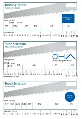
I was asked so here is a list of the various parts I have ordered for this project. NOTE: there are a few things to be aware of if you have a different model 103 band saw. First, Olson now makes the round cool block for these saws so you no longer need to turn down a set of rectangles to make rods. Be sure measure the blade guides you have on your saw, there are two sizes of rods, 5/16” are Olson part CB50020BL and ¼” are Olson part CB50040BL. Next, make sure you get the correct tooth number for your blade depending on what type and thickness of metal you will be cutting. Next, there are two different sizes of table inserts for the 103 series. I have not ordered a replacement yet so I do not have a link for my part yet but they are widely available on ebay. Lastly, the upper wheel bearings are a 5/8” bore double shielded 6202 bearing and you need two of them. The size is 5/8"x35x11mm. The standard 6202 is all metric so make sure you get the special 5/8” bore.

Tires


Metal Cutting Blade (10/14 tooth)


Cool Blocks (5/16”)


Thrust Bearings


Upper Wheel Bearings (NTN 5/8” bore)


Table Insert

TBD

Additional U-bolt and mount for the worm gear

TBD

V-belts

(size TBD)

Misc bolts as needed

TBD

1/8” Masking Tape


Electrical

Toggle Switch Cover


Motor Power Cord


Lamp Parts:

Goose Neck


Hex Nuts


Push Through Socket


Washer


Lock Washer


Metal Lamp Shade


And that is where I currently am in this project.

Thanks for the interest.
 
To avoid these ads, REGISTER NOW!
OP
1

11b30b4

Well-known member
Joined
Jul 16, 2020
Messages
1,029
Location
GA
FrankLee, JoCoSawdust, Jayman17, thank you all for the kind words.


Update,

Yesterday I dropped by the guy I know who has a plasma cutter and asked him to duplicate pedestal column motor mount. 2 hours later I have two motor mounts, and this one got the primer and paint last night.


I played around with the Alumiweld and discovered that the upper wheel support bracket is either some other type of alloy or the Aluminum is a different type. I know this because the MAP gas torch melted the aluminum. Luckily, I was able to prevent any significant damage from happening. I filled in the bore hole on one side of the bracket and then redrilled it for the guide rod. The alignment of the newly drilled hole turns out to be the most difficult part of this process since both rods are parallel.


I now have the bracket soaking in simple green and hop to clean and paint it tonight.


And this brings us to reassembly. To be honest, I am having a bit of trouble.

Normally I would have taken pictures of the inside of the saw with the covers off to assist in reassembly. Wrongly, I assumed the parts diagram seen below would be all that I need to reassemble the saw.


full


full


Unfortunately, I am unable to determine where this part goes:


full


I believe this part is attached to part #78 Upper Wheel Fulcrum Assembly; however, that “assembly” is depicted complete and none of the individual parts are shown. I could be wrong, but I am unable to determine where else it could go. If I am correct and it does go to part #78, there are two possible orientations of how it attaches and again I am unsure which is correct. It does not help that the hole through part #78 has also magically grown in size and the small stud does not fit snugly and this is why I am concerned.


Also, I am a bit bewildered with all the parts of #63 Trunnion Support Bracket. The diagram is not the best at explaining the assembly or even how the leveling adjustment (Part # 89) should work. Unfortnatly, we do not have the benefit of a lengthy and comprehensive thread for these saws like FrankLee’s Drill Press thread.


I have no doubt that I will get it all sorted out but if any of you have some good pics of the inside of a 103 series band saw, I would appreciate the help.


That said, it looks like I was able to locate what I hope to be a suitable u bolt for the secondary motor mount, and it should arrive later this week.


I received the blade and bearings yesterday. I still need to decide how I will paint the metal lamp shade (probably hammered gold) but a brass version would have been a better fit for the lamp IMO.


Anyway, that’s it for now.

Thanks for the interest.
 
OP
1

11b30b4

Well-known member
Joined
Jul 16, 2020
Messages
1,029
Location
GA
FrankLee, Jziggy, and DAC, thanks for the assistance. Since I gave the other band saw (103.24261 to my friend DAC, he also took a lot of pics during his disassembly and he figured it out. This little stud goes inside the back half of the Fulcrum Assembly as I suspected. The only reason I questioned it is because the hole it mounts into somehow enlarged and the stud now fits very loosely. I may need to fill the hole with some Alumiweld to get a good fit.


full


So, problem solved.
 

softailgarage

Well-known member
Joined
Apr 20, 2011
Messages
5,153
Location
Bullhead City, Az.
Damn, thats looking sweet. Is that the original paint scheme? Seems to me original was a gray tone, either way I love the art-deco tone the gold & gray gives.
 
OP
1

11b30b4

Well-known member
Joined
Jul 16, 2020
Messages
1,029
Location
GA
Softailgarage, thank you. Actually, the original color for most of the 24260 and 24261’s that I have seen is a dark (almost black) charcoal grey. There are a few gold versions but they seem to be the exception. The paint is a powder coat or similar process that has an almost bedliner texture to it. I wanted to preserve the texture and just paint over it but having to use the wire wheel on the cover removed the original paint and once I started, I needed to complete the removal from both covers to even everything out.


Probably more than you wanted to know,

The color choice was directly influenced by jtbinvalrico’s build, the Craftsman 30th anniversary original color, and even a hammered metal gold colored ashtray my father used when he smoked a pipe in the late 70s. Ultimately, the original gold and brown craftsman motors just looked very period correct to me and the color combination was a nice contrast. I do not know that I would have chosen these colors if I had not seen them on several builds, green is my favorite color but there is not a lot of choices for green in Hammered spray paint. The hammered finish seems to go well with these cast iron machines, it hides some flaws and evens out the overall look IMO.


If you look at my first DP rebuild, I went with a burgundy that I was attempting to match the feed knobs color; however, matching a specific color from locally sourced spray-paint is hard to do. Once it was completed, I really did not like the color, and I have plans to repaint that machine at some point. Now that I have a floor 150 machine in gold and this band saw in gold, I may go back and paint that 100 machine in gold as well but I really like the charcoal color as well.


Update,

Last night I cleaned up the wheels for mounting new tires and opted to use PC-7 to snug up that small stud (seen in the previous post) into the fulcrum assembly. I decided to go with the PC-7 because this piece hopefully will not see a lot of force on it and the torch and Alumiweld cause too much damage to the cast parts. If I run into issue later on, I may need to fabricate a replacement stud on the lathe.


I expect to get more accomplished with reassembly tonight.


Thanks for the interest.
 
Last edited:
OP
1

11b30b4

Well-known member
Joined
Jul 16, 2020
Messages
1,029
Location
GA
Update,


Last night I started by masking priming and then painting the metal lamp shade.


full


Next, when I attempted to assemble the upper tensions/ fulcrum assembly, I discovered that the Alumiweld did not adhere very well to the casting. This is an issue beyond the initial problem I was attempting to address because now the casting is damaged, and I will need to replace it at some point (see red arrow).


full


Regardless, to get this saw operational, I needed to affix the guide rods so that they do not move up or down. The solution I chose was to turn down a notch on each end of the rod and use E-clips to hold the rod inside the bracket.


full


Full assembly of the tensions/ fulcrum assembly installed. I think this is correct but I will not be able to evaluate it until I mount the wheels and blade.


full


And here is the assembled and installed table trunnion assembly.


full


And here you can see the assembled and installed work light.


full


And this one, just because I like the paint job.


full


So, a few changes in the plan. First, the small toggle switch I purchased with the plastic case will work but it is not the solution I wanted. Luckily, I snagged this power pak from a GJ member off ebay.


full


The power pak should arrive Saturday. I will be rewiring it for grounded plugs, repainting it, then mounting it. I like this slimer version over the rectangular power panl.


Also, I will begin to look at pulleys and how the motor and worm gear will align on the column. Fingers crossed, it will all come together and look very period correct.


Thanks for the interest.
 

JoCoSawdust

Well-known member
Joined
Nov 19, 2018
Messages
2,416
Location
Eastern NC
11B, I believe I sent you a PM...er excuse me...a "conversation" about that fulcrum assembly if you don't have anything from me in your inbox let me know.
 
OP
1

11b30b4

Well-known member
Joined
Jul 16, 2020
Messages
1,029
Location
GA
It looks the same to me. I am willing to buy it and see if it fits. If it doesn't fit, i'm no worse off. Let me know your paypal and how much you want and I will get it to you. I appreciate it brother.

Jeff
 

JZiggy

Well-known member
Joined
Dec 1, 2014
Messages
990
Location
Atlanta
Any interest in beefing up your blade tensioner? I was able to do that successfully some years back to let me run a wide metal cutting saw.
 

Southern83

Well-known member
Joined
Jun 15, 2017
Messages
193
Location
North Carolina
Great....now something else I didn't know I needed! Definitely interested to see this thing slow enough for metal. Good work!
 
OP
1

11b30b4

Well-known member
Joined
Jul 16, 2020
Messages
1,029
Location
GA
JoCoSawdust, thanks I think you just saved my bacon with that part.

JZiggy, I will check out your thread. I am definitely interested in improving the overall design.

Hoorn, thank you.

Sothern83, that was my exact sentiment last year when I rebuilt my first drill press and learned about all these cool classic Craftsman/ King Seeley shop tools. Now I spend all my time plotting on how to acquire more and breathe new life into them. There are worse things to be obsessed with…


Update,

I installed the new tires, and I am not overly impressed. These tires fit but they are about ¼” thinner than the machined track on the wheel. I centered them as best as I could but I either got the wrong set or they are just undersized. They will work for now as I look for a properly fitting replacement.


full


I said JoCoSawdust saved my bacon, and this is why….

The 80” metal cutting blade I linked above arrived and I attempted to mount it. It was extremely hard to get on. I have to use a lot of force to pull down on the upper wheel assembly to get the blade to fit and this is where everything went pear shaped. As I mentioned in a previous post, I had fully disassembled the upper wheel assembly only to later learn that these parts were cast together and should not be disassembled. This resulted in me using a 2-part epoxy to fill the play in the actual upper wheel arbor and the fulcrum. When I tried to mount this damn blade, the epoxy gave up and the upper fulcrum is fubar.


Pissed off, I pushed the upper fulcrum back together and mounted the original blade that came with the saw. It went on with no issues. Next, I took a seamstress tape measure and measured the outside circumference of the original blade and it came to 80 ¼”. I assume it stretched the ¼” over time. Next, I measured the new blade and it was 79”. I will admit that my knowledge of these things is not vast, so I wondered if blades that were called 80” were actually undersized to 79” (similar to a 2x4 not being actually 2x4); however, that just makes no sense. I returned the blade and will source a proper 80” blade. In the meantime, I took JoCoSawdust up on his offer for the replacement parts and once they arrive, I should be back in business.


While I wait, the Power Pak arrived, and I have started to look at how I will modify it for grounded wiring.


full


Also, the U-bolt for the additional column mount arrived. I masked and painted the worm gear then mount it and the motor. I still need to get some pulleys and belts, but I wanted to see what the saw looked like so far so I installed all the remaining parts and slapped the cover on. I am please with how this is turning out.


full


full


On another positive note, I hit an estate sale and snagged another 150 Drill Press that I may ship to my friend in Colorado. If not, then I will rebuild it and possibly sell it. I also snagged a classic Craftsman 10” Tilting Arbor Table Saw (113.27520) that I also purchased a pedestal stand for so that will be rebuilt and painted in the same paint scheme as this band saw.


full


Well, that’s it for the update.

Thanks for the interest.
 

JoCoSawdust

Well-known member
Joined
Nov 19, 2018
Messages
2,416
Location
Eastern NC
That's looking great 11B. I like the set up for the reducing gear and how you handled the mounting of the lamp. I'm looking forward to seeing how you tackle converting the Powr Panl.
 
OP
1

11b30b4

Well-known member
Joined
Jul 16, 2020
Messages
1,029
Location
GA
Update,


JZiggy, I like that upgraded spring and reinforced angle steel. Your pics and explanation were spot on and I will be doing this to my saw. Thank you for the suggestion. For everyone else, check out JZiggy’s thread page 2 starting with post #62 here:


JoCoSawdust, thank you and here is the start of the Power Pak conversion.


I forgot to take a pic of the backside of the Power Pak, luckly, the ebay listing still had the pics available.


full


The cool thing about the Power Pak and the Power Panl are that they route a power tool and its sperate work light to one receptacle that is then powered with a single extension cord. In the pic above you can see that the power is supplied from an extension cord to the Power Pak with the center plug. The motor for the tool is plugged in the left receptacle and the light is plugged into the right receptacle.


You may be wondering why they are marked motor and light. The light receptacle is constantly hot meaning the work light will need to have a switch on it or the light will always be on regardless if the toggle switch is powered on or not. The toggle switch powers the motor receptacle.


Anyway, you should also notice the lack of grounding plugs and this is why I am upgrading the Power Pak. Obviously, a grounded receptacle and/ or plug will be larger than the existing receptacles and plug. I will need to cut on the housing but first I needed to work out the wiring since electrical is not one of my strong skills.


Opening up the Power Pak is simple and once inside we see the two receptacles (on each side) and one plug (in the center) along with the toggle switch.


full


I have all the grounded wires and plugs mocked up and I forgot to take a pic so that will be added in my next post. Once I had an idea of what I wanted to do I cut out the housing and placed it in a bath of simple green to remove the decal and paint. Additional pics in my next post.


I have been waiting for several items to arrive in the mail so my progress this week has been slow.


Next, I picked up several cast pulleys from Ace Hardware to outfit the motor and worm gear. After a test run, I pulled the pulleys back off and decided to polish them rather than paint them. It’s a bit tricky to polish them on the lathe since one side of the pulley is not uniformly round due to the set screw protrusions in the castings but they still polished up nicely. If anyone want to know how I polish them, check out my Craftsman 100 and 150 series Drill Press rebuilds. Here is a pic showing the difference between a polished pulley and one as it was when I purchased it.


full


Measuring the distances with the pulleys I ordered a cogged 50” x ½” V-belt and a 25” x ½” V-belt. These should place the motor and rom gear in a nice position on the column.


Hopefully the parts from JoCoSawdust will arrive today and I am still waiting on the blade from BandSawBladesDirect.com.


Well that is where I am. Hopefully this weekend I will complete the Power Pak and take some good pics for yall.


Thanks for the interest.
 

JoCoSawdust

Well-known member
Joined
Nov 19, 2018
Messages
2,416
Location
Eastern NC
Looking great as always 11B. I'm looking forward to seeing the end result of your work on the Powr Pack. I don't have the patience (or a lathe) to polish pulleys like that but they sure to set off a machine nicely. Great work!
 
OP
1

11b30b4

Well-known member
Joined
Jul 16, 2020
Messages
1,029
Location
GA
Well brother, since we are dealing with pulleys and not something large requiring actual cutting, you can probably rig a hand drill in a vise and fab some sort of transition rod that will chuck into the drill and have the other end large enough for the pulley bore. Look at the amazing piece of redneck engineering I concocted to clean up the column.

full


And with all those Drill Press rebuilds you do, polishing up those pulleys really stand out. However, I do see the benefit of having a metal lathe so if you have the opportunity to snag one on the cheap, I highly recommend it. Makes cleaning up the spindle and other parts a snap.
 
OP
1

11b30b4

Well-known member
Joined
Jul 16, 2020
Messages
1,029
Location
GA
Update,

****, the 50” V-belt was a good measurement but the 25” was way too small. I tested the fit of one of the 29” V-belts I had on one of my drill presses (slow speed pulley) and that seems to be a good fit.


JoCoSawdust’s upper fulcrum assembly arrive, and the main bracket is almost exactly as on my saw. I needed to drill out the center hole on the top of the bracket with a ½” bit and that part was perfect.


Next, the guide rods on Jo’s assembly were too short but my rods were reused, and I was able to tap the rods into the bracket with a very tight fit. Also, the wheel arbor fit just as tight into the tilting bracket so with everything cleaned up, painted, and remounted I was ready to attach the upper wheel.


full


Continuing with the Power Pak upgrade/ conversion.


here is the receptacle, plug, and switch wiring mockup.


full


And hear is the cover wire wheeled and cut for the larger grounded parts. Each grounded plug and receptacle require a 15/16” square hole in the cover. Because the original hardware is rectangular, there will be a small gap under each plug. I address this gap with a thin piece of sheet steel that will be glued inside the cover after the plugs are installed.


full


Next, I primed and painted the covers and filler strip. here are the plugs installed and you can see the steel filler strip in the top of the pic.


full


Next, I fabricated a bracket out of aluminum to mount the Power Pak to the band saw. Once it was test fit, I primed and painted it.


full


Next, I closed up the covers, tested all the electronics and attached the replacement decal.


full


full


Lastly, I mounted the Power Pak to the saw and routed all the wiring.


full


full


full


full


All I am waiting on now is the saw blade. I took the opportunity to calculate the SFPM.

The motor runs at 1725 RPM.

Using 2.25” pulleys on the motor and the worm gear.

The worm gear reduced 1:15 so the worm gear output is 115 RPM.

The worm gear output pulley is 2.25”.

The saw pulley is 9.75”.

The saw wheels are 12.5”

Using the band saw calculator on vintage machinery I calculate my band saw to 87 SFPM.


If all my math is correct, this should be good for cutting mild steel.


That’s it for the update

Thanks for the interest.
 
To avoid these ads, REGISTER NOW!
Top Bottom