To avoid these ads, REGISTER NOW!

225 Amp Bus Bar Panel Upgrade

btscott

Member
Joined
Jan 22, 2023
Messages
5
I need to upgrade main sub panel which comes off 200 amp service disconnect. I am installing addition solar panels and to meet the 120 rule, will install a 225 Amp sub panel on my 200 amp service to give more busbar room. Currently have a 200 amp rated main sub panel. In looking at how the current electrical system is wired, I think the ground is wired incorrectly. However, the service was upgraded from 100 amps to 200 amp and 21 solar panels were installed in 2007. This was all inspected and approved.

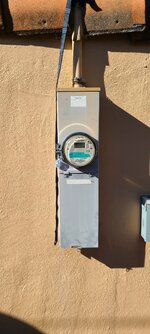
The sub panel and service disconnect are back to back and connected with a metal connector via knock outs.

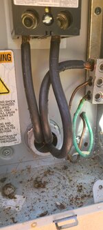
Currently there are three #2/0 wires going from the 200 amp service disconnect to the main sub panel. Passing through the main sub panel are 2 ground wires, which are terminated in service disconnect. One for the ground rods and the other for the solar system. There is no ground in the main sub panel. The ground rod wire certainly makes contact with the sub panel, but has no termination. In the sub panel, neutrals and grounds are sharing the same lugs. I believe I should install separate ground lugs in the sub panel and connect grounds to those lugs.

I want to do this right, so as I pull out the old box and put in a new box, do I need to add a ground connection from the service disconnect to the sub panel? And if so, is #4 what I need to use? And, do I just add a lug to the service disconnect box and terminate it there??

I've attached picture of the service disconnect, the wiring of the disconnect and the wiring of the sub panel.

Thank you!
 

Attachments
  • 20230121_131607.jpg
    20230121_131607.jpg
    732.5 KB · Views: 45
  • 20230121_131622.jpg
    20230121_131622.jpg
    372.9 KB · Views: 37
  • 20230122_112246.jpg
    20230122_112246.jpg
    445.8 KB · Views: 39
  • 20230122_112250.jpg
    20230122_112250.jpg
    370.9 KB · Views: 45
  • 20230121_131511.jpg
    20230121_131511.jpg
    419.7 KB · Views: 47
Last edited:
To avoid these ads, REGISTER NOW!

mm08822

Well-known member
Joined
Jan 13, 2012
Messages
6,266
Location
NJ
I need to upgrade main sub panel which comes off 200 amp service disconnect. I am installing addition solar panels and to meet the 120 rule, will install a 225 Amp sub panel on my 200 amp service to give more busbar room. Currently have a 200 amp rated main sub panel. In looking at how the current electrical system is wired, I think the ground is wired incorrectly. However, the service was upgraded from 100 amps to 200 amp and 21 solar panels were installed in 2007. This was all inspected and approved.

The sub panel and service disconnect are back to back and connected with a metal connector via knock outs.

Currently there are three 2 awg wires going from the 200 amp service disconnect to the XXXX sub panel. Passing through the XXXX sub panel are 2 ground wires, which are terminated in service disconnect. One for the ground rods and the other for the solar system. There is no ground in the main sub panel. The ground rod wire certainly makes contact with the sub panel, but has no termination. In the sub panel, neutrals and grounds are sharing the same lugs. I believe I should install separate ground lugs in the sub panel and connect grounds to those lugs.

I want to do this right, so as I pull out the old box and put in a new box, do I need to add a ground connection from the service disconnect to the sub panel? And if so, is #4 what I need to use? And, do I just add a lug to the service disconnect box and terminate it there??

I've attached picture of the service disconnect, the wiring of the disconnect and the wiring of the sub panel.

Thank you!
I will try to go point by point in the order you wrote them.
  • 120% for a 225A panel will limit you to a 70A max solar input. Does this match you new solar design output?
  • The grounds should not be going through the sub panel. You will need connections in the meter/main for ground rods, water pipe and to the sub panel and also a bond connection to the meter/main enclosure.
  • I can find several issues in both panels. Did the inspector open up either panel?
  • The ****** through the wall connecting both panels together never made it to the sub panel!!
  • There should be 4 wires between the panels unless the conduit/****** was metallic and properly connected to each enclosure. The 3 wires shown look bigger than #2's.......hopefully 2/0.
  • The grd wires from the main panel for electrodes and water pipe should not enter the sub panel. The solar ground wire has no business being in the meter/main. It should terminate in the same enclosure as the 120/240v connection.
  • A grd bar should have been installed in the sub panel and all grounds from branch circuits connected to it. This is where the 4th wire from the meter/main would terminate.
  • Random wires touching metallic parts does not count as an approved connection. Just like the bx without connectors or redheads.
  • Make sure the new sub panel has an isolated neutral bar separate grd bars.
  • #6 Cu or #4 Al is the size of grounding conductor needed between panels.
  • If you can't find a neutral bar for that main disconnect, I would modify it and add more lugs. See what part options exist for this.
  • You probably need an intersystem bonding block connected at the meter/main.

Edit: corrected solar system max input value.
 
Last edited:
OP
B

btscott

Member
Joined
Jan 22, 2023
Messages
5
Thank you for the thoughtful response. Appreciate and agree with most and have purchased all of the things you outlined today. Waiting for the panel to arrive to swap it out.

I'll take your points by point.

120 rule is (Busbar Rating (A) x 1.2) - Main Breaker Rating (A) = Max PV (A). So, 225 amps x 1.2 - 200 = 70amps. I currently have a 4.1 kW system with 30 amp breaker and will be adding an additional 4 kWs which will require an additional 30 amp breaker. 60 amps...

Agree the ground rod ground should not be running through the sub panel. Will move it out and go straight to the Main.

I wasn't there for the inspection, but doesn't seem like they did or they had a few too many that day.

I will be correcting the ****** so it makes proper connection. Seems like the electrician busted out an extra knock out.

You are correct, the wire is #2/0, I didn't add the 0... I'll correct that in my post.

I will be removing the ground for the solar system from the Main and moving it to the sub. This will free up a lug and will put #4 copper ground from that lug in the main to ground bar added to the sub panel. I will separate the grounds and neutrals. Neutrals on neutral bars and grounds on ground bars attached directly to the panel box.

Random wires touching was just me joking, but agree that does not constitute a connection of any sort.

Not sure what you mean by intersystem bonding block, but will look it up and see if its needed.

Again, thank you. Please let me know if you see any errors in my thinking as I move forward with this. Pretty unhappy with the shotty work I received when my system was upgraded from 100 to 200 amps. More unhappy that it wasn't caught in inspection. Most unhappy about the safety issues that this could have provided.

Cheers!
 

wyliesdiesels

Well-known member
Joined
Aug 14, 2012
Messages
20,243
Location
Modesto, CA
wow what a mess. someone totally screwed up that sub

Sub should definitely be 4-wire unless the ****** is connected properly

the bar on the left, that is mounted to the enclosure, should be the ground bar and thus shouldnt have ANY neutrals on it.

likewise, if the bar on the right (cant tell) is on plastic risers, then it is the neutral bar and all ground wires need to be moved off of it to the bar on the left, all white wires on the left bar need to be moved to this bar and the black tie bar between the 2 bars needs to be removed.

Basically the person that did this wiring reversed the function of the bars. totally wrong... at least the bonding strap below the panel board wasnt hooked up.
 
OP
B

btscott

Member
Joined
Jan 22, 2023
Messages
5
wow what a mess. someone totally screwed up that sub

Sub should definitely be 4-wire unless the ****** is connected properly

the bar on the left, that is mounted to the enclosure, should be the ground bar and thus shouldnt have ANY neutrals on it.

likewise, if the bar on the right (cant tell) is on plastic risers, then it is the neutral bar and all ground wires need to be moved off of it to the bar on the left, all white wires on the left bar need to be moved to this bar and the black tie bar between the 2 bars needs to be removed.

Basically the person that did this wiring reversed the function of the bars. totally wrong... at least the bonding strap below the panel board wasnt hooked up.

Both bars are neutral bars. There are no ground bars in the panel. Switching to a Square D 225 amp panel off the 200 amp main. Will be adding 2 ground bars to the new panel.

Sigh... yes its screwed up. Mostly can't believe I didn't catch it.
 

mm08822

Well-known member
Joined
Jan 13, 2012
Messages
6,266
Location
NJ
120 rule is (Busbar Rating (A) x 1.2) - Main Breaker Rating (A) = Max PV (A). So, 225 amps x 1.2 - 200 = 70amps. I currently have a 4.1 kW system with 30 amp breaker and will be adding an additional 4 kWs which will require an additional 30 amp breaker. 60 amps...
70Amps is correct. I was doing mid-night math!!

I have a 7.5 KW system and was able to get by with a 40 amp cb in a 200 amp panel. The rated outputs from both inverters does not exceed 40amps. Check your existing and proposed solar systems. You might be in the same situation and therefor won't need the 225a rated bus panel. Refer to NEC 705.12 (B)(2)(3A).
(You certainly need a new panel to clean up all of the existing issues.)
 
To avoid these ads, REGISTER NOW!

wyliesdiesels

Well-known member
Joined
Aug 14, 2012
Messages
20,243
Location
Modesto, CA
Both bars are neutral bars. There are no ground bars in the panel. Switching to a Square D 225 amp panel off the 200 amp main. Will be adding 2 ground bars to the new panel.

Sigh... yes its screwed up. Mostly can't believe I didn't catch it.
Nope, if the bar is directly attached to the panel enclosure then it would have to be a ground bar as you cant isolate it.

Does the bar on the right have plastic insulators?

EDIT: guess i should put my glasses on. thought the one on the left looked like it was directly mounted to the panel
 
Last edited:
OP
B

btscott

Member
Joined
Jan 22, 2023
Messages
5
70Amps is correct. I was doing mid-night math!!

I have a 7.5 KW system and was able to get by with a 40 amp cb in a 200 amp panel. The rated outputs from both inverters does not exceed 40amps. Check your existing and proposed solar systems. You might be in the same situation and therefor won't need the 225a rated bus panel. Refer to NEC 705.12 (B)(2)(3A).
(You certainly need a new panel to clean up all of the existing issues.)

I will look up the NEC code, but probably best if I just replace the panel and clean up all this mess. I've already bought the panel, supplies and pulled the permit. Again, thank you for you thoughts and advice.
 
Last edited:
OP
B

btscott

Member
Joined
Jan 22, 2023
Messages
5
Nope, if the bar is directly attached to the panel enclosure (like the left one) then it would have to be a ground bar as you cant isolate it.

Does the bar on the right have plastic insulators?

Both of them have plastic insulators.
 
Last edited:
To avoid these ads, REGISTER NOW!
Top Bottom