To avoid these ads, REGISTER NOW!

Advice from the pro's?

e-tek

Well-known member
Joined
Dec 19, 2007
Messages
10,690
Location
Saskatoon, SK
Howdy electricians (Automotive types?).....

You may have seen the wiring mess I'm involved with on the 40 Ford Rod I'm currently building. While I'm quite sure I can get though it and get (most?!) of it working, I know there's many, MUCH more experienced guys than me - so, I thought I'd ask for any bits of wisdom you may throw my way.

I know that's pretty much an open invitation to any dude who's ever twisted a speaker wire together :lol:, but I'm hoping someone with some real world experience may throw me a tip, trick or best practice that can help me do this job in the most proficient and professional manner!

Here's where we are today (copied from my other thread):

It's a universal kit called "It's a Snap" and came with the Rod. Seems pretty good to me, though in doing some research on these kits it would seem "Painless" is the Cadillac of aftermarket harnesses and this one is a mid-line brand. Having said that, I'm not sure what else you'd need: it has a full fuse box, wires for each vehicle section (dash, interior, engine and front end and rear end). All the wires are labelled every foot with where they go. It even has a couple different clips that mate up to either a GM, Ford or Mopar steering column. This rod has a GM column, so I just had to use the male connector that came with and line up the same color wires to mate up with the functions coming from the column (lights, blinkers, horn, etc). It also has a horn relay and blinker (flasher) diodes.

106_2597.JPG


The time consuming part is cutting and connection the wire ends to all the things they control: from head lights to taillights, alternator and gauges - which will take the most work for sure. I was thinking I'll cut a foot or two of the correctly labelled wires, wire the gauges on the bench and then match the pigtails together in the car.

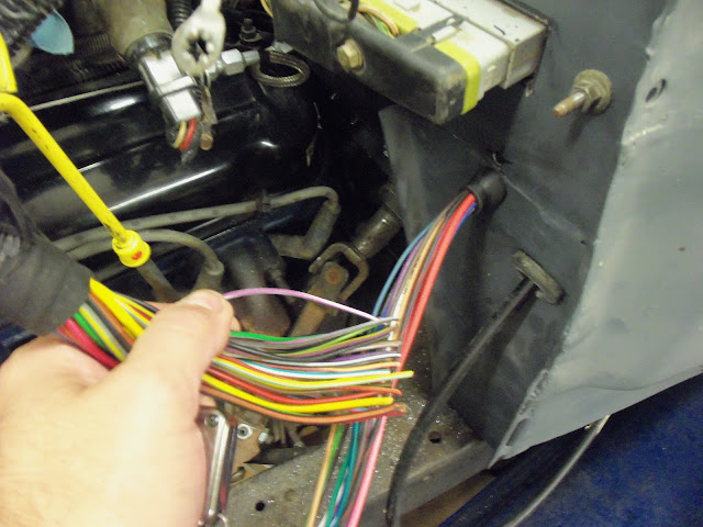
In this case I have to match up the engine management harness with the aftermarket one:
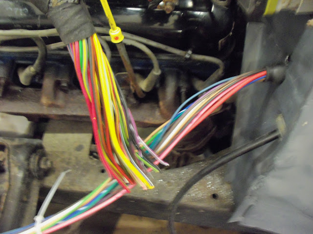
106_2593.JPG


106_2596.JPG


With this project though, the aftermarket harness install is just one piece of the puzzle. As I said above, it all has to be married to the 5.0L EFI harness, a somewhat complicated Vintage Air set-up, as well as power windows, power locks and electric wipers.

Here's what some of that looks like today:

106_2592.JPG


106_2597.JPG


Cheers!
 
To avoid these ads, REGISTER NOW!

trbomax

Well-known member
Joined
Mar 21, 2010
Messages
2,556
Location
starvation lake,mi.
Ive done a few specialty vehicles,hand buil`t motorhomes,semi tractors,rods,and a bunch of boats.All that being said,Ive never used a quickie harness,I always did the whole thing from sctrach ,laid out on the floor,then installed and terminated it.This results in pages of drawing and diagrams,but its how I learned to do it 50 yrs ago. The problem I see with the premade harness is that its too genaric. If I were doing what you are doing I would first make a drawing of every wire with color and size,and of course what it does in the whole car. Then I would run (or extend) everything to a common location.Then do the same thing with that "harness" you have and run it to the same location. Get an apropriatly sized plastic box and some old school #10 2 pole terminal strips and treminate all of the existing wires in the car.Then run the "harness" ends to the proper lugs on the other side of the terminal strip.Again,make a drawing with all the colors ,locations and purposes on it. Now you can add whatever other wires you need to do what must be done.With this method you can ring out each function or load and easily move things around as required. You will need couple boxes of ring toungs,I buy the uninsulated ones from ww grainger,use a stakeing tool on them and solder them.Dont forget the heat shrink tubeing before you terminate them. This makes for an aircraft quality panel that can easily be diagnosed in the future. The problem with it is its very expensive to do that way in terms of both time and materials. Over the years Ive done a bunch (50 or more)of Hatteras Yachts this way when I worked for what was then the biggest Hatteras dealer on the lakes. Its how I was taught to do it and so anything I wire gets done that way.

edit) for extending a wire I prefer to use a bare **** splice connector,lightly staked ,soldered,and then heat shrink. NEVER put two joints like this next to each other or within 2 " of each other in a harness.
It is also important to recognize the "crimping" is not the same as "stakeing" and should never be used in anything other than lampcords or speaker wire.
To put things in perspective,when I would wire a flybridge on a motor yacht there would be a 3" dia pipe running up from the engine room,between decks,and to the roof with 200 or more separate wires running thru it,all breadboarded at each end,so a car with 20 circuts is a cake walk!
 
Last edited:

tdkkart

Well-known member
Joined
Jun 17, 2006
Messages
6,887
Location
Eastern Iowa
The biggest trick is to not let it overwhelm you. It looks like a hell of a mess, but it's really not. Go at it slow, one component at a time, one wire at a time. Keep it as neat and tidy as possible, don't be afraid to pull a wire back and re-route it if you don't like it.
Leave plenty of slack for future work. Solder and shrink sleeve everything.

Tell you what, you do my body work projects, I'll handle you wiring projects. Wiring I enjoy, body work *****.
 

trbomax

Well-known member
Joined
Mar 21, 2010
Messages
2,556
Location
starvation lake,mi.
I think you intimidate people because of the high visibility of your projects! Nothing personal at all, thats just my 02! Me,I'm not intimidated by anything! You do have a real birdsnest though!
 
OP
E

e-tek

Well-known member
Joined
Dec 19, 2007
Messages
10,690
Location
Saskatoon, SK
I think you intimidate people because of the high visibility of your projects! Nothing personal at all, thats just my 02! Me,I'm not intimidated by anything! You do have a real birdsnest though!

I just thought there'd be some guys here that had done many of these before (like yourself), but I also went to other sites and got some good advice - like zip-tying "like" wires every 6 inches, using junction boxes for running grounds and gauge lights, not grounding door motors to the door (but run them back inside cab to ground),

Ya - that was just after unraveling all the ******* wires from their respective boxes and such. Once they "relaxed" I did get a lot of that cleaned up . I bundled all the gauge, light, under-dash and accessory wires into sub-units and will also make a few small wooden backer boards to mount relays on and also to attach wires to before they go to another locations - to guard against pulling.

Cheers!
 

Lotek

Well-known member
Joined
Dec 9, 2007
Messages
9,098
Location
Los Angeles, Ca.
I use zip-ties to rough out harnesses, when I am sure everything is where it's going,I tape it and cover with either conduit or a layer of kevlar tape. You want to make absolutely sure the harness isn't going to move around and chafe. Weld or braze a couple of ground studs in. Properly crimped weatherpack connectors for anything exposed to the elements. One thing that makes a nice looking harness where it's visible is to use the larger, non double wall heatshrink tubing over the harness,overlapping pieces where wires separate out,then install it in the vehicle and form it the way you want before using a heatgun to shrink it all at once.Not a good idea if things are going to be switched around,but it looks good for sub harnesses. If you don't already have them, get a Powerprobe3 and a butane soldering iron, along with the proper tool for whatever crimp terminals you use.
 

ddawg16

Well-known member
Joined
Jul 11, 2008
Messages
21,005
Location
S. California
Yep....keeping the wires organized is one of the keys....

One thing to remember....for the most part, the EFI portion for the engine is pretty much a self contained harness.....when I did the FI SBC swap into my jeep.....there were actually only 6 wires that I had to hook up to the engine harness....bat, ign, start, brake, gnd and CEL.

The engine was easy.....it was separating the chassis harness from the old engine harness was the hard part.

Some key wires you need to identify....Ign...start....acc....and if you have the right ign switch....lamp test.

The FI setup will most likely have outputs for Tac, CEL, RPM, etc. You need to find those if your using those items. On my engine.....I just installed a second temp sending unit and oil pres sending unit on the engine so I could use my stock jeep gauges.

And....yes...Painless is the way to go....outstanding products.

One last thing.....make sure you have a really good ground.....it's so easy to overlook that part.

Too bad your not closer....I'd love to help you wire that up.....I figure we could knock it out in less than one 12 pack.
 

nanofrog

Well-known member
Joined
Mar 1, 2012
Messages
1,323
I know most find it hard to believe, but a properly performed crimp terminal is better for automotive use than soldered connections as there's no wicking of solder under the wire insulation (creates a spot where the wire will crack, and eventually break under vibration).

The trick, is getting it done right, which is a combination of the correct tooling, proper terminals for the job (i.e. don't use insulated terminals, but rather uninsulated ones and/or open barrel types with adhesive lined heat shrink <keeps out moisture to avoid corrosion>), correct wire strip length, making sure the wire is clean, and locating the terminal properly in the die nest prior to crimping it. When all of this is done right, the wire actually welds itself to the terminal (called a cold weld).

Also make sure the harness is well supported to reduce the flexing due to vibration.

BTW, Metripack and Weatherpack are both open barrel types with sealed connectors.

As per tooling, you're best to use a ratcheting type crimp tool, not the plier types, as it provides consistent pressure every time, which is critical in getting the wire and terminal to weld to one another.
 

trbomax

Well-known member
Joined
Mar 21, 2010
Messages
2,556
Location
starvation lake,mi.
If you do the soldering correctly there wont be any of it under the insulation.I let the bare wire stick thru the terminal sleeve 1/16" and apply my solder tip to the terminal at that point. When the color changes or flashes ,add a very small ammount of solder and get the heat off of it. Ive seen a lot of gloopy solder jobs with melted insulation and if thats how its being done,yes there will be problems down the line. I dont think it matters anyway because in over 50 yrs of doing this Ive never seen a wire cracked and broken from soldering. Seen some broken that were not soldered but in any case if the harness is secured properly its not going to be an issue.

edit) you have to have a high cap gun that gets hot so you can get in and out quick,kinda like fusion welding with a tig.I use an 800 watt weller on anything up to #12, but that is definitly its limit.
 
Last edited:

nanofrog

Well-known member
Joined
Mar 1, 2012
Messages
1,323
If you do the soldering correctly there wont be any of it under the insulation.I let the bare wire stick thru the terminal sleeve 1/16" and apply my solder tip to the terminal at that point. When the color changes or flashes ,add a very small amount of solder and get the heat off of it. Ive seen a lot of gloopy solder jobs with melted insulation and if thats how its being done,yes there will be problems down the line. I don't think it matters anyway because in over 50 yrs of doing this Ive never seen a wire cracked and broken from soldering. Seen some broken that were not soldered but in any case if the harness is secured properly its not going to be an issue.

edit) you have to have a high cap gun that gets hot so you can get in and out quick,kinda like fusion welding with a tig.I use an 800 watt weller on anything up to #12, but that is definitely its limit.
The info I posted on crimp v. solder was based on production conditions/results, as the skill level required for proper solder joints for wire harnesses is more involved than crimping. Thus the crimp terminals have a better consistency for creating good joints (less rework required).

Either way, it comes down to a mix of skill, tools, and materials (i.e. cheap Chinese terminals vs. good ones such as Panduit, T&B, ...; same goes for cheap solder that may not have enough flux in it vs. good solder such as Kester or Multicore).

BTW, with your technique, do you mean you're applying the solder on a small bit of exposed copper wire between the tail end of the connector and the wire's insulation?

If so, I'd recommend not doing this, and use connectors with a gap in the middle (uninsulated types), and limit the amount of solder applied (presumes no crimp prior to solder, as you don't want to solder a crimped terminal - it's actually a weaker joint due to the annealing of the copper in the terminal <can't control the heat properly on your Weller soldering gun>).
 

tatra

Well-known member
Joined
Dec 2, 2007
Messages
4,785
Location
pirate contest city
only advice i can give that has served me weel was something i gleaned from a book on doing harnesses and that is to mock up what ever you are doing with cheap multicolored fishing lines ,twines, strings etc and give yourself at least 12 inches at the termaination points........i have also used telecommunication cables that have different hash marks on them for id 'ing different circuits....... a one foot cut off should so you fine and when you run out of different combos . you just double up.........ex. , purple with black hash mark already used , the next circuit is marked with 2 wires ........i have only built very simple harnesses but these tricks have served me well as electrical to me is voodoo at the best of times
 

trbomax

Well-known member
Joined
Mar 21, 2010
Messages
2,556
Location
starvation lake,mi.
The info I posted on crimp v. solder was based on production conditions/results, as the skill level required for proper solder joints for wire harnesses is more involved than crimping. Thus the crimp terminals have a better consistency for creating good joints (less rework required).

Either way, it comes down to a mix of skill, tools, and materials (i.e. cheap Chinese terminals vs. good ones such as Panduit, T&B, ...; same goes for cheap solder that may not have enough flux in it vs. good solder such as Kester or Multicore).

BTW, with your technique, do you mean you're applying the solder on a small bit of exposed copper wire between the tail end of the connector and the wire's insulation?

If so, I'd recommend not doing this, and use connectors with a gap in the middle (uninsulated types), and limit the amount of solder applied (presumes no crimp prior to solder, as you don't want to solder a crimped terminal - it's actually a weaker joint due to the annealing of the copper in the terminal <can't control the heat properly on your Weller soldering gun>).

I dont even HAVe any insulated terminals in my box and the heat I apply to the terninal right where the wire sticks out. like I said,Ive probably done close to 10k of them over the last 50+ yrs and never had a comeback,so it works for me.
 

ddawg16

Well-known member
Joined
Jul 11, 2008
Messages
21,005
Location
S. California
As most of us know, every connection is a potential failure...the less connections, the better....

On my jeep, I installed a bank of terminal blocks....gives me a good place to terminate wires....and easily removed.....

I have the flexibility to install jumpers to create bussed power....and have them individually fused.

10-12-10006.jpg
 
OP
E

e-tek

Well-known member
Joined
Dec 19, 2007
Messages
10,690
Location
Saskatoon, SK
Now THIS is what I was looking for!!! Thanks guys!!

Lotek - great ideas on welding in some wire-holders. I'll definitley do that as right now there are none, it's a clean slate if you will. I did buy a good stripper with decent crimp capability, but I'll definitely be getting a dedicated crimper. On the non-double walled HS, can you get it in long lengths?

John - your EFI info is golden. I was looking at the harness and schematics and did notice a lot of it seemed stand alone. How many of the 25-odd wires in the EFI harness you had weren't used in the end? That teminal block - is that for unused wires? Also, what's "CEL"?

For you guys talking quality connections - how do these look and are there better ends I could use? For the gauge grounds I had planned on terminating them all together in a common ground - should I do that and if so, should I use a terminal block or can I just put them all on one screw into the frame that backs up the vintage air unit and dash? I want to be sure the grounds stay solid!

106_2615.JPG


106_2622.JPG
 
To avoid these ads, REGISTER NOW!

ddawg16

Well-known member
Joined
Jul 11, 2008
Messages
21,005
Location
S. California
CEL = Check Engine Light.

Of the unused wires in my harness.....Cruise control....outputs for the instrument cluster....(to keep my original jeep gauges I used the original sending units)

The most difficult part for me was the power....whoever yanked the harness out of the donor vehicle cut the harness at the fuse block.....so that part took some chasing down. There are about 6 fuses just for the engine....injectors, transmission, fuel pump, O2 sensor, Inst cluster, computer....etc, etc. Your setup might differ a little.

The terminal block was so I had a convient place to land some of the wires that did not have a place in the original jeep setup....for example, the brake switch is now two outputs....one for the lights, the other for the computer (to disengage the lock up converter). As you have most likely noticed, the typical auto wiring is point to point. When you do an EFI into an existing chassis....point to point is not so easy....that is why kits like the Painless are so nice....the solved the problem for you.

Your connections look good.....as noted above...you don't want the solder to wick up under the insulation....if it does, the soldered part does not bend...but the wires do....under vibration conditions, it will cause the wire to break right where the solder ends.

If you do any high tech soldering...they actually make a tool that helps prevent the solder from wicking past the tool.
 

abnorm

Well-known member
Joined
Jun 24, 2006
Messages
77
Location
Orlando
CLOTHESPINS.........

I've used spring clothespins to sort out the harness....identify particular circuits/wires by writing on the pin......hold wires to a bundle while determining length/path......

Then add your tie wraps and over wrap when finished
 

tdkkart

Well-known member
Joined
Jun 17, 2006
Messages
6,887
Location
Eastern Iowa


What little bit I can see here suggests that you're using a touch too much solder. As a 27 year employee of a US government electronics contractor, I've been through my share of solder certification classes. Too much solder is a no-no.
In stranded wire connections to posts or terminals, the proper amount of solder will allow you to see the outline of the wire strands. If you can't see the strands of the wire you've got too much solder in the connection.
We don't solder crimped connectors, however we use calibrated and tested dedicated crimpers for every terminal type. Crimped connections are periodically tested for tensile strength.

I like these crimping pliers for general automotive work, along with a dedicated stripper.

Crimper:
http://www.channellock.com/crimper.aspx

Strippers, available in various wire sizes:
http://www.channellock.com/wire-strippers.aspx
 

nanofrog

Well-known member
Joined
Mar 1, 2012
Messages
1,323
What little bit I can see here suggests that you're using a touch too much solder.
I'd have to agree.

I like these crimping pliers for general automotive work, along with a dedicated stripper.
I prefer the ratcheting types as the pressure applied is consistent. Too much of a chance for operator error on pressure with the plier types IMHO, as the operator may not know the difference between an under or over compressed crimp when it's close.
 

MBfreak

MEMBER EMERITUS
Joined
Dec 10, 2010
Messages
2,301
Location
Linkoping , Sweden
I very much like the input from tdkkart. I have been into industrial, auto, maritime electrics for a looong time, and second his well described procedure for soldered connections in automotive/maritime applications.
The " stiff stranded wire syndrome due to solder wick action" that leads to a a wire failure is news to me. I do understand the general description but do not understand why anybody would fill the wire with solder. All thats needed is that about half the length of the wire in the lug is soldered in. With a bit of practice this is easy to get right.
Crimped connections are great and used extensively in industry. In automotive applications, especially if you live in a cold climate with lots of salt laden moisture, the risk of getting green copper oxide creeping into the crimp on the surface of each wire is not to be underestimated. Covering a crimp joint with glue-reinforced shrink tubing can help some.
I have recently heped a friend with an italian exotic ( DeT Pantera-72) The cable harnesses for front and back runs in the wheel housing, and needs to be well dressed. I made up new harness parts with wires in groups , each group in an individual pvc-tube.
They were then bunched together in a polyaramid woven "stocking" of the type used to protect hydraulic hoses from being damaged.
Very strong and flexible and can be run even in very short curves without being to bulky.

Good luck with the job, etek.

Ola
 

Attachments

  • mini-Framstam Pantera 001.jpg
    mini-Framstam Pantera 001.jpg
    121.2 KB · Views: 13

ddawg16

Well-known member
Joined
Jul 11, 2008
Messages
21,005
Location
S. California
The art of wire soldering is a lot like copper pipe sweating....and once you are shown the right way....it's easy....

Contrary to popular belief, more solder is not better....in a good joint, the wire strands are easily decernable....in the case of soldering on a ckt board....The strongest joint is not the one with a glob of solder on it...but rather a lean and clean joint.

One suggestion to getting good joints....use a damp sponge to wipe the tip of the soldering gun before you apply it to the wire. The following is my usual method.

1. Wipe tip with a damp sponge
2. Tin the tip with a small amount of solder
3. Touch the wire...as soon as I start to see the solder wick to the wire, I apply more solder. If the temp is right, the wire will '**** up' the solder. At this point....remove the iron.....it's done.

If apply too much solder, this is when it starts to wick up under the insulation....not good...

Someone mentioned that if you crimp, you don't need to solder.....True....but it does not hurt anything if you do. I frequently solder crimp connnections...especially on my jeep. But for me, the crimp is really there to hold the wire while I solder it.

One other trick....tin your wire first before you solder it.....it helps to hold the strands together as you insert it into the connector.
 

theoldwizard1

Well-known member
Joined
Feb 22, 2011
Messages
43,602
Location
SE MI
With this project though, the aftermarket harness install is just one piece of the puzzle. As I said above, it all has to be married to the 5.0L EFI harness, ...

The only thing the EEC harness should connect to is power, key-power and ground. The power connection should be a close to the battery as possible. There are several "grounds" in this system including a separate "case ground" (usually the case is grounded through the bracket and the vehicle sheet metal). Power ground should go directly to the battery. Do not rely on chassis ground. There is probably an ignition ground and a EGO ground.

Those harnesses changed over the years, so a lot of this depends on what model and year the donor car was. Try and find a wiring diagram.
 

theoldwizard1

Well-known member
Joined
Feb 22, 2011
Messages
43,602
Location
SE MI
Yep....keeping the wires organized is one of the keys....

Use loose zip ties to keep things organized. Colored zip ties would help keep like things organized.


Personally I like the look of the "factory" harness that are wrapped in 3/4" PVC tape that has no glue. Hard to find on the Internet, especially at a reasonable price. The finish with friction tape, but you could just use a good quality tape like 3M 88.
 

nanofrog

Well-known member
Joined
Mar 1, 2012
Messages
1,323
The art of wire soldering is a lot like copper pipe sweating....and once you are shown the right way....it's easy....
For those interested, Pace put up a soldering tutorial series on YouTube. Bit old, but done very well and still quite useful IMHO.

Someone mentioned that if you crimp, you don't need to solder.....True....but it does not hurt anything if you do.
Unfortunately, this isn't entirely true. Take a look here; particularly #2. It comes down to soldering skill, but if you're using the right terminal and tooling to begin with, you're actually increasing the odds of a failure by going behind and soldering it as well.
 

ddawg16

Well-known member
Joined
Jul 11, 2008
Messages
21,005
Location
S. California
Nano...that reference is from Panduit.....who wants you to buy their crimper.....

Is crimping terminals better than soldering them? Some young engineers here claim soldering is better.


There are several reasons why a crimped termination is favorable to a soldered one:
1.) A crimped installation physically joins the wire to the terminal barrel by the compression of the dies in the tooling. This is done exactly the same way each time. Soldering is only as consistant as the person doing it.

2.) A crimped installation also causes the barrel to grip the wire. (Every time with a tool) If the wire and terminal are not heated evenly during soldering, the solder will bond firmly to one and not the other, resulting in low pull out forces. Crimped installations offer better pullout forces.

3.) There may be UL issues involved with moving to solder. Most manufacturers get their UL listing with their tools and product used as a system. You may be using a UL listed terminal, but soldering doesn't make it a UL connection.

4.) The young engineers may not understand the impact and function of labor costs. A crimped terminal takes about 5 seconds of labor to complete, a soldered connection can take 2 to 3 minutes. Why would they want to increase their installation time by 24 to 36 times?

5.) Crimp tooling is a one-time purchase. Soldering will require continual purchases of expendable material (solder). This adds further to your costs to manufacture.

I am an Electrical Engineer by education and would never consider replacing a physical, UL listed crimp with a soldered connection.

Sorry...but the author is very biased......

I have a buddy who is and expert on aircraft wiring systems....I'll ask him.....
 

nanofrog

Well-known member
Joined
Mar 1, 2012
Messages
1,323
Nano...that reference is from Panduit.....who wants you to buy their crimper.....
I can see where you're coming from, but that doesn't change the fact it's genuinely relevant, regardless of the crimp terminal manufacturer or crimp tool manufacturer (even when they have the same label, they're not made by the same company).

Now as you highlighted, the key to a good solder joint is the skill of the operator doing the soldering. But what you need to realize, is that even in the hands of a highly skilled person, there's enough variability in the results that they aren't as consistent as the crimp method using the correct tooling for the terminal being used, and it's calibrated correctly (statistically speaking, crimp terminals have a higher reliability than soldered terminals which is determined by a lot of testing).

BTW, most of the best crimpers are made by Pressmaster (Molex, T&B, Emerson, TE Connectivity <formerly Tyco>, and Xcelite just of the top of my head), and I think NWS makes them for Panduit (same source if they aren't, and that frame even shows up as at least one Wiha <same frame as the CT-1550 or CT-1551>). So a good one tends to work on multiple brands of terminals of the same type (standardized terminals).

I have a buddy who is and expert on aircraft wiring systems....I'll ask him.....
Similar to my background (Component Eng. Dept @ Lockheed). Prior to starting there, I didn't realize that the crimp terminals were actually better than soldered joints on a consistent basis either (mentor I had as an intern proved it to me by performing various tests, with the pull tests being the most visible indication he wasn't full of it :p).

Definitely opened my eyes... :thumbup:
 
OP
E

e-tek

Well-known member
Joined
Dec 19, 2007
Messages
10,690
Location
Saskatoon, SK
Thanks guys - GREAT information.
Now, since you guys are back and forth on crimp vs solder, I'd ask you to look at it in this context: the amount of wiring I've done over the years is about 1/50th of all my time in the shop. I want to do the best job possible - with the least chance at a connection going bad (coming loose). SO - wouldn't soldering a crimp be much less likely to come loose than a crimped joint? I'd guess yes.
 

MoonRise

Well-known member
Joined
Nov 5, 2010
Messages
4,045
Location
NJ
SO - wouldn't soldering a crimp be much less likely to come loose than a crimped joint? I'd guess yes.

Done right, a crimped joint is NOT coming loose.

If it really makes you 'happy', go ahead and correctly solder your wires. But it's not needed with a crimped joint.

re: solder joints and soldering.

Repeating some of what has already been said.

Use a soldering iron with a clean tip. Let it heat up, apply some solder/flux to it, wipe off on damp (water) sponge, so that tip is clean and tinned. Repeat if needed until tip is clean, shiny, and tinned. Neglected tips may have to be 'scrubbed' while hot with steel/copper wool and some extra flux/solder until clean, shiny, and tinned.

Apply -tiny- bit of solder to tip, apply tinned tip to the 'heavy' (thicker, bigger, etc) side of whatever is being soldered together (in plumbing, that means you apply the heat to the fitting and NOT the pipe itself), touch tip of solder to the 'cold' side (the pipe in plumbing, the tip of the wire protruding through the connector barrel in your case), when the solder just melts apply just enough to do the job and then remove heat and the solder roll, let cool without moving, done. Wipe off flux (you are using electrical solder with resin flux, right? Not some acid-flux or such for plumbing or metal-working?)

If you see the solder wicking up past the 'wire-side' of the crimp (as opposed to the 'terminal' side), then you applied too much heat and solder.

I'll be rather picky on you. Cut the wire ends more neatly (looks a bit 'sloppy' in your crimped-but-not-soldered pictures). Insert the wire until just past the terminal side of the crimp barrel (again, some of your crimped picture look like the wire is protruding too far past the crimp barrel). It looks like you might have gone a little overboard on your crimping pressure (some of the barrels look banana-shaped and the crimp indents look a bit on the deep side). Your shrinkwrap tube overlap on a few of the finished connectors looks a bit too short on the overlap onto the wire insulation.

+99 on getting (or putting in) a good ground connection. If need be, connect a bunch of ground wires together (terminal block or whatever) and then run a 'common' (thicker!!) ground wire to the actual grounding point.

Don't get overwhelmed by the spaghetti. Identify what wires go where and do what, temp 'bundle' them together, temp route the wire bundle (original and the new harness wires) to determine routing and layout and mounting (wire ties, loops, whatever), then make connections.

Fuse block? Make sure that is in there first and route wires to/from as needed. Don't overload circuits (the wire gauge and the fuse have to 'match', don't put too many things on a circuit, etc). Fusible links or individual in-line fuses for things if needed (just don't bury in-line fuses all over the place, make it 'obvious' and easy if you do put an in-line somewhere, like for a radio/amp). About the only thing that doesn't get fused is the starter, everything else gets fuse-protected.
 

Attachments

  • 106_2615.JPG
    106_2615.JPG
    55.2 KB · Views: 8
  • 106_2622.JPG
    106_2622.JPG
    43.1 KB · Views: 7

nanofrog

Well-known member
Joined
Mar 1, 2012
Messages
1,323
SO - wouldn't soldering a crimp be much less likely to come loose than a crimped joint? I'd guess yes.
Assuming the crimp was done correctly, you'd actually weaken the termination by adding solder (heating/annealing the copper terminal weakens it, and shear the cold welds), at which point you're essentially relying on the soldered joint alone.

Between the two methods, a proper solder joint is harder to perform. Proper crimping requires less skill (get the strip length right, make sure the copper wire is clean, and how to locate the terminal in the die). While a good solder joint requires most of that plus additional aspects of the skill level (clean wire, strip length, how much to heat the terminal and wire <must be even and not vaporize the flux or carbonize it <takes on a carmel to black color>, how much solder to use, and don't disturb it if it's non-eutectic <such as 60/40> until sufficiently cooled).

Soldering also takes additional supplies (solder, sponges, tips, heating elements, flux if either the solder doesn't include it or doesn't have a sufficient quantity), and is just as expensive or more for a proper temperature controlled iron (sorry, but the butane powered torches aren't temperature controlled, making it much harder to get the heat right - not impossible, but means the skill level required is even more important).

Please understand, I'm not selling anything, and both have their proper applications. Just that for automotive wiring, crimping is a better way to go for consistently reliable results.
 

ddawg16

Well-known member
Joined
Jul 11, 2008
Messages
21,005
Location
S. California
Ok....just had a chat with my friend.....he is the engineer over the cockpit of the C17.....sort of knows what he is talking about....

So as to not misconstrue what he said....

Soldering is good but it's time consuming and sometimes sloppy. You also have to be qualified to solder. Most electrical connections are done through crimping. Wires are crimped onto pins, then are locked into the cavities of the connector...conversely, on the other side, wires are crimped onto sockets, then are locked into the cavities of the mating connector. Problems occur when the pins/sockets are not locked properly, causing an intermittent signal/power or not crimped to the correct setting, causing high resistance. Long story short, most common practice is using crimp method with correct dies for crimping...most reliable. Are you looking for a particular application? But sometimes soldering is the only way to go...
I'm rambling...too late in the evening to talk shop for me.

Key point here....."if done right".....

As with any system....it's only as good as the person doing it.

Me? I know how to solder...hence, it's the connection of choice for me....and I have the right tools.

So....lacking the proper soldering training....yea....crimping would be the connection of choice.....assuming you have the right crimping tool.....

BTW....good thread....lots of good info.
 
OP
E

e-tek

Well-known member
Joined
Dec 19, 2007
Messages
10,690
Location
Saskatoon, SK
After starting this thread -as well as watching the soldering vid series listed above and others - I have learned a TON of good info! Hopefully many others have too. In the end I;m with John - I'll still be soldering my stuff, trying to do it right of course, just because i've seen too many crimped joints come loose on so many applications.
 
To avoid these ads, REGISTER NOW!
Top Bottom