To avoid these ads, REGISTER NOW!

Can this 240 V motor be reversed ?

halexh

Member
Joined
Mar 7, 2020
Messages
5
Location
California
Trying to get this motor that was removed from a 2475 IR compressor to work on my Quincy 325 and need to reverse its rotation. It is wired for CW rotation and I need CCW.

I believe it is a 7.5hp WEG but there are no wiring diagrams on it. The motor has 3 wires coming out of the wiring box. It has 2 Start Capacitors wired in a series I think and 1 Run Capacitor they are all wired to the Starting Winding and the Running Winding looks to be wired directly to L1 and L2. Not sure if this can be reversed just trying to make sure I am understanding it correctly.

The wires are only 2 colors blue and grey the grey wires run between capacitors and the throw out switch where as the blue wires seem to be the winding wires. 2 heavier gauge wires are connected directly to the two hot wires L1 and L2 and the other two are connected to the Run Capacitor and I am guessing the other winding.

Any help or info is appreciated at this point.
 

Attachments

  • image0 (2).jpg
    image0 (2).jpg
    82.8 KB · Views: 49
  • image1 (1).jpg
    image1 (1).jpg
    143.4 KB · Views: 38
To avoid these ads, REGISTER NOW!

Terry D

Well-known member
Joined
Mar 25, 2015
Messages
2,202
Location
St. Louis, MO.
To reverse rotation on a single phase motor, you have to reverse the polarity to the start winding. You will need to find the two wires to the start winding and reverse them, if this is possible. Not all motors are reversible.

Maybe this will help

 
Last edited:
OP
H

halexh

Member
Joined
Mar 7, 2020
Messages
5
Location
California
To reverse rotation on a single phase motor, you have to reverse the polarity to the start winding. You will need to find the two wires to the start winding and reverse them, if this is possible.

That is my general understanding as well just not quite sure how to accomplish that.

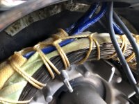
In the second picture the 3 wires on the left are marked T1/U1(10gauge),T8/V3(12gauge),T5/V2(12gauge) and the one on the right is T4/U2(10gauge).
 
OP
H

halexh

Member
Joined
Mar 7, 2020
Messages
5
Location
California
I watched the Compressor Source video earlier as well as another one by woodgears.ca can't post links yet.

Just not quite sure how to switch T5 and T8 they both go on to the Run Capacitor terminals not sure if the capacitor has a positive and negative I tried switching their terminals but it didn't change anything.
 
To avoid these ads, REGISTER NOW!
OP
H

halexh

Member
Joined
Mar 7, 2020
Messages
5
Location
California
I have rewired other motors where there is a separate panel to use wingnuts to combine different wires in order to change a motor from low to high voltage or to change its rotation.

This motor has the panel that I have pictured with the 3 capacitors in it. Out of that panel come out 3 wires that go directly to the magnetic starter White/Black/Green.

The wire within the panel are labeled T1/T4 connected to the magnetic starter so I am assuming they are both hot and T5/T8 are connected to the Starting Capacitor. Then all four wires go inside the actual motor and to the windings which is the second picture and I have explained above which wire is which in the second picture.
 

Terry D

Well-known member
Joined
Mar 25, 2015
Messages
2,202
Location
St. Louis, MO.
Not all motors are reversible. If the leads from the start windings are not accessible, this will be hard to next ti impossible to do. The start winding will have a higher resistance. In some motors these two leads are Z1 and Z2. These two leads need to be switched, if they are accessible

Sent from my SM-G960U using The Garage Journal mobile app
 
OP
H

halexh

Member
Joined
Mar 7, 2020
Messages
5
Location
California
Not all motors are reversible. If the leads from the start windings are not accessible, this will be hard to next ti impossible to do. The start winding will have a higher resistance. In some motors these two leads are Z1 and Z2. These two leads need to be switched, if they are accessible

The second picture is the 4 leads coming from within the motor. I am trying to figure out if the 2 wires that are together are connected to each other under the white insulation and if that would be one of the wires that needs to be switched.

When measuring the resistance on the wires I am getting 0.6 ohms on what I think is the run winding and 1.5 on the lighter gauge wires which I am guessing is the start winding.

Not sure if those readings are correct for a 7.5 hp motor.
 

dogdog

Well-known member
Joined
Nov 15, 2011
Messages
12,711
This is the link, it have a wealth of info... you'll have to take into account of your run caps... how they fit into the pic... and do your own diagram then figure out which one is your Starting coil...

https://www.practicalmachinist.com/...please-wiring-switch-motor-257832/index2.html


This was my link for the DP motor I think... works but does not fit your situation 100%. all you have to figure out is how to flip only that W3 (starting coil) on your motor connection wise... .. and of cause YMMV ...

https://www.garagejournal.com/forum/showthread.php?t=361242&highlight=motor


Objective is to identify the starting coil W3 and reverse ONLY the connections for the starting coil connecting to L1 and L2... (do not reverse the running coils)...

YMMV disclaimer... might involve digging into embedded connections inside...don't do it if you are not comfortable with it...

hope this clarify a bit better....@4AM.. delete some typings.. if I kept the long winded version, might cause more confusion.....

pretty sure you can figure it out from that diagram...
 
Last edited:

wyliesdiesels

Well-known member
Joined
Aug 14, 2012
Messages
20,258
Location
Modesto, CA
I watched the Compressor Source video earlier as well as another one by woodgears.ca can't post links yet.

Just not quite sure how to switch T5 and T8 they both go on to the Run Capacitor terminals not sure if the capacitor has a positive and negative I tried switching their terminals but it didn't change anything.

No positive and negative on A/C power or these capacitors. Its power in and power out.

DC capacitors have polarity and are marked with positve symbols vertically down the positive terminal side.
 
To avoid these ads, REGISTER NOW!
Top Bottom