To avoid these ads, REGISTER NOW!

Craftsman 6" "Alien Head" Bench Planer - Disassembly, Blade/Table Setting, and Fence Replacement

Placeholder17

Well-known member
Joined
Feb 25, 2024
Messages
107
Location
Maryland
I finished setting up a 1950's-60's Craftsman 6" planer (not jointer...) that I bought two months ago. I got the planer without a stand or motor, and the seller had removed the knives for sharpening but then presumably found them difficult to install/align and never put them back in.

Externally, it looked great with a fresh coat of enamel, but internally the spindle was rusted all over and somehow the last person to fiddle with it had managed to install every single set screw (spindle, pulley, bearing shims) off of the machined flats, leaving burrs and gouges everywhere, and put the one pointed set screw in the wrong hole.......... I had to spend way more time with a hammer and punch than I was expecting. The bearings were of course dry and had to be cleaned and repacked.

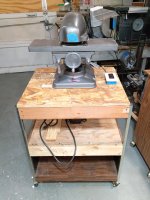
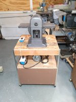
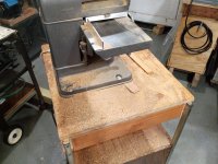
I threw it on a rolling food cart from the thrift store (after a lot of framing upgrades with plywood and 2x4s) with a 1/2 HP 3450 RPM motor. I used a 5" drive pulley on motor per the original manual.

Here is how the head assembly works as manufactured:
  1. Bearings are slip-fit on the spindle shaft
  2. Cutterhead is slip-fit on the spindle shaft
    1. Cutter head has two set screws landing on flats on the shaft
  3. Bearings are a tight slip-fit into their bores in the head casting
  4. Bearings and spindle are locked in place axially as follows:
    1. The rear bearing shim/cover (next to the belt) has a full-perimeter groove into which a pointed set screw locks, setting the reference point for the cutter head/bearing assembly
    2. A pair of inner slip-fit bearing covers slide on the shaft on each side of the cutter head.
    3. The front bearing cover is pushed from outside in to press all of the covers and the spindle against the rear bearing, which is held in place by the notched shim/cover locked by set screw.
    4. The front bearing cover is then locked in place by a set screw.
It is possible that shimming washers may be missing from the spindle:
  1. I found that that after reinstalling the head as described above, the front bearing had moved slightly outside of the bore.
  2. Perhaps there were missing washers or shims.
  3. I pulled everything apart and added (4) 1/2" fiber washers to the rear side of the spindle, so that after reassembly the bearings were fully recessed in their bores and the inner bearing covers sat partially inside the bores, keeping out dust.
  4. I put all the fiber washers at the rear to push the cutterhead away from the column to maximize space for adding a fence
The planer came with both kickback preventing assemblies, but the spring had broken off on one of them.
  1. The spring is simply a bent piece of spring steel
  2. I ran to the local flea market, bought one of the innumerable rusty hand saws, and cut out a little piece with metal shears, which I then bent carefully in a vise using pliers.
  3. The kickback assemblies work great. You don't have to worry about constantly pushing on the wood while feeding. You can take your hands off, even with only one assembly engaged, and the wood won't budge.
Aligning the blades is a pain....
  1. The manual says to align the cutter head to the table and then align the blades to the table with a blade-setting jig that that has disappeared from the earth (no luck trawling Ebay).
  2. Here is the alignment procedure that worked for me:
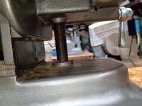
    1. Remove the head casting. The bolts are nearly impossible to reach from the open back of the column casting. It's far easier just to stack socket extensions and reach up from below the whole planer's open base.
    2. Stack a set of parallels (I had 1/8" thick parallels) on the flats of the cutterhead, and align the blades to the top of the stack.
      1. The blades were original as they had a Craftsman logo burned into them, but I don't know how many times they had been sharpened. They practically sat on the bottom of their slots in the cutterhead while being aligned to the parallels.
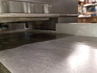
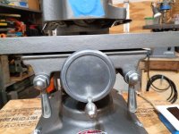
    3. Re-install the head. The table is set up to rock on curved supports cast into the planer knee. This allows you to adjust its parallelism relative to the cutterhead.
    4. The manual says to align the table to the head by laying a piece of wood on the table and turning the height handwheel until the wood locks into one of the flats of the cutterhead, rocking the table till it hits the cutterhead parallel.
    5. The problem is, you have almost no visibility while doing this with a board, so I used a stack of 123 blocks instead.
    6. I ran a board through the planer, but got 0.015" difference in thickness between each edge.
      1. Note, I used a cheap $20 set of blocks and the cutterhead itself may have had its own tolerances in flatness adding to the error.
      2. Also, since the knee casting always has a few thousands of slop in it while being raised/lowered on the ways, this error is also added in.
    7. I established which side was high, then put the 123 blocks back and loosened the table rocking bolts so that the table was still rather tight and would only rock with a lot of finger pressure.
    8. I then every so slightly forced the table to rock towards the high side of the cut, then tightened the bolts and ran another cut, and measured for the high side again. It took (3) tries in total to get the cut to only 0.003" variance across the width of the board, where I decided to stop.
The manual says that the planer originally came with two independent fences, one on either side of the head casting. My planer was missing these.
  1. With independent fences, when planning a board that maximizes the width capacity of the planer, you risk running the board into the corner of the fence beyond for short pieces.
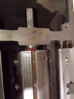
  2. I chose to make a new single-rail fence by cutting slots out of a piece of 1"x1"x1/8" aluminum angle.
  3. I slotted the angle twice, once to fit past the column casting (1/2" deep slot) and then to fit under the cutterhead and blades (left only 3/16" of angle projecting above the table)
    1. I don't plan to plane anything under 1/4" thick, so having 3/16" of fence below the blades works for me.
 

Attachments

  • IMG_20260802_165646883.jpg
    IMG_20260802_165646883.jpg
    659.7 KB · Views: 26
  • IMG_20260802_164427661.jpg
    IMG_20260802_164427661.jpg
    463.6 KB · Views: 24
  • IMG_20260802_133201334.jpg
    IMG_20260802_133201334.jpg
    651.7 KB · Views: 24
  • IMG_20260802_133147581.jpg
    IMG_20260802_133147581.jpg
    640.6 KB · Views: 26
  • IMG_20260802_133142002.jpg
    IMG_20260802_133142002.jpg
    655.3 KB · Views: 28
  • IMG_20260802_133137932.jpg
    IMG_20260802_133137932.jpg
    680.1 KB · Views: 29
  • IMG_20260802_133124510.jpg
    IMG_20260802_133124510.jpg
    670.3 KB · Views: 27
  • IMG_20260802_133107687.jpg
    IMG_20260802_133107687.jpg
    650.4 KB · Views: 25
  • IMG_20260802_133058243.jpg
    IMG_20260802_133058243.jpg
    624.6 KB · Views: 21
  • IMG_20260802_133053402.jpg
    IMG_20260802_133053402.jpg
    608.4 KB · Views: 20
To avoid these ads, REGISTER NOW!
OP
P

Placeholder17

Well-known member
Joined
Feb 25, 2024
Messages
107
Location
Maryland
More photos of the guts of the head casting and cutterhead/spindle assembly, as well as the new fence.
 

Attachments

  • IMG_20260713_065657726.jpg
    IMG_20260713_065657726.jpg
    435.2 KB · Views: 18
  • IMG_20260713_095234024.jpg
    IMG_20260713_095234024.jpg
    641.2 KB · Views: 14
  • IMG_20260713_095238914.jpg
    IMG_20260713_095238914.jpg
    503.3 KB · Views: 14
  • IMG_20260713_100402896.jpg
    IMG_20260713_100402896.jpg
    542.2 KB · Views: 15
  • IMG_20260713_100408680.jpg
    IMG_20260713_100408680.jpg
    624.3 KB · Views: 15
  • IMG_20260713_101017684.jpg
    IMG_20260713_101017684.jpg
    562.2 KB · Views: 15
  • IMG_20260713_121001192.jpg
    IMG_20260713_121001192.jpg
    604.4 KB · Views: 16
  • IMG_20260802_164355759.jpg
    IMG_20260802_164355759.jpg
    520.4 KB · Views: 15
  • IMG_20260802_165639022.jpg
    IMG_20260802_165639022.jpg
    633 KB · Views: 19
OP
P

Placeholder17

Well-known member
Joined
Feb 25, 2024
Messages
107
Location
Maryland
Those such interesting looking planers. Nice job on the resto! Pics making shavings?
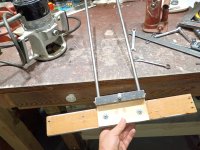
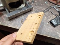
Planing down a piece of board used in a homemade router edge/circle cutting guide for a vintage industrial Black and Decker 2Hp router to get it to pass over the working surface.
 

Attachments

  • IMG_20260804_222235520.jpg
    IMG_20260804_222235520.jpg
    815.4 KB · Views: 8
  • IMG_20260804_222203008.jpg
    IMG_20260804_222203008.jpg
    516 KB · Views: 8
  • IMG_20260804_222154361.jpg
    IMG_20260804_222154361.jpg
    771 KB · Views: 8
  • IMG_20260804_221124278.jpg
    IMG_20260804_221124278.jpg
    720.5 KB · Views: 8
  • IMG_20260804_221117738.jpg
    IMG_20260804_221117738.jpg
    739.4 KB · Views: 9
  • IMG_20260804_221110607.jpg
    IMG_20260804_221110607.jpg
    673.2 KB · Views: 15
OP
P

Placeholder17

Well-known member
Joined
Feb 25, 2024
Messages
107
Location
Maryland
Additional info regarding blade/spring adjustment:

  • The original projection of the blades beyond the flats of the cutterhead is unknown. The manual does not state this. The manual says to replace blades once they are down to 9/16" wide.
  • My blades were 9/16" wide. I set them to project 1/4" past the flats using a pair of 1/8" parallels.
  • At this setting, when trying to plane wood, the front kickback hinge was able to deflect to permit the wood to pass. However, the rear hinge hit the cast iron head casting lip and the wood had to be forced through with difficulty.
  • I was able to perfectly balance the pressure from the front and back hinges as follows:
    • I shimmed the back hinge assembly below the head by placing pairs of 1/4" washers on the screws between the hinge and head.
    • However, this resulted in the bent piece of spring steel exerting too much downward pressure.
    • Bend the rear spring to be flat without any bend/curve. Leave the front kickback hinge and bent spring alone. Now the pressure on the wood is equal front and back.
  • Since the rear assembly was hitting the head with 1/4" blade projection from cutterhead, and I fixed it with a stack of washers roughly equivalent to a 1/8" shim, I presume the original blade projection is 3/8" beyond the flats.
 
Last edited:
To avoid these ads, REGISTER NOW!

RTM

Well-known member
Joined
May 13, 2019
Messages
13,412
Location
SF Bay Area
Since the rear assembly was hitting the head with 1/4" blade projection from cutterhead, and I fixed it with a stack of washers roughly equivalent to a 1/8" shim, I presume the original blade projection is 3/8".
No offense, but that sounds RIDICULOUSLY high. My planer has a much lower number. I have a vintage measuring tool for setting it on a jointer, an the throw of the device is much lower.

I put my question into google, and here is the AI answer, 0.10”. (Sorry, here to the end, wa not italicizing well)


For the vintage Sears Craftsman "Alien Head" 6-inch surface planer (Model 103.1801 or 103.23700) , the blade projection above the cutterhead body is traditionally set to roughly 0.10 inches (approx. 2.5 mm), though vintage machinery relies on precise alignment with the bed rather than an isolated absolute measurement. [1, 2, 3]


For the vintage Sears Craftsman "Alien Head" 6-inch surface planer (Model 103.1801 or 103.23700) , the blade projection above the cutterhead body is traditionally set to roughly 0.10 inches (approx. 2.5 mm), though vintage machinery relies on precise alignment with the bed rather than an isolated absolute measurement. [1, 2, 3]


Understanding the "Alien Head" Planer

  • Design: A manual-feed bench surface planer manufactured historically by Central Specialty Co. for Sears.
  • Cutterhead: Features a 6-inch cutting width with gibs and slots holding the individual knives.
  • Challenge: Because original factory blade-setting jigs or proprietary gauges are rarely found today, setting projection requires manual alignment shop techniques. [1, 2, 4, 5, 6]
Setting and Adjusting Blade Projection
  • Use a Reference Block: Rest a precision straightedge or a flat reference block gently across the planer bed/table.
  • TDC Alignment: Rotate the cutterhead manually so the blade tip reaches Top Dead Center (the absolute highest point of its arc).
  • The "Kiss" Standard: Adjust the knife bolts/gibs so that when the blade hits top dead center, it should just barely "kiss" or graze a precise straightedge placed on the table without lifting it significantly.
  • Parallel Verification: Ensure both ends of the knife project identically to prevent ridges or uneven tear-out on your 6-inch stock.
  • Lock and Test: Tighten the gib screws evenly across the assembly, and run a sacrificial piece of scrap soft pine through on a very shallow manual pass to verify smooth cutting before regular use. [5, 11]
If you need more specific restoration steps, tell me:Are you missing the gib screws or gibs?Do you need advice on safely feeding wood through this manual-feed machine?
AI responses may include mistakes.
[1] https://thepatriotwoodworker.com/forums/topic/24834-alien-invasion-1031801-planer/
[2] https://www.youtube.com/watch?v=6cs5cUZXMuA
[3] https://www.lumberjocks.com/threads/craftsman-alien-planer-103-1801.62929/
[4] https://thepatriotwoodworker.com/forums/topic/24834-alien-invasion-1031801-planer/
[5] https://www.facebook.com/groups/woodworkingforbeginner/posts/2750659045088703/
[6] https://www.woodworkingtalk.com/threads/setting-planer-blade-without-a-knife-gauge.234054/
[7] https://www.airplanesandrockets.com/woodworking/craftsman-jointer-planer-cutter-adjustment.htm
[8] https://www.garagejournal.com/forum/threads/craftsman-6-alien-head-bench-planer-disassembly-blade-table-setting-and-fence-replacement.559717/
[9] https://forum.shopsmith.com/viewtopic.php?t=31014
[10] https://www.finewoodworking.com/forum/thickness-planing-to-a-set-thickness
[11] https://www.youtube.com/watch?v=7dXZAaL5TFU
 
OP
P

Placeholder17

Well-known member
Joined
Feb 25, 2024
Messages
107
Location
Maryland
No offense, but that sounds RIDICULOUSLY high. My planer has a much lower number. I have a vintage measuring tool for setting it on a jointer, an the throw of the device is much lower.

I put my question into google, and here is the AI answer, 0.10”. (Sorry, here to the end, wa not italicizing well)


For the vintage Sears Craftsman "Alien Head" 6-inch surface planer (Model 103.1801 or 103.23700) , the blade projection above the cutterhead body is traditionally set to roughly 0.10 inches (approx. 2.5 mm), though vintage machinery relies on precise alignment with the bed rather than an isolated absolute measurement. [1, 2, 3]


For the vintage Sears Craftsman "Alien Head" 6-inch surface planer (Model 103.1801 or 103.23700) , the blade projection above the cutterhead body is traditionally set to roughly 0.10 inches (approx. 2.5 mm), though vintage machinery relies on precise alignment with the bed rather than an isolated absolute measurement. [1, 2, 3]


Understanding the "Alien Head" Planer

  • Design: A manual-feed bench surface planer manufactured historically by Central Specialty Co. for Sears.
  • Cutterhead: Features a 6-inch cutting width with gibs and slots holding the individual knives.
  • Challenge: Because original factory blade-setting jigs or proprietary gauges are rarely found today, setting projection requires manual alignment shop techniques. [1, 2, 4, 5, 6]
Setting and Adjusting Blade Projection
  • Use a Reference Block: Rest a precision straightedge or a flat reference block gently across the planer bed/table.
  • TDC Alignment: Rotate the cutterhead manually so the blade tip reaches Top Dead Center (the absolute highest point of its arc).
  • The "Kiss" Standard: Adjust the knife bolts/gibs so that when the blade hits top dead center, it should just barely "kiss" or graze a precise straightedge placed on the table without lifting it significantly.
  • Parallel Verification: Ensure both ends of the knife project identically to prevent ridges or uneven tear-out on your 6-inch stock.
  • Lock and Test: Tighten the gib screws evenly across the assembly, and run a sacrificial piece of scrap soft pine through on a very shallow manual pass to verify smooth cutting before regular use. [5, 11]
If you need more specific restoration steps, tell me:Are you missing the gib screws or gibs?Do you need advice on safely feeding wood through this manual-feed machine?
AI responses may include mistakes.
[1] https://thepatriotwoodworker.com/forums/topic/24834-alien-invasion-1031801-planer/
[2] https://www.youtube.com/watch?v=6cs5cUZXMuA
[3] https://www.lumberjocks.com/threads/craftsman-alien-planer-103-1801.62929/
[4] https://thepatriotwoodworker.com/forums/topic/24834-alien-invasion-1031801-planer/
[5] https://www.facebook.com/groups/woodworkingforbeginner/posts/2750659045088703/
[6] https://www.woodworkingtalk.com/threads/setting-planer-blade-without-a-knife-gauge.234054/
[7] https://www.airplanesandrockets.com/woodworking/craftsman-jointer-planer-cutter-adjustment.htm
[8] https://www.garagejournal.com/forum/threads/craftsman-6-alien-head-bench-planer-disassembly-blade-table-setting-and-fence-replacement.559717/
[9] https://forum.shopsmith.com/viewtopic.php?t=31014
[10] https://www.finewoodworking.com/forum/thickness-planing-to-a-set-thickness
[11] https://www.youtube.com/watch?v=7dXZAaL5TFU
This is relative to the flats of the cutterhead, not the clean circumference of the cylinder. On my Craftsman 6" jointer (NOT planer) from the 50's, which the seller said came from the estate of a friend who ran a woodshop, the blades are set at about 5/16" above the flats of the cutterhead.

I used the flats as a reference point because I had parallels on hand. I have bolded/underlined that part of my post now. I don't have a jig for measuring projection beyond the circumference.
 

RTM

Well-known member
Joined
May 13, 2019
Messages
13,412
Location
SF Bay Area
Flats jumped as tabletop to my tired brain, which is what you do in a joiner (not a planer, duh). Continuing my off tangent reply, before I dig for the answer you really need.

If you have a dial indicator, you can probably quickly make a tool if you have machining skills. I had a Delrin block made for one at work, to avoid scratching the highly polished surfaces we were measuring. Large flat stock, 2” wide, with a bunch removed at one end to create a shelf, and a keyhole to drop the indicator thru, screw across the gap to keep it fixed (pic tomorrow)

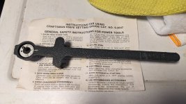
Here is the factory tool.

PXL_20240703_152624287-X3.jpg
PXL_20240703_152635058-X3.jpg
 

RTM

Well-known member
Joined
May 13, 2019
Messages
13,412
Location
SF Bay Area
Ok, now I’m sure you know already, the manual I found *****, the one pic which might have helped was ruined by poor contrast. But I did find a picture of the blade setting jig on VM, which is probably not much help either. (AI supplied the link, was amazed)


Other manuals linked here, Aug 26, 2024 post
Seems like both models used the same gage.

No one at VM talks about using said gage

At OWWM, there is this post, with various links, but only one post says 1/16” from the cutterhead. (Tue Nov 21, 2023 2:16 pm)

 
To avoid these ads, REGISTER NOW!
Top Bottom