Can a single manual transfer switch be wired to two main panels (both from same meter but they do not feed each other)? Specifically, if desired breakers cannot be consolidated into one panel and there is only going to be one 10-circuit transfer switch -- can new #12 wires be added/spliced into the existing black, red, white and ground wires coming out of transfer switch harness to extend their length so that some of them run to the second panel? Particularly, is it ok to have the neutral and ground wires from the single transfer switch be spliced so that they attach to the neutral/ground bars in both panels?

You are using an out of date browser. It may not display this or other websites correctly.
You should upgrade or use an alternative browser.
You should upgrade or use an alternative browser.
One transfer switch, two main panels
- Thread starter joelkranz
- Start date
theoldwizard1
Well-known member
Need more info.
So there is a double feed off of the meter OR is one "ahead" of the other. Pictures with the cover off help.
joelkranz said:two main panels (both from same meter but they do not feed each other)
So there is a double feed off of the meter OR is one "ahead" of the other. Pictures with the cover off help.
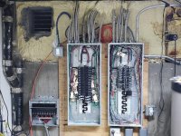
nadogail
Well-known member
Pick which circuits you want and need to have in a emergency, then move them into another panel, then connect the Gen Tran switch to it.
What he said.
wyliesdiesels
Well-known member
I second what Norcal said. You dont want the transfer switch controlling circuits in both panels.
Hell i would get rid of the gen tran, put a subpanel in, move emergency circuits over to subpanel and then do an interlock with gen inlet.
This way you only have two breakers to flip.
Hell i would get rid of the gen tran, put a subpanel in, move emergency circuits over to subpanel and then do an interlock with gen inlet.
This way you only have two breakers to flip.
Thanks, it's actually complicated to move breakers from one panel to the other (at least for me) since the feeds are stuck in the insulation and I would need several new junction boxes to extend. As it happens, I just got off the phone with Reliance about this and they say that since there is a neutral wire coming into the panel on left (closest to transfer switch) it is ok to run only red/black wires to panel at right to power a few breakers and have the neutral/ground wires from transfer switch harness only attached in left panel.
wyliesdiesels
Well-known member
We need to backup.
These look like subpanels (i see 4-wire feeder in each) NOT main panels.
Can you confirm whether there is a breaker/disconnect at the meter
These look like subpanels (i see 4-wire feeder in each) NOT main panels.
Can you confirm whether there is a breaker/disconnect at the meter
wyliesdiesels
Well-known member
Hard to say without seeing it. Post some pictures
theoldwizard1
Well-known member
I second what Norcal said. You dont want the transfer switch controlling circuits in both panels.
Hell i would get rid of that gen tran, put a subpanel in, move emergency circuits over to subpanel and then do an interlock with gen inlet.
This way you only have two breakers to flip.
Words to live by !
theoldwizard1
Well-known member
Thanks, there are two breaker boxes at the meter, one large and one small. I assume one for each panel?
Hard to say without seeing it. Post some pictures
Concur with Wylie. If you are going to be going a generator interlock it has to be at the first disconnect.


theoldwizard1
Well-known member
Here are pictures of where the service comes into garage, as helpful. Post above has picture of the panels themselves.
Okay, where is the meter and how does power get from the meter to those panels ?
wyliesdiesels
Well-known member
Those arent breakers, they are general duty safety switches. Do they have fuses in them?
Where is the meter at? Can you take a picture of the meter?
Where is the meter at? Can you take a picture of the meter?
Innovate1
Well-known member
Maybe I am missing something but it seems like you could just put a conduit (or a couple) between the panels. Then splice onto the circuits you need to move from one panel to the other, put all the circuits you want to have emergency power in one panel, and apply an interlock to that panel. The panels have lots of room in them so no need for extra junction boxes or disturbing the wires in insulation.
510ebl
Well-known member
Maybe I am missing something but it seems like you could just put a conduit (or a couple) between the panels. Then splice onto the circuits you need to move from one panel to the other, put all the circuits you want to have emergency power in one panel, and apply an interlock to that panel. The panels have lots of room in them so no need for extra junction boxes or disturbing the wires in insulation.
I don’t see a “main” breaker in either panel for the interlock. I think this is why wyliesdiesels said the whole-panel interlock won’t install on these panels.
OP: How many circuits are you trying to connect in each box? 5 and 5? 3 and 7? 9 and 1? Moving them as described above might be viable to keep the transfer switch connections in one panel only.
Question: Shouldn’t the interlock be mounted to plywood too?
Last edited:
GLTHFJ60
Well-known member
Each circuit in the transfer switch is independent, but the transfer switch panel has shared neutral and ground wires, assuming that's a reliance pro-tran 2 (looks like it is).
If both of those panels pictured share ground and neutral conductivity (whether or not they're bonded) then I don't see why you can't have some circuits from each panel on the transfer switch.
Disclaimer: not an electrician, but I do play one on TV.
If both of those panels pictured share ground and neutral conductivity (whether or not they're bonded) then I don't see why you can't have some circuits from each panel on the transfer switch.
Disclaimer: not an electrician, but I do play one on TV.
Innovate1
Well-known member
I don’t see a “main” breaker in either panel for the interlock. I think this is why wyliesdiesels said the whole-panel interlock won’t install on these panels.
OP: How many circuits are you trying to connect in each box? 5 and 5? 3 and 7? 9 and 1? Moving them as described above might be viable to keep the transfer switch connections in one panel only.
Question: Shouldn’t the interlock be mounted to plywood too?
You are right. I should have looked more closely.
Still, there is plenty of room in the panels to connect to the circuits and run them into another panel with interlock as Wyliediesel noted. I have read that splices in the panel are allowed - not sure if runs through the panel that are controlled by another panel are allowed but unless that is an issue there are quite a few things that could be done including moving circuits between panels so the generator circuits were all on one panel. That would eliminate what seems to be the major issue of two different neutral buses.
Innovate1
Well-known member
Each circuit in the transfer switch is independent, but the transfer switch panel has shared neutral and ground wires, assuming that's a reliance pro-tran 2 (looks like it is).
If both of those panels pictured share ground and neutral conductivity (whether or not they're bonded) then I don't see why you can't have some circuits from each panel on the transfer switch.
Disclaimer: not an electrician, but I do play one on TV.
The issue is that you would be bonding the two neutral bars together. It wouldn't be bonding them to ground but still is an issue with providing multiple paths for unbalanced neutral current.
AP514
Well-known member
I am doing the exact same thing as the OP.....
I have several circuits going to the Main Bonded Panel. This is where my Ground and Neutral from the Mansual Transfer Switch will go to.
I then will have several Circuits go from the MTSwitch to my Second Panel (Unbonded).
I do not see a problem with doing it.....?? THOUGHTS ??
I have several circuits going to the Main Bonded Panel. This is where my Ground and Neutral from the Mansual Transfer Switch will go to.
I then will have several Circuits go from the MTSwitch to my Second Panel (Unbonded).
I do not see a problem with doing it.....?? THOUGHTS ??
GLTHFJ60
Well-known member
The issue is that you would be bonding the two neutral bars together. It wouldn't be bonding them to ground but still is an issue with providing multiple paths for unbalanced neutral current.
If the sub-panels are both neutral bonded to the main, then adding this transfer switch that bonds the two sub-panels together is not adding or removing a connection, right?
Innovate1
Well-known member
If the sub-panels are both neutral bonded to the main, then adding this transfer switch that bonds the two sub-panels together is not adding or removing a connection, right?
Wrong! The neutral and ground are bonded at some point too but you can't just hook them together other places.
GLTHFJ60
Well-known member
Wrong! The neutral and ground are bonded at some point too but you can't just hook them together other places.
Cool. Care to explain why? Saying "multiple paths for unbalanced neutral current" doesn't do it for me, because in my mind, that current is finding the shortest path to the source (main).
Innovate1
Well-known member
For example assume the neutral wire has 0.1 ohms of resistance. Assume a 200A panel with 50 A of unbalanced current. The neutral wire would have 50A of current and the voltage drop would be 5 volts. If the other panel has balanced current it's neutral wire would have 0 amps and 0 voltage drop. If you connect the two together the voltage difference will force half the current will go through the bonding wire between panels so that 25A returns through each neutral wire. If the wire isn't big enough it could burn out the neutral wire between the two. If the original neutrals aren't the same size it could put more current through the smaller original neutral wire than it was designed to handle and could burn it out. In the OPs case the wires are likely much shorter so the resistance is less but the principle is the same.
Will it cause bad things to happen? Maybe. Depends on a lot of details of a particular situation.
Is it to code? Definitely not.
Will it cause bad things to happen? Maybe. Depends on a lot of details of a particular situation.
Is it to code? Definitely not.
wyliesdiesels
Well-known member
Cool. Care to explain why? Saying "multiple paths for unbalanced neutral current" doesn't do it for me, because in my mind, that current is finding the shortest path to the source (main).
neutral current doesnt just use the least resistant (shortest is not a correct term) path back to the source. it will use all pathways. this is why there is to be only ONE neutral bonding point on a system, so as to prevent shock potential from neutral return current.
In the OPs case, he has 2 subpanels NOT mains so need to tread carefully here.
Innovate1
Well-known member
Wyliesdiesels, it's connecting the two neutrals together not connecting neutral to ground. I probably shouldn't have used the word "bonding". So the issue isn't shock potential from current (and resultant voltage) in the ground conductor. But the neutral current would still have multiple paths. Still not a good thing.
GLTHFJ60
Well-known member
TIL. Thanks guys.