To avoid these ads, REGISTER NOW!

Question on grounding

toyotadriver

Well-known member
Joined
Dec 30, 2010
Messages
1,586
I'm in the process of finishing up a shop building and then will build the house....if I can ever sell my current house.

Anyway, the power will run from the pole to the shop building. From there it will run (4/0, 4/0, 4/0, 2/0) to the house after running through a 200 amp generator transfer switch. So, since we are running 4 cable service entrance cable instead of the more common 3 cable (more common in this area at least), I plan to bond the ground and neutral at the service entrance only. Of course, I plan to use dual ground rods set at least 8 ft apart at the service entrance.

My question is, could there be a value to installing another dual ground rod set up at the house panel? The ground and neutral will not be bonded at the house panel because it's bonded at the service entrance.

I want to make sure that there is a solid ground no matter what.

Thanks in advance.
 
To avoid these ads, REGISTER NOW!

Aceman

Well-known member
Joined
Jan 28, 2007
Messages
2,513
Location
Eastern Oregon
You need to have a grounding electrode system installed at ALL seperate structures when you run a feeder to them. Whether you use a ufer, water pipe, or rods, it doesn't matter. If you have a metal water pipe with 10' or more of metal in contact with the soil you must hit it with a ground wire as well as install or hit another electrode to supplement it. Most cases we hit the water pipe on existing services and drive 2 rods. Make sense?
 

PRH44

Well-known member
Joined
Dec 25, 2009
Messages
563
Location
Indiana
Is the house receiving service from the shop only and no other sevice?
Are you installing a fused disconnect after the meter enclosure?
Will this disconnect serve as your only main to both shop and house?
If the shop is the one and only service/main disconnect The following instructions shall apply.
Install the bonding jumper in this main disconnect. This is usually in the form of a green screw supplied with the disconnect. It will normally be attched to a tag with instructions printed on it. This wiill bond the enclosure to the neutral.
On this neutral bus there will be provisions to terminate a #6 ground wire from the ground rod. Bond both ground rods togather. Ground and metal piping, metal ductwork. Grounding rebar in the concrete can also be done
Terminate the ground and neutral on the neutral bus in the disconnect. This will be the only location you will do this
Install the conductors and terminate as follows on the load side of your main disconnect.

4/0 Phase A color black
4/0 Phase B color red
4/0 Neutral color white (grounded conductor)
2/0 Ground color green (grounding conuctor)
The neutral and ground on the same bus as stated above.

Your transfer switch should be provided with what is called a solid neutral. This will a bus on and insulator with provisions to terminate the incoming and outgoing neutral and the neutral from the generator. Make sure the generator does not have a bonding jumper attaching the neutral to ground in the Genset. Run the bond wire from the generator ground with the other conductors and bond to the ground in the transfer switch. This ties the generator frame to the ground in the transfer switch.

If your transfer switch breaks/switches the neutral it must be treated as a seperatly derived system and the grounding scheme will change. Let me know


The grounding conductor 2/0 will attach directly to the transfer switch cabinet along with the ground from the generator and outgoing ground to the house.There should be a supplied lugs to do this, if not you can install lugs by drilling and cleaning the paint from the surface behind the lug and bolt tight. DO NOY USE SHEET METAL SCREWS

At the house you will terminate the 2/0 ground on the ground bus only. The 4/0 neutral conductor will terminate on the insulated neutral bus. Be sure there are no bonding jumpers or screws connecting the neutral to the ground or cabinet.
All ground wires from the house branch circuits will terminate to the ground bus only. All the neutrals from the house branch circuits will attach to the neutral bus only. This is very important.

You will then drive a supplemetal ground rod(s) at the house and bond them to gather and attach them to the ground bus only. Bond all metal piping, ductwork, etc in the house.

Most engineers prefer a triad configuration using three rods. two should be sufficient. I know this is more tha you asked but generators can be very dangerous if not grounded correctly
 
OP
T

toyotadriver

Well-known member
Joined
Dec 30, 2010
Messages
1,586
The generator has a floating ground.

The transfer switch does not switch the neutral. Hot only.

The transfer switch neutral and ground are not connected in the transfer switch. The neutral is insulated from the ground in the transfer switch. It is only bonded in the meter box.

The meter box contains a 200 amp breaker for the entire house/shop service.
 

PRH44

Well-known member
Joined
Dec 25, 2009
Messages
563
Location
Indiana
The above instructions fit your install. Make sure you use anti-oxide on your AL connections Completely cover the stripped area of conductor like a good thick paint job. A brush works great for this. Torque valus are important to follow as aluminum suffers creap. The compact stranding in the newer Aluminum cable is a huge improvement in this area. Hope you get your house sold soon so you can get started good luck.
 
OP
T

toyotadriver

Well-known member
Joined
Dec 30, 2010
Messages
1,586
Thanks for the info!

I have installed the transfer switch and the meter box. I have used plenty of the anti oxide paste on the connections and re-torqued the connections. When I'm done with the house connections, I'll probably have used up an entire bottle of it!!

I'll be installing more grounding rods at the house...when I finally start it.

Thanks again for the help.
 
To avoid these ads, REGISTER NOW!

Falcon67

Well-known member
Joined
Jun 11, 2009
Messages
18,371
Location
Merkel, TX
>I'll be installing more grounding rods at the house...when I finally start it.
Bury 20+ feet of #4 copper in the foundation - it's a much better ground than any driven rod.
 
OP
T

toyotadriver

Well-known member
Joined
Dec 30, 2010
Messages
1,586
>I'll be installing more grounding rods at the house...when I finally start it.
Bury 20+ feet of #4 copper in the foundation - it's a much better ground than any driven rod.


Just in the foundation? How does it get to soil? Does it have to be attached to the rebar?

I guess I didn't think that concrete was that conductive.
 

Aceman

Well-known member
Joined
Jan 28, 2007
Messages
2,513
Location
Eastern Oregon
What's typical here in Oregon, we have the concrete contracter/GC stub a piece of rebar up in the wall under the panel location. Then when the building inspector shows up to inspect the footing(before it's poured!) he puts a green tag on this piece of rebar approving it's use as a ufer ground.

Then all you do is throw a ufer clamp on the bar and run some #4 up into the panel. Be sure this connection remains accessible after sheetrock/sheeting goes up. We usually screw a 2 gang mud ring to the studs and then put a blank cover over it on trim out.

If you're pouring a footing with no rebar in it, then you can just lay 20' of #4 bare copper across some dobies and make your own ufer. But, if you already have rebar in the footing, use that.
 

PRH44

Well-known member
Joined
Dec 25, 2009
Messages
563
Location
Indiana
Aceman raises a good point. If the footer has not been installed you have chance to install what is known as a concrete incased electrode.

In most industrial and some commercial the grounding is intense. installing a 4/0 ground ring around the entire structure driving 3/4" X 10 grounds every 100 feet or more. Then tie to rebar in the footings in multiple locations normally using a Cadweld. We stub up copper conductor at several steel columns and weld to them Stubs to all electrical and telecom rooms, generators and like equipmnet. Run lightning protection down leads to the roof in several locations some are 30 to 40 stories tall. Then apply a lightning protection grid of cable and air terminanls (lightning rods) also grounding all ductwork and metal penetrations through the roof including drains.
Its expensive and a lot of work but very important.

Just too spark your curious side
 

Falcon67

Well-known member
Joined
Jun 11, 2009
Messages
18,371
Location
Merkel, TX
Just in the foundation? How does it get to soil? Does it have to be attached to the rebar?

I guess I didn't think that concrete was that conductive.

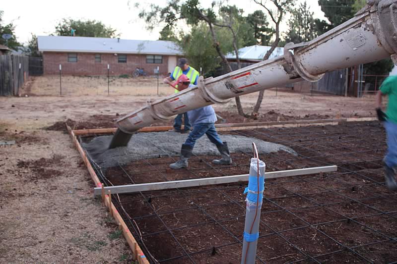
Concrete is very conductive, which is why that is acceptable. I used copper so I had a clean unbroken connection from the slab to the grounding bus in the panel. I just loosly hung it from the rebar layed for the foundation.

You can see it in this picture:
Foundation11.jpg
 
Last edited:
OP
T

toyotadriver

Well-known member
Joined
Dec 30, 2010
Messages
1,586
I did some reading about this. Only issue I found was that a lightning strike could cause cracks in the concrete when energized and thus heating up. I'm guessing that's a very low risk though. I'm kind of leaning toward using the UFER type of ground. The house (when we build it) will have a fill basement so it would be pretty easy to install a grounding wire all the way from the ground in the basement all the way to the house panel.

Thanks for the info and the pics!!
 
To avoid these ads, REGISTER NOW!
Top Bottom