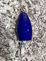
About six years ago we had our kitchen remodeled, and as part of the changes my wife got three blue pendant lights that she really likes. About nine months ago one of them died and I rebuilt it. And about a week ago the second one died and I just got it rebuilt and working again, and this time with pictures. Maybe someone will need to do similarly so that's why I've documented what I did.
My original thought was to just replace them when they failed, as they have integrated lights and not bulbs. Unfortunately they are expensive, not available any more, and my wife really loves them so...
Here are two of the lights with the third one removed:
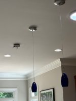
The way the lamps work is that there is a power supply in the ceiling part of the fixture that drives the LEDs in the lamp below. To make this fix I need to replace both parts. The next pic shows the major components of the lamps. You can see the integrated LEDs on the right part of the picture.
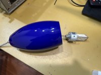
Here is a close up of the emitter.
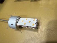
And this is the disassembled emitter. For mine I had to unsolder the wires which was no big deal. Note that the emitter has a solid aluminum chunk through the center that I expect is supposed to act as a heat sink. Since the lamps hang upside down I expect that the LEDs get rather hot. And the heat sink doesn't work that well given that the LEDs seem to last only 5-6 years... BTW the printed circuit boards are glued to the aluminum so good luck replacing a board assuming that you could find one.
I wasn't will to accept a solution like this in my fix, as if the LED dies I want to be able to unscrew the dead one and put in a new one.

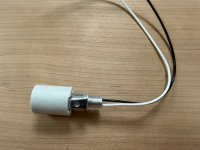
The key to the fix is the bulb socket below. I got these off of Amazon, and I got ceramic in the theory that it might transfer heat a bit better away from the LED than plastic. In any case it has a metal part to the right that is threaded, and then you can screw in a standard threaded tube to support it.
This shows a full length tube, but to make it work in my light I needed to cut the tube in half with a hacksaw.
It too k me longer than it should have the first time to figure out how to make this all work. The solution is to drill out the mounting plate such that the threaded tube will go through it. Fortunately the plate has three screw holes already, so it was just a case of mounting the plate to a piece of scrap wood and drilling.

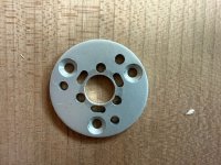
Here is the drilled out plate in detail. I eyeballed the center so you can see I am a tiny bit off of center, which won't matter at all in the final assembly. Apologies in advance to any OCD machinists who see this...
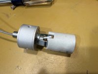
The wires from the socket need to connect up to the cable as the old part did, so they have to be shortened up a lot, soldered to the original wires, and heat shrinked. Here is the final assembly with the new lamp base.
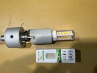
And this is what it looks like with a bulb in it, as well as the bulb box. It's not much longer than the original assembly so there are no issues with the bulb hanging too low later.
Well I've reached my 10 picture limit so I'll stop here and add another thread.
My original thought was to just replace them when they failed, as they have integrated lights and not bulbs. Unfortunately they are expensive, not available any more, and my wife really loves them so...
Here are two of the lights with the third one removed:
The way the lamps work is that there is a power supply in the ceiling part of the fixture that drives the LEDs in the lamp below. To make this fix I need to replace both parts. The next pic shows the major components of the lamps. You can see the integrated LEDs on the right part of the picture.
Here is a close up of the emitter.
And this is the disassembled emitter. For mine I had to unsolder the wires which was no big deal. Note that the emitter has a solid aluminum chunk through the center that I expect is supposed to act as a heat sink. Since the lamps hang upside down I expect that the LEDs get rather hot. And the heat sink doesn't work that well given that the LEDs seem to last only 5-6 years... BTW the printed circuit boards are glued to the aluminum so good luck replacing a board assuming that you could find one.
I wasn't will to accept a solution like this in my fix, as if the LED dies I want to be able to unscrew the dead one and put in a new one.
The key to the fix is the bulb socket below. I got these off of Amazon, and I got ceramic in the theory that it might transfer heat a bit better away from the LED than plastic. In any case it has a metal part to the right that is threaded, and then you can screw in a standard threaded tube to support it.
This shows a full length tube, but to make it work in my light I needed to cut the tube in half with a hacksaw.
It too k me longer than it should have the first time to figure out how to make this all work. The solution is to drill out the mounting plate such that the threaded tube will go through it. Fortunately the plate has three screw holes already, so it was just a case of mounting the plate to a piece of scrap wood and drilling.
Here is the drilled out plate in detail. I eyeballed the center so you can see I am a tiny bit off of center, which won't matter at all in the final assembly. Apologies in advance to any OCD machinists who see this...
The wires from the socket need to connect up to the cable as the old part did, so they have to be shortened up a lot, soldered to the original wires, and heat shrinked. Here is the final assembly with the new lamp base.
And this is what it looks like with a bulb in it, as well as the bulb box. It's not much longer than the original assembly so there are no issues with the bulb hanging too low later.
Well I've reached my 10 picture limit so I'll stop here and add another thread.